
Related Manuals for Faulhaber Series MCBL 3002/03/06 RS/CF /CO


Summary of Contents for Faulhaber Series MCBL 3002/03/06 RS/CF /CO
- Page 1 Motion Controller Series MCBL 3002/ 03 / 06 RS / CF / CO Series MCDC 3002 / 03 / 06 RS / CF / CO Series MCLM 3002 / 03 / 06 RS / CF / CO Technical Manual WE CREATE MOTION...
- Page 2 Dr. Fritz Faulhaber GmbH & Co. KG. This technical manual has been prepared with care. Dr. Fritz Faulhaber GmbH & Co. KG cannot accept any liability for any errors in this technical manual or for the consequences of such errors.
- Page 3 (only RS232) Motion Manager instruction manual Operation of the "FAULHABER Motion Manager" PC software for configuration and commissioning Product data sheets Technical limit and operating data NOTE The documentation is available on request or on the FAULHABER internet site (www.faulhaber.com)
-
Page 4: Table Of Contents
Table of Contents 1 Important Information Symbols used in this technical manual Safety instructions Ambient conditions Servicing / maintenance Troubleshooting 2 Description Product information General product description 3 Installation Assembly instructions EMC compatible installation Connections 3.3.1 Supply end connection (MCxx 3002 / 3003 / 3006) 3.3.2 Motor end connection MCDC 3002 3.3.3 Motor end connection MCBL / MCLM 3002 3.3.4 Motor end connection MCDC 3003 / 3006... -
Page 5: Important Information
The MCBL is an external Motion Controller for brushless DC servomotors with analog Hall sensors, which can be operated without additional encoders. MCDC 3002 / 03 / 06 The MCDC is an external Motion Controller that is designed for the entire range of FAULHABER DC micro motors. MCLM 3002 / 03 / 06 The MCLM is an external Motion Controller for linear DC servomotors with analog Hall sensors, which can be operated without additional encoders. -
Page 6: Safety Instructions
The Motion Controller's parametrisation can be individually adjusted to the respective application using a PC. The "FAULHABER Motion Manager" PC software for Microsoft Windows is available for commissioning and configuration of the Motion Controllers and can be downloaded free of charge from the FAULHABER homepage www.faulhaber.com. -
Page 7: Ambient Conditions
1.5 Troubleshooting Due to their design, if the parameters given in this technical manual are complied with the drives are trouble-free. Should a malfunction occur in spite of this please contact the manufacturer. Switchboard: +49(0)7031/638-0 E-Mail: info@faulhaber.de Internet: www.faulhaber.com... -
Page 8: Description
2.1 Product information … … … … … RS 232, serial interface CAN interface FAULHABER CAN interface CiA AES: Only for brushless DC motors with absolute encoders Housing with screw-type terminal strip Housing with LIF connector (motor) Board version with male connectors Max. -
Page 9: General Product Description
2 Description 2.2 General product description The FAULHABER Motion Controllers are based on a high performance digital signal processor (DSP), which enables a high control quality, precise positionability and very low speeds. They are configured for different drive tasks; which can be configured via the respective communica- tion interface. - Page 10 2 Description 2.2 General product description „ MCxx 3002 P RS / CF / CO Motion Controller without housing (board version) with pin headers on the supply and motor end. 1 Pin header, motor end 2 Pin header, supply end „...
- Page 11 Separate power supply for the motor and control electronics is possible as an ex-factory option (im- portant for safety-relevant applications). In this case the 3rd input is not required. Special preconfiguration of modes and parameters is possible on request. NOTE The Motion Manager software can be downloaded free of charge from www.faulhaber.com/MotionManager.
-
Page 12: Installation
3 Installation 3.1 Assembly instructions CAUTION! Damage due to incorrect assembly! Improper assembly or assembly with unsuitable fixing materials can cause damage to the Motion Controller. f Observe the following assembly instructions. Specialised staff Only trained specialised staff and instructed persons with knowledge in the field of automation tech- nology and standards and regulations such as the EMC Directive, Low Voltage Directive, Machinery Directive, VDE regulations (such as DIN VDE 0100, DIN VDE 0113/EN 0204, DIN VDE 0160/EN 50178), Accident Prevention Regulations may install and commission the units. - Page 13 3 Installation 3.1 Assembly instructions Surface Motion Controllers may be screwed onto flat, hard surfaces only. The surface must be suitable for supporting the assembly sleeves against the screwing forces. Screwing onto a soft or uneven surface can cause the assembly sleeves to be pressed out. Right Wrong The Motion Controller is mounted on a flat,...
-
Page 14: Emc Compatible Installation
3 Installation 3.2 EMC compatible installation CAUTION! Length of the connection leads! The maximum length of the connection leads is limited. f All supply end connection leads, with the exception of the power supply, may not exceed a length of 3 m. The maximum allowable length of the motor connection cable depends on the encoder type used. - Page 15 3 Installation 3.2 EMC compatible installation Protective measures MCxx 3003 / 3006 Motion Controller Use environment Interference type Action MCDC 3006 S Industrial environment Emission EMC filter MCBL 3006 S Industrial environment Emission EMC filter MCBL 3006 S Industrial environment Immunity EMC suppressor circuit This table shows which additional EMC measures can be implemented to optimise the behaviour of the equipment in the intended environment with regard to emission and immunity.
-
Page 16: Connections
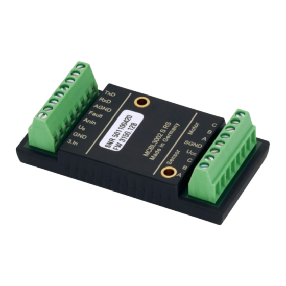
3 Installation 3.3 Connections Depending on their type, Motion Controllers are equipped with either screw-type terminal strips, flexboard plug-in connectors or pin headers as connection options. CAUTION! ESD protection / electronic damage! Electrostatic discharges at the connections of the Motion Control systems can cause irreparable dam- age to the electronics. -
Page 17: Motor End Connection Mcdc 3003 / 3006
3 Installation 3.3 Connections 3.3.4 Motor end connection MCDC 3003 / 3006 Designation Meaning 5. In 5th input 4. In 4th input Ch A Encoder channel A Ch B Encoder channel B Supply voltage for external loads SGND Signal ground connection Mot + Supply voltage, motor + Mot –... -
Page 18: Motor End Connection Examples
3 Installation 3.3 Connections 3.3.6 Motor end connection examples DC motor with encoder (at MCDC 3002*) BL / LM motor with Hall sensors Phase C 5th In Motor C Motor – Phase B Mot – DC motor Motor B BL motor Motor + Phase A Mot +... -
Page 19: Shielding The Motor Wiring
3 Installation 3.3 Connections 3.3.7 Shielding the motor wiring The encoder and signal lines are susceptible to interference, which makes it impossible to specify a maximum cable length. Shielded wires must always be used for cable lengths > 300 mm. In general it is necessary to ensure that the cables between the Motion Controller and the motor are kept as short as possible, since drive system properties such as smooth and concentric running dete- riorate as the length of the cables increases. -
Page 20: Power Supply
3 Installation 3.3 Connections 3.3.8 Power supply Supply connection Motor Int. Supply CAUTION! Power supply connections (U , GND) Malfunctions can occur if an inadequately dimensioned power pack is used. If the supply leads are incorrectly connected (polarity reversal) the internal fuse trips. This must be replaced in the factory (not possible with encapsulated versions)! f The power pack must be adequately dimensioned for the connected motor. -
Page 21: Analog Input
3 Installation 3.3 Connections 3.3.9 Analog input Internal protective circuit, analog input AGND – AnIn The analog input is implemented as a differential input. The analog GND should be connected to the power supply GND. This prevents the voltage drop in the supply cable from affecting the target velocity value. -
Page 22: Error Output
3 Installation 3.3 Connections 3.3.11 Error output CAUTION! Electronic damage! The fault output is configured as an output in the factory. Before connecting as an input, the fault pin must have been configured accordingly. The configuration must be saved (see communication and function manual / commissioning chapter). -
Page 23: Interfaces
3 Installation 3.3 Connections 3.3.12 Interfaces RS232 The RS232 wiring is established via the connections RxD, TxD and the supply GND; alternatively, the installed D-sub connector can be used (not available for all variants). The installed RS232 interface allows direct connection with a higher level control. Pin header / Terminal strip D-Sub connector Designation... -
Page 24: Connection Examples
3 Installation 3.4 Connection examples 3.4.1 Command source via potentiometer Bipolar analog command source via potentiometer Motion Controller 4,7k AnIn nsoll AGND – 20 V 4,7k Interface 3.4.2 Homing and limit switches Connection of homing and limit switches Motion Controller AnIn Fault AGND... -
Page 25: External Incremental Encoder
3 Installation 3.4 Connection examples 3.4.3 External incremental encoder Connection of an external encoder 2,7k AnIn 4 edges Encoder Encoder AGND Inter- face... -
Page 26: Communication Port
3 Installation 3.5 Communication port 3.5.1 RS232 port The drives can be directly connected to a PC or a higher level control using transposed transmission and reception cables. This corresponds to implementation with a null modem cable. Wiring between PC / control and a drive Node 1 PC or higher level control... -
Page 27: Can Port
3 Installation 3.5 Communication port 3.5.2 CAN port Node 1 Node n CAN_H CAN Bus Line CAN_L CAN is a bus system, to which all nodes are connected in parallel. A terminal resistance of 120 must be connected to each end of the bus line. In addition to the two signal lines CAN_H and CAN_L, the nodes must also be connected to each other by a common GND line. -
Page 28: Baud Rate And Node Number / Node Id
3 Installation 3.6 Baud rate and node number / node ID NOTE The baud rate and node number necessary for the communication link are set via the Motion Man- ager or as a direct command input. Please read the relevant function and communication manual and the Motion Manager's instruction manual. -
Page 29: Operation
4 Operation 4.1 Device start up To start up a drive, please read in the communication and function manual. Before starting up a drive the following points must be checked: „ The Motion Controller has been installed according to the specifications. „... -
Page 30: Ec Product Safety Directives
Therefore, the Machinery Directive does not apply to our products. The products described here are not “part machines” or “incomplete machines”. Therefore, Faulhaber does not provide a standard Declaration of Incorporation. Low-Voltage Directive (2006/95/EC): It applies to all electrical equipment with a nominal voltage from 75 to 1 500 V DC, or from 50 to 1 000 V AC. -
Page 31: Warranty
6 Warranty Extract from our warranty conditions Dr. Fritz Faulhaber GmbH & Co. KG products are produced to state of the art production methods and are subject to strict quality control. Should, contrary to all expectations, defects occur, we undertake to find a remedy within the war- ranty period. - Page 32 DR. FRITZ FAULHABER GMBH & CO. KG Antriebssysteme Daimlerstraße 23 / 25 71101 Schönaich · Germany Tel. +49(0)7031/638-0 Fax +49(0)7031/638-100 MA05038 English, 3rd edition, 03.2013 info@faulhaber.de © DR. FRITZ FAULHABER GMBH & CO. KG Subject to change without notice www.faulhaber.com...
Need help?
Do you have a question about the Series MCBL 3002/03/06 RS/CF /CO and is the answer not in the manual?
Questions and answers