Advertisement
SERIES 05-50
Connectivity Module - ConnectedControls
Interfacing with Ignition Controls
FEATURES
•
Works with Fenwal ConnectedControls mobile and
desktop applications
•
Can be configured for a company cloud network
•
Uses 2.4 GHz Wi-Fi and Bluetooth
•
Includes UART communication interface with gas ignition
control
•
Reports all states of control to the cloud
•
Provides remote reset of gas ignition control
•
Includes three proving switch inputs for appliance
features
•
Includes 4 status LEDs
•
Available Internal or External Antenna option
•
Accepts AC or DC low voltage power
APPLICATIONS
•
Radiant Heaters
•
Unit Heaters
•
Various Other Applications
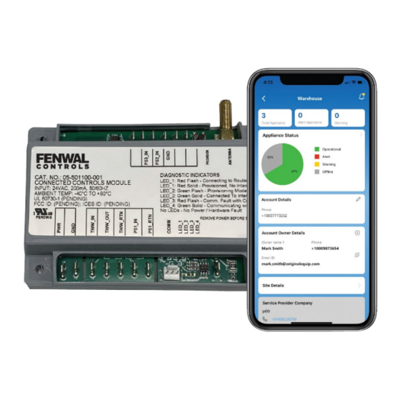
DESCRIPTION
The 05-50 connectivity module is designed to connect to a
compatible Fenwal gas ignition control, giving the appliance IoT
capability. The module communicates all state changes in the
gas ignition control to the cloud, which is made available to end
users via a mobile or desktop application. Alert conditions, such
as a lockout, are immediately pushed to the end user
applications. Data sent to the cloud can be used to trend
performance, and detect and troubleshoot issues.
The connectivity module has three additional proving switch
connections to allow monitoring additional inputs such as
inducer fans, gas pressure switches, and high limit sensors.
The Fenwal ConnectedControls software allows customers to
manage their accounts, specific sites, individual users, and
service providers. The software provides status of controls,
operational logs, and service notes. In addition, the software
provides troubleshooting tips and technical support links.
Agency Certifications
UL 60730-1
CAN/CSA E60730-1
RoHS Compliant
FCC ID:
External Antena:
2AC7Z-ESPWROOM32UE
FCC ID:
Internal Antena:
2AC7Z-ESPWROOM32E
Note:
OEM is responsible for considerations of remote reset
capability for end-use application.
®
communications
IC ID:
21098-ESPWROOMUE
IC ID:
21098-ESPWROOM32E
1
SPECIFICATIONS
Input Power
Operating Temperature
Storage Temperature
UART Communication
Thermostat & Proving Switch 1 12/24VDC, 24/120VAC
Proving Switch 2 & 3
Enclosure
Size (LxWxH)
with Enclosure
Moisture Resistance
RECOMMENDED ACCESSORIES
SMA Cable Requirements:
•
Connector: SMA Male 50 ohm to SMA Female 50 ohm
Antenna Requirements:
•
50 ohm input impedance, 2.4 GHz - 2.5 GHz, Gain 2.0 dBi
•
Example: PulseLarsen Antenna W1010
•
Antenna must be installed to provide a separation
distance of not less than 20cm from all persons and must
not be collocated or operating in conjunction with any
other antenna or transmitter.
Note:
Internal and External antenna options provide varying
Wi-Fi signal strength and range. External antenna
orientation can also impact the signal strength.
Manufactures should consider that here are trade-offs
between the two options and choose what best fits
their needs.
F-05-50
January 2023
18-30VAC, 9VA, 50/60Hz
20-28VDC, 9VA
10-14VDC, 9VA
-40°F to + 176°F
(-40°C to +80°C)
-40°F to + 185°F
(-40°C to +85°C)
5V TTL
3.3V RS485 (Option)
12 VDC, 24VAC/DC
®
Gray Cover
Noryl
4.9 x 3.5 x 1.3 inches
(12.5 x 8.9 x 3.4 cm)
95% RH non-condensing
Advertisement
Table of Contents

Related Manuals for Fenwal Controls 05-50 Series


Summary of Contents for Fenwal Controls 05-50 Series
- Page 1 SERIES 05-50 Connectivity Module - ConnectedControls Interfacing with Ignition Controls F-05-50 January 2023 FEATURES • Works with Fenwal ConnectedControls mobile and desktop applications • Can be configured for a company cloud network ® • Uses 2.4 GHz Wi-Fi and Bluetooth communications •...
-
Page 2: Operation
Operation outside specifications could result in alert conditions. Upon receiving this command, the TH relay is failure of the Fenwal Controls product and other WARNING momentarily opened and then re-closed to cycle the TH signal equipment with injury to people and property. -
Page 3: Terminal Designations
TERMINAL DESIGNATIONS Notes: Name Description Terminal Type • If the Thermostat (TH/W_IN) is 24VAC/DC, (TH/W_RT) PWR/R PWR IN 1/4” Male Q.C. should be GND. If Thermostat (TH/W_IN) is 120VAC, (TH/ W_RT) should be L2. PWR GND 1/4” Male Q.C. • If Proving Switch 1(PS1_IN) is 24VAC/DC, (PS1_RTN) should TH/W_IN TH In... -
Page 4: Led Designations
Figure 2. Wired to 120VAC Gas Control LED DESIGNATIONS Troubleshooting Guide Condition/Mode Symptom Recommended Actions LED 1 Flashing Red Connecting to Local Router 1.Dead A. Miswired (No LED’s after power up.) B. Fuse/circuit breaker fault LED 1 Solid Red Provisioned, No Internet C. - Page 5 ECCN: 5A991.g All trademarks are property of their respective owners. This document contains technical data subject to the EAR. Fenwal Controls, Kidde-Fenwal Inc. This literature is provided for informational purposes only. 400 Main Street KIDDE-FENWAL, INC. assumes no responsibility for the prod- Ashland, MA 01721 uct’s suitability for a particular application.
Need help?
Do you have a question about the 05-50 Series and is the answer not in the manual?
Questions and answers