Advertisement
Quick Links
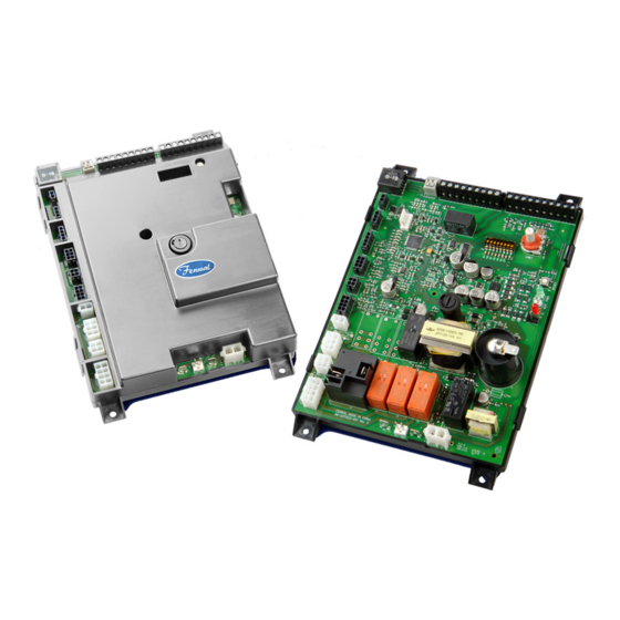
Series 35-9X Modulating
Platform Ignition Module (PIM
OPERATION AND INSTALLATION INSTRUCTIONS
DESCRIPTION
The Fenwal Controls Platform Ignition Module (PIM
the functions of Automatic Ignition Control with temperature
regulating and control functions. The PIM is designed for a range
of hydronic boilers including both staged systems and
modulating types. The PIM can be configured as a direct spark
ignition (DSI), intermittent pilot (IP) or Hot Surface Ignition
(HSI) to provide safe lighting and supervision of the burners in
an appliance. The PIM is also designed to connect to and receive
commands from the tekmar
to a Host Controller, the PIM offers expanded control
functionality including Domestic Hot Water, outdoor reset,
diagnostic messages, and other system capabilities.
APPLICATIONS
The PIM and Host Controller system is suited to a wide variety
of gas-fired hydronic heating systems including:
•
High-efficiency Modulating Condensing Boilers
•
Fan-assisted single and multi-staged Boilers
•
Multiple Boiler Installations using intelligent sequencing
•
Intermittent Pilot based Hydronic appliances
•
Water Heaters
•
Pool and Spa Heaters
AGENCY APPROVALS
CSA Design certified to ANSI Z21.20,
CAN/CSA C22.2 No. 199-M99 and ANSI
Z21.20-2014 CAN/CSA C22.2 No.
60730-2-5-14
CE Approved to EN 298-2012
1.The tekmar BTCII Boiler Controller is fully compatible with
the Fenwal PIM and provides complete hydronic boiler
operation. For more information, contact tekmar controls at
(250) 545-7749.
2. EMC Emission testing to be verified after incorporation into
end use appliance.
®
) integrates
®1
Host Controller. When connected
2
®
)
SPECIFICATIONS
Installing or operating the product inconsistent
with these instructions or specifications could
WARNING
cause serious property damage, injury or death.
Specification
Input Power
Input Current Drain
Gas Valve Relays
Combustion Blower
Hot Surface Igniter
Pump Relays
Alarm Relay
Operating Temperature
Storage Temperature
Sensor Temperature Range
Flame Sensitivity
Flame Failure Response or
Reignition Time
Flame Detector Self-check Rate Once per second minimum
Flame Failure Lockout Time
Types of Gas
Spark Rate
Size (LxWxH)
Ingress Protection
Moisture Resistance
Tries for Ignition
Trial for Ignition Period
Pre-purge Timings
Inter-purge Timings
1 of 12
F-35-2000
October 2018
Value
Control: 18-30 VAC 50/60 Hz
(Class 2 Transformer)
400 mA @ 24 VAC with gas and
blower relays energized (Control
only)
5.0A max (continuous)
5.0 A max for standard (J2)
connection
15.0 A max for heavy-duty (K5
relay) terminals
5.0 A max, 120/240 VAC
5.0 A max (continuous)
2.0 A, 30 VDC or 30 VAC max
-40°F to + 165°F (-40°C to +74°C)
-40°F to + 185°F (-40°C to +85°C)
-22°F to + 260°F (-30°C to
+126°C)
0.7 μA minimum
0.8 seconds maximum
Varies by model
Natural, LP, or manufactured
Remote sense (50/60 Hz)
Local sense (25/30 Hz)
8.50 x 6.50 x 2.50 inches
(21.59 x 16.51 x 6.35 cm)
Not rated, protection provided by
appliance in which it is installed.
Conformal coated to operate non-
condensing to 95% R.H.
One or three try versions available
1 to 30 seconds, up to 300 seconds
(IP)
1 to 255 seconds
1 to 255 seconds
Advertisement

Related Manuals for Fenwal Controls 35-9 Series


Summary of Contents for Fenwal Controls 35-9 Series
- Page 1 October 2018 OPERATION AND INSTALLATION INSTRUCTIONS DESCRIPTION SPECIFICATIONS ® The Fenwal Controls Platform Ignition Module (PIM ) integrates Installing or operating the product inconsistent the functions of Automatic Ignition Control with temperature with these instructions or specifications could regulating and control functions. The PIM is designed for a range WARNING cause serious property damage, injury or death.
- Page 2 FEATURES SENSORS The PIM provides the following features: The PIM provides standard support for 10K ohm @ 77°F NTC curve J Thermistor probes (β=3892). Special OEM models may • Integrated UL353 High Limit using Thermistor Sensor support other sensor types as outlined in the specific appliance •...
- Page 3 Configuration (DIP Switch Settings) Standby/Call for Heat The PIM includes an 8-position DIP switch, located near the field The PIM continuously monitors the flame status to wiring terminals. Use this DIP switch to set field configurable verify no flame is present during Standby. If an items when commissioning.
- Page 4 Ignition (DSI Models) The gas valve relay contacts are verified open (except isolated valve models). The PIM re-initializes the ignition counter to the The Combustion Blower is set to the Ignition light-off configured number of trials. speed (if modulating). The High Limit sensor is confirmed to read below the The Pilot gas valve output is enabled for the trial for High Limit Set Point.
- Page 5 Sensor Inputs The control attempts two additional ignition trials before going into lockout and the gas valve relay(s) are The PIM requires an outlet thermistor sensor for burner control de-energized immediately. and a high-limit thermistor sensor for the integrated UL353 high- The LED indicates the fault code for ignition lockout.
-
Page 6: Mounting And Wiring
MOUNTING AND WIRING HIGH VOLTAGE AND REMOTE SENSE CABLE REQUIREMENTS The PIM enclosure is designed to facilitate mounting within a control box by the appliance OEM. The HV Ignition Cable must meet a voltage rating of 25 KV and an insulation rating of 200 °C. Recommend length of 3ft (.9m) The PIM is not position sensitive and can be mounted vertically or less. -
Page 7: Wiring Diagrams
WIRING DIAGRAMS DSI Wiring Diagram Host Controller FT-B us B Slave FT-B us A Operator Set Point Boiler V in Identity Card Lim it For field settings, see note High Limit Sensor Reset Outlet Sensor Air Flow Safety #2 Safety #1 Remote Inlet Sensor Vent Sensor... - Page 8 HSI Wiring Diagram Host Controller FT-B us B Slave FT-B us A Operator Set Point Boiler V in Identity Card Lim it For field settings, see note High Limit Sensor Reset Outlet Sensor Air Flow Safety #2 Safety #1 Remote Inlet Sensor Vent Sensor 4 to 20 MA...
-
Page 9: Wiring Tables
WIRING TABLES OEM Factory Low-Voltage Wiring Connections (30 VAC Max) Connector Function Type and Rating Ft-bus B (PIM to PIM) Molex Micro-Fit, 20-30AWG, 2.0A Ft-bus A (PIM to PIM) Molex Micro-Fit, 20-30AWG, 2.0A ID Card Power (3.3Vdc) Molex Micro-Fit, 20-30AWG, 2.0A ID Card Signal Molex Micro-Fit, 20-30AWG, 2.0A ID Card Ground... - Page 10 OEM Factory Line-Voltage Wiring Connections Connector Function Type and Rating Valve common (isolated contact) Molex Mini-Fit Jr. 120/240VAC, 8A 2nd stage Valve Molex Mini-Fit Jr. 120/240VAC, 5A Gas Valve Return Molex Mini-Fit Jr. 120/240VAC, 5A Molex Mini-Fit Jr. 120/240VAC, 5A Stage Valve Return Gas Valve (MV/PV) Molex Mini-Fit Jr.
- Page 11 Low-Voltage Field Wiring Connections (30 VAC Max) Connector Function Type and Rating DHW sensor (to Host Controller) RJ45 System sensor (to Host Controller) RJ45 Outdoor sensor (to Host Controller) RJ45 Host Controller RJ45 Host Controller RJ45 Host Controller RJ45 24VAC Common RJ45 24VAC Power (to Host Controller) RJ45...
- Page 12 If you need more information on this product, or if you have a particular problem or question, contact KIDDE-FENWAL, INC., Ashland, MA 01721 USA. Telephone: (508) 881-2000. 12 of 12 Fenwal Controls, Kidde-Fenwal Inc. 400 Main Street Ashland, MA 01721...
-
Page 13: Eu Declaration Of Conformity
Fenwal Controls 400 Main Street Ashland, MA 01721 Tel. (508) 881-2000 EU DECLARATION OF CONFORMITY Company Name: Kidde-Fenwal Inc. Postal Address: 400 Main Street City and Post Code: Ashland, MA 01721 Tel: 508-881-2000 Declare that the DoC is issued under sole responsibility and belongs to the following product:...
Need help?
Do you have a question about the 35-9 Series and is the answer not in the manual?
Questions and answers