Advertisement
Advertisement

Related Manuals for bluefin Master Series


Summary of Contents for bluefin Master Series
-
Page 2: Table Of Contents
INSTALLATION MANUAL This manual covers the following models: •THBF721 Thermostat Applications Guide Description Power Type Gas or Oil Heat Electric Furnace Battery Power Heat Pump (No Aux. or Emergency Heat) Hardwire (Common Wire) Heat Pump (With Aux. or Emergency Heat) Hardwire (Common Wire) with Battery Backup Multi-Stage Systems Heat Only Systems... -
Page 3: Installation Tips
INSTALLATION TIPS Wall locations The thermostat should be installed approximately 4 to 5 feet above the floor. Select an area with average temperature and good air circulation. Do not install thermostat: • Near hot or cold air ducts • In direct sunlight •... -
Page 5: Subbase Installation
SUBBASE INSTALLATION Caution: Mercury Notice: Electrical Hazard All of our products are mercury free. However, if the product you Failure to disconnect the are replacing contains mercury, power before beginning to dispose of it properly. Your local install this product can cause waste management authority electrical shock or equipment can give you instructions on... -
Page 6: Wiring
WIRING 1 Turn off Power to Heating/Cooling System <D CJCJ CJ CJ CJ CJ CJCJ CJCJ CJCJ <D Circuit breaker Heating/cooling system power swich 2 Remove Old Thermostat Remove the old thermostat but leave the wallplate with wires attached. Do not remove the wallplate yet.. - Page 7 WIRING 3 Label Wires with Tags Label the wires using the supplied wire labels as you disconnect them. Wire Labels Wiring Labels Etiquettes de fils R6tulos para los cables Apply these wiring labels to Lorsque vous retirez les fils Coloque estos r6tulos, con la each wire with the appropriate des bornes du thermostat designaci6n de las termina •...
- Page 8 WIRING 5 Mount New Wallplate Mount the new wallplate using the included screws and anchors. Drill 3/16-in. holes for drywall • Drill 3/16-in. holes for plaster...
- Page 9 WIRING 6 Connect Wires Match the wire labels. If the labels do not match the letters on the thermostat, refer to "Alternate Wiring (Conventional Systems)" on page 9 and connect the terminal accordingly (see notes below). • INSERT WIRES SCREW AND TIGHTEN SCREWS...
- Page 10 WIRING Alternate Wiring {Conventional Systems) If the labels do not match letters on the thermostat, refer to the chart below and connect the terminal accordingly (see notes below). B W/EW2 If a C or X wire is available, connect with the C terminal. If there is no C or X wire, there is no need to connect with C terminal.
- Page 11 WIRING Caution: Electrical Hazard Warning: Failure to disconnect the power All components of the control before beginning to install this system and the thermostat product can cause electrical installation must conform to shock or equipment damage. Class II circuits per the NEC Code. Wiring Terminal Designations If you are replacing a thermostat, make...
- Page 12 WIRING Power supply Use either O or B terminals for changeover valve Optional 24 VAC common connection when thermostat is used in battery power mode. Jumper (not supplied) 2H/1 C Heat Pump System Note: In many systems with no emergency heat relay, a jumper can be used between E and W2.
-
Page 14: Technician Setup Menu
TECHNICIAN SETUP MENU Technician Setup Menu T his thermostat has a technician setup menu for easy installer configuration. To setup the thermostat for your particular application: Press MENU button Press and hold TECH SET button for 3 seconds. T his 3 second delay is designed so that homeowners do not accidentally access the installer settings. - Page 15 TECHNICIAN SETUP MENU Fact_ o ry default Feature Feature Description LCD will show AdJ·ustment Options settm s This feature will flash "FIL T" in You can adjust the filter Filter the display after the elapsed □ change reminder from "off' to Change run time to remind the user to 2000 hours of runtime in 50...
- Page 16 Technician Setup Menu LCD will show Adjustment Options ::� �i detault Feature Feature Description The compressor short cycle Selecting "ON" will not allow u '' delay protects the compressor the compressor to be turned Compressor NextSlapCOfflDMy rn "F from "short cycling". this feature on for 5 minutes after the last Short Cycle -SlopL U u...
- Page 17 Technician Setup Menu Tech Settings LCD Will Show Adjustment Options Default Select F for Fahenheit F orC temperature read out, or F for Fahrenheit C for Celsius select C for Celsius temperature read out. Done Next Step 12 or 24 12 Houl'i You can Select either a 12 or 24 Use the + or - key to select 12...
-
Page 18: Mounting And Battery Installation
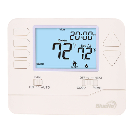
MOUNT THERMOSTAT & BATTERY INSTALL ATION Mount Thermostat subbase Align the 4 tabs on the with corresponding slots on the back of the thermostat, then push gently until the thermostat snaps in place. :.n.nn.M CLJ•LJLJ "'=="" ) Room ° Set At r,1-, -,Lr "'==""... -
Page 19: Specifications
PROGRAMMING THE THERMOSTAT Set Time Follow the steps below to set the day of the week and current time: Press MENU Press SET TIME Day of the week will be flashing. Use the key to select the current day of the week. Press NEXT STEP The current hour will be flashing.
Need help?
Do you have a question about the Master Series and is the answer not in the manual?
Questions and answers