Table of Contents
Advertisement
Quick Links
Advertisement
Table of Contents

Related Manuals for GAS GAS SM 700 2023


Summary of Contents for GAS GAS SM 700 2023
- Page 1 OWNER'S MANUAL 2023 SM 700 Art. no. 3215134en...
- Page 3 DEAR GASGAS CUSTOMER Congratulations on your decision to purchase a GASGAS motorcycle. You are now the owner of a state-of-the-art sports DEAR GASGAS CUSTOMER vehicle which, with appropriate care, will bring you pleasure for a long time to come. We wish you good and safe riding at all times! Enter the serial numbers of your vehicle below.
-
Page 4: Table Of Contents
TABLE OF CONTENTS 6.20 Closing the fuel tank filler cap..... 20 TABLE OF CONTENTS MEANS OF REPRESENTATION ........5 6.21 Combination instrument......20 Symbols used..........5 6.21.1 Overview ..........20 Formats used..........5 6.21.2 Activation and test ......... 21 6.21.3 Setting the combination instrument .. - Page 5 TABLE OF CONTENTS 10.7 Adjusting the rebound damping of the 12.10 Adding rear brake fluid ......69 shock absorber ..........44 12.11 Checking that the brake linings of the 10.8 Handlebar position........44 rear brake are secured ........ 70 10.9 Adjusting the handlebar position ...
- Page 6 TABLE OF CONTENTS CLEANING, CARE............. 100 18.1 Cleaning the motorcycle ......100 18.2 Checks and maintenance steps for winter operation ........101 STORAGE..............102 19.1 Storage............102 19.2 Preparing for use after storage....103 TROUBLESHOOTING ..........104 TECHNICAL DATA............ 106 21.1 Engine ............
-
Page 7: Means Of Representation 1
MEANS OF REPRESENTATION 1 Symbols used The meaning of specific symbols is described below. Indicates an expected reaction (e.g., of a work step or a function). Indicates an unexpected reaction (e.g., of a work step or a function). Indicates work that requires expert knowledge and technical understanding. In the interest of your own safety, have this work performed by an authorized GASGAS Motorcycles workshop. -
Page 8: Safety Advice
2 SAFETY ADVICE Use definition – intended use The vehicle is designed and constructed to withstand the usual demands of regular traffic and use on gentle terrain (un- paved roads). This vehicle is not suitable for use on race tracks. Info This vehicle is only authorized for operation on public roads in its homologated version. -
Page 9: Tampering Warning
SAFETY ADVICE 2 Tampering warning Tampering with the noise control system is prohibited. Federal law prohibits the following acts or the causing thereof: The removal or rendering inoperative by any person other than for purposes of servicing, repair, or replacement, of any device or element of design incorporated into any new vehicle for the purpose of noise control prior to its sale or delivery to the ultimate purchaser or while it is in use, or the use of the vehicle after such device or element of design has been removed or rendered inoperative by any person. -
Page 10: Work Rules
2 SAFETY ADVICE Work rules Unless specified otherwise, the ignition must be turned off during all work (models with ignition lock, models with remote key) or the engine must be at a standstill (models without ignition lock or remote key). Special tools are necessary for certain tasks. -
Page 11: Important Notes 3
IMPORTANT NOTES 3 Manufacturer warranty, implied warranty The work specified in the service schedule may only be carried out in an authorized GASGAS Motorcycles workshop and confirmed in the GASGAS Motorcycles Dealer.net, as otherwise all warranty claims will be void. Damage or secondary dam- age caused by tampering with and/or conversions on the vehicle are not covered by the manufacturer warranty. -
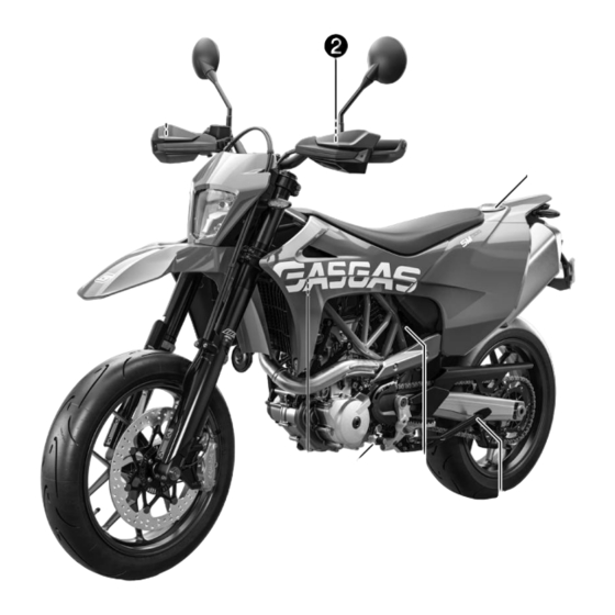
Page 12: View Of Vehicle
4 VIEW OF VEHICLE View of vehicle, front left (example) W00173-10 Hand brake lever ( p. 14) Clutch lever ( p. 14) Fuel tank filler cap Seat release ( p. 18) Side stand ( p. 19) Compression damping of the shock absorber ( p. -
Page 13: View Of Vehicle, Rear Right (Example)
VIEW OF VEHICLE 4 View of vehicle, rear right (example) V02691-10 Ignition and steering lock ( p. 17) Fork compression adjuster Light switch ( p. 15) Turn signal switch ( p. 15) Horn button ( p. 14) Combination switch ( p. -
Page 14: Serial Numbers
5 SERIAL NUMBERS Vehicle identification number The vehicle identification number is stamped on the right side of the steering head. 401945-10 Type label The Europe type label is located on the right side of the frame. V02700-10 Key number The key number can be found on the KEYCODECARD. -
Page 15: Fork Part Number
SERIAL NUMBERS 5 Fork part number The fork part number is stamped on the inner side of the fork stub. 401947-10 Shock absorber article number The shock absorber article number is on the left side of the shock absorber. 402025-10... -
Page 16: Controls
6 CONTROLS Clutch lever Clutch lever is fitted on the handlebar on the left. The clutch is activated hydraulically and adjusts itself automatically. V02755-10 Hand brake lever The hand break lever is fitted on the right side of the handlebar. The hand brake lever operates the front brake. -
Page 17: Light Switch
CONTROLS 6 Light switch The light switch is fitted on the left side of the handlebar. Possible states Low beam on – Light switch is turned downward. In this position, the low beam and tail light are switched on. High beam on – Light switch is turned upward. In this posi- tion, the high beam and tail light are switched on. -
Page 18: Abs Button
6 CONTROLS ABS button The ABS button is fitted next to the combination instrument on the left. Info The ABS button is also used as the ABS warning lamp ( p. 63). S04356-10 6.10 Combination switch The combination switch is fitted on the left side of the handlebar. Possible states STREET –... -
Page 19: Ignition And Steering Lock
CONTROLS 6 6.11 Ignition and steering lock The ignition and steering lock is located in front of the seat. Possible states Ignition off – In this position, the ignition circuit is inter- rupted, a running engine stops, and a non-running engine will not start. -
Page 20: Seat Release
6 CONTROLS 6.13 Seat release The loop unlocks the seat. Info The loop for unlocking the seat is located under the fuel tank cap. V02707-10 6.14 Grab handles The grab handles are used for moving the motorcycle around. If you carry a passenger, the passenger can hold onto the grab handles during the trip. -
Page 21: Foot Brake Lever
CONTROLS 6 The gear positions can be seen in the photograph. The neutral or idle position is between the first and second gears. 401950-11 6.17 Foot brake lever Foot brake lever is located in front of the right footrest. The rear brake is engaged with the foot brake lever. 401956-10 6.18 Side stand... -
Page 22: Closing The Fuel Tank Filler Cap
6 CONTROLS Warning Danger of poisoning Fuel is harmful to health. – Avoid skin, eye and clothing contact with fuel. – Immediately consult a doctor if you swallow fuel. – Do not inhale fuel vapors. – Rinse the affected area immediately with plenty of water in the event of contact with the skin. –... -
Page 23: Activation And Test
CONTROLS 6 6.21.2 Activation and test Activating combination instrument The combination instrument is activated when the ignition is switched Display test To enable you to check that the display is functioning properly, all dis- play segments light up briefly. S04360-01 6.21.3 Setting the combination instrument Condition... -
Page 24: Setting The Clock
6 CONTROLS – Press and hold both buttons for 3 – 5 seconds. The Setup menu is displayed. – Press the + button repeatedly until kmor mp flashes on the indica- tor. – Press the ‑ button to change from km to mp or from mp to km. –... -
Page 25: Distance 1
CONTROLS 6 6.21.7 Distance 1 – Press the + or ‑ button repeatedly until TR1 is shown on the combi- nation instrument. TR1 shows the distance 1 since the last reset, such as between two refu- eling stops. Info If the value of 9999.9 is exceeded, TR1 is automatically reset to 0.0. -
Page 26: Average Speed 2
6 CONTROLS 6.21.10 Average speed 2 – Press the + or ‑ button repeatedly until A2 is shown on the combina- tion instrument. A2 shows average speed 2 since the last reset. Briefly press Next display mode the button . Briefly press Next display mode the button . -
Page 27: Clock
CONTROLS 6 6.21.14 Clock – Press the + or ‑ button repeatedly until CLK is shown on the combi- nation instrument. CLK shows the time. S04377-01 6.21.15 Service interval display – Press the + or ‑ button repeatedly until SER is shown on the combi- nation instrument. -
Page 28: Odometer
6 CONTROLS 6.21.17 Odometer – Press the + or ‑ button repeatedly until ODO is shown on the combi- nation instrument. ODO shows the motorcycle's total mileage. S04379-01 6.21.18 Gear display The gear display shows the engaged gear. Info The gear display is at the left of the display. S04380-01 6.21.19 Service display... -
Page 29: Preparing For Use 7
PREPARING FOR USE 7 Advice on preparing for first use Danger Danger of accidents A rider who is not fit to ride poses a danger to him or herself and others. – Do not operate the vehicle if you are not fit to ride due to alcohol, drugs or medication. –... -
Page 30: Running In The Engine
7 PREPARING FOR USE Running in the engine – During the run-in phase, do not exceed the specified vehicle speed in the respective gear. Guideline During the first 1,000 km (620 mi) Maximum speed per gear First gear 50 km/h (31.1 mph) Second gear 70 km/h (43.5 mph) Third gear... - Page 31 PREPARING FOR USE 7 Warning Fire hazard The hot exhaust system may burn luggage. – Fasten your luggage in such a way that it cannot be burned or singed by the hot exhaust system. – If luggage is carried, ensure it is fixed firmly as close as possible to the center of the vehicle and ensure even weight distribution between the front and rear wheels.
-
Page 32: Riding Instructions
8 RIDING INSTRUCTIONS Checks and maintenance measures when preparing for use Info Before every trip, check the condition of the vehicle and ensure that it is roadworthy. The vehicle must be in perfect technical condition when it is being operated. –... -
Page 33: Starting Off
RIDING INSTRUCTIONS 8 – Turn the emergency OFF switch to the position . – Switch on the ignition by turning the ignition key to the position . Guideline To avoid malfunctions in the control unit communication, do not switch the ignition off and on in rapid succession. After you switch on the ignition, you can hear the fuel pump operating for about two seconds. - Page 34 8 RIDING INSTRUCTIONS Warning Risk of injury The passenger may fall from the motorcycle if they conduct themselves incorrectly. – Ensure that the passenger sits correctly on the passenger seat, places his or her feet on the passenger foot pegs and holds on to the rider or the grab handles. –...
- Page 35 RIDING INSTRUCTIONS 8 Info If unusual noises occur while riding, stop safely immediately, switch off the engine, and contact an authorized GAS- GAS Motorcycles workshop. – Shift into a higher gear when conditions allow (incline, road situa- tion, etc.). – Release the throttle while simultaneously pulling the clutch lever, shift into the next gear, release the clutch lever, and open the throt- tle.
-
Page 36: Quickshifter
8 RIDING INSTRUCTIONS Guideline Maximum speed before gear change Sixth gear to fifth gear 165 km/h (102.5 mph) Fifth gear to fourth gear 145 km/h (90.1 mph) Fourth gear to third gear 120 km/h (74.6 mph) Third gear to second gear 90 km/h (55.9 mph) Second gear to first gear 60 km/h (37.3 mph) -
Page 37: Braking
RIDING INSTRUCTIONS 8 Braking Warning Danger of accidents Moisture and dirt impair the brake system. – Brake carefully several times to dry out and remove dirt from the brake linings and the brake discs. Warning Danger of accidents A spongy pressure point on the front or rear brake reduces braking efficiency. –... -
Page 38: Stopping, Parking
8 RIDING INSTRUCTIONS Stopping, parking Warning Risk of injury People who act without authorization endanger themselves and others. – Do not leave the vehicle unattended if the engine is running. – Protect the vehicle against access by unauthorized persons. – Lock the steering and remove the ignition key if you leave the vehicle unattended. Warning Danger of burns Some vehicle components become very hot when the vehicle is operated. -
Page 39: Towing In The Event Of A Breakdown
RIDING INSTRUCTIONS 8 – Switch off the engine and remove the ignition key. – Use tension belts or other suitable devices to secure the motorcycle against accidents or falling over. 401448-01 8.10 Towing in the event of a breakdown Note Danger of damage Towing away using a towing vehicle is not an appropriate vehicle recovery method. - Page 40 8 RIDING INSTRUCTIONS Note Material damage Inadequate fuel quality causes the fuel filter to quickly become clogged. In some countries and regions, the available fuel quality and cleanliness may not be sufficient. This will result in problems with the fuel system. –...
-
Page 41: Service Schedule 9
SERVICE SCHEDULE 9 Additional information Any further work that results from the service work must be ordered separately and invoiced separately. Different service intervals may apply in your country, depending on the local operating conditions. Individual service intervals and scopes may change in the course of technical developments. The most up-to-date service schedule can always be found on GASGAS Motorcycles Dealer.net. - Page 42 9 SERVICE SCHEDULE every 48 months every 24 months every 12 months every 30,000 km (18,600 mi) every 20,000 km (12,400 mi) every 10,000 km (6,200 mi) after 1,000 km (620 mi) ● ● ● Check the valve clearance. ● ●...
-
Page 43: Tuning The Chassis 10
TUNING THE CHASSIS 10 10.1 Fork/shock absorber The fork and the shock absorber offer many options for adapting the chassis to the riding style and the payload. Info The recommendations for the suspension setting are shown in table . The table is located on the underside of the front rider's seat. -
Page 44: Compression Damping Of The Shock Absorber
10 TUNING THE CHASSIS – Turn red adjusting screw clockwise as far as it will go. Info Adjusting screw is located at the upper end of the right fork leg. The rebound damping is located in right fork leg REB (red adjusting screw). -
Page 45: Adjusting The High-Speed Compression Damping Of The Shock Absorber
TUNING THE CHASSIS 10 – Turn adjusting screw clockwise with a screwdriver as far as the last perceptible click. Info Do not loosen fitting – Turn counterclockwise by the number of clicks corresponding to the shock absorber type. Guideline V02712-10 Low-speed compression damping Comfort 20 clicks... -
Page 46: Adjusting The Rebound Damping Of The Shock Absorber
10 TUNING THE CHASSIS 10.7 Adjusting the rebound damping of the shock absorber Caution Risk of injury Parts of the shock absorber will move around if the shock absorber is detached incorrectly. The shock absorber is filled with highly compressed nitrogen. –... - Page 47 TUNING THE CHASSIS 10 – Remove screws . Take off the handlebar clamp. Take off the han- dlebar and lay it to one side. Info Cover the components to protect them against damage. Do not kink the cables and lines. –...
-
Page 48: 11 Service Work On The Chassis
11 SERVICE WORK ON THE CHASSIS 11.1 Raising the motorcycle with a lift stand Note Danger of damage The parked vehicle can roll away or fall over. – Park the vehicle on a firm and level surface. – Raise the motorcycle in the area of the footrest bracket. Neither wheel is in contact with the ground. -
Page 49: Removing The Rear Of The Motorcycle From The Wheel Stand
SERVICE WORK ON THE CHASSIS 11 11.4 Removing the rear of the motorcycle from the wheel stand Note Danger of damage The parked vehicle can roll away or fall over. – Park the vehicle on a firm and level surface. – Secure the motorcycle against falling over. -
Page 50: Cleaning The Dust Boots Of The Fork Legs
11 SERVICE WORK ON THE CHASSIS 11.7 Cleaning the dust boots of the fork legs Preparatory work – Raise the motorcycle with a lift stand. ( p. 46) – Remove fork protector. ( p. 48) Main work – Push dust boots of both fork legs downward. -
Page 51: Installing The Fork Protector
SERVICE WORK ON THE CHASSIS 11 11.9 Installing the fork protector – Position the left fork protector. Mount and tighten screws Guideline Remaining screws, 10 Nm (7.4 lbf ft) chassis – Position brake line, wiring harness, and clamp. Mount and tighten screws –... -
Page 52: Mounting The Seat
11 SERVICE WORK ON THE CHASSIS 11.12 Mounting the seat – Hook the seat using holding lugs on to bushings , lower the seat at the rear and push it forward. – Push locking pin into lock housing and push the back of the seat down until the locking pin locks in place with an audible click. -
Page 53: Storing The Tool Set
SERVICE WORK ON THE CHASSIS 11 11.14 Storing the tool set Preparatory work – Open the fuel tank filler cap. ( p. 19) – Remove the seat. ( p. 49) Main work – Remove screws Info A tool for removing and mounting these screws is located in holder on the underside of the seat. -
Page 54: Mounting Side Cover
11 SERVICE WORK ON THE CHASSIS Main work – Remove screws – Pull the left side cover out from the rubber bushing in area – Pull off the left side cover upwards from the special screw in area – Take off the left side cover from upwards. –... -
Page 55: Removing The Front Fender
SERVICE WORK ON THE CHASSIS 11 Finishing work – Mount the seat. ( p. 50) 11.17 Removing the front fender Preparatory work – Remove the headlight mask with the headlight. ( p. 84) Main work – Remove screws – Remove screws and take off the fender. -
Page 56: Installing The Air Filter
11 SERVICE WORK ON THE CHASSIS Note Engine damage Unfiltered intake air has a negative effect on the service life of the engine. Dust and dirt will enter the engine without an air filter. – Only operate the vehicle if it is equipped with an air filter. –... -
Page 57: Cleaning The Chain
SERVICE WORK ON THE CHASSIS 11 11.22 Cleaning the chain Warning Danger of accidents Lubricants on the tires reduces the road grip. – Remove lubricants from the tires using a suitable cleaning agent. Warning Danger of accidents Oil or grease on the brake discs reduces the braking effect. –... -
Page 58: Adjusting The Chain Tension
11 SERVICE WORK ON THE CHASSIS – Raise the motorcycle with the rear lifting gear. ( p. 46) Info The check is also possible when the motorcycle is resting on the side stand. – Shift the transmission to neutral position. –... -
Page 59: Checking The Chain, Rear Sprocket, Engine Sprocket, And Chain Guide
SERVICE WORK ON THE CHASSIS 11 Main work – Loosen nut – Loosen nuts – Adjust the chain tension by turning adjusting screws left and right. Guideline Chain tension 5 mm (0.2 in) Turn the adjusting screws on the left and right so that the markings on the left and right chain adjusters are in the same position relative to the reference marks... - Page 60 11 SERVICE WORK ON THE CHASSIS – Pull on the top section of the chain with the specified weight Guideline Weight of chain wear measure- 15 kg (33 lb.) ment – Measure distance of 18 chain rollers in the lower chain section. Info Chain wear is not always even, so you should repeat this measurement at different chain positions.
- Page 61 SERVICE WORK ON THE CHASSIS 11 – Check the chain sliding piece for wear. » If the lower edge of the chain pins is in line with or below the chain sliding piece: – Change the chain sliding piece. – Check that the chain sliding piece is firmly seated.
-
Page 62: Adjusting Chain Guide
11 SERVICE WORK ON THE CHASSIS 11.26 Adjusting chain guide – Remove screws . Take off the chain guide. Condition Number of teeth: ≤ 44 teeth – Insert nut in hole . Position the chain guide. – Mount and tighten screws Guideline Screw, chain guide 10 Nm (7.4 lbf ft) -
Page 63: Adjusting The Basic Position Of The Clutch Lever
SERVICE WORK ON THE CHASSIS 11 11.28 Adjusting the basic position of the clutch lever – Adjust basic position of the clutch lever to your hand size by turning adjusting screw Info Do not make any adjustments while riding. Push the clutch lever forward and turn the adjusting wheel. The range of adjustment is limited. - Page 64 11 SERVICE WORK ON THE CHASSIS – Remove screws – Take off cover with membrane – Check the fluid level. Fluid level below container rim 4 mm (0.16 in) » If the fluid level does not meet specifications: – Correct the fluid level of the hydraulic clutch. Brake fluid DOT 4 / DOT 5.1 ( p.
-
Page 65: Brake System 12
BRAKE SYSTEM 12 12.1 Anti-lock braking system (ABS) The ABS module , consisting of a hydraulic unit, an ABS control unit, and a return pump, is located under the seat. One wheel speed sen- is located in each case on the front and the rear wheel. Warning Danger of accidents Changes to the vehicle impair the func- tion of the ABS. -
Page 66: Adjusting The Basic Position Of The Hand Brake Lever
12 BRAKE SYSTEM The ABS warning lamp must light up after the ignition is switched on and go out after starting off. If it does not go out after starting off or if it lights up while riding, this indicates a malfunction in the ABS. In this case, the ABS is no longer enabled and the wheels may lock during braking. -
Page 67: Checking The Front Brake Fluid Level
BRAKE SYSTEM 12 » If the brake disc thickness is less than the specified value. – Change the brake disc. – Check the front and rear brake discs for damage, cracking, and deformation. » If the brake disc exhibits damage, cracking, or deformation: –... -
Page 68: Checking That The Brake Linings Of The Front Brake Are Secured
12 BRAKE SYSTEM Warning Danger of accidents Old brake fluid reduces the braking effect. – Make sure that brake fluid for the front and rear brake is changed in accordance with the service schedule. (Your authorized GASGAS Motorcycles workshop will be glad to help.) Note Environmental hazard Hazardous substances cause environmental damage. -
Page 69: Checking The Free Travel Of Foot Brake Lever
BRAKE SYSTEM 12 – Check the brake linings for lining thickness ≥ 1 mm (≥ 0.04 in) Minimum thickness » If it is less than the minimum thickness: – Change the brake linings of the front brake. – Check the brake linings for damage and cracking. »... -
Page 70: Checking The Rear Brake Fluid Level
12 BRAKE SYSTEM – Loosen fittings on foot brake cylinder – To adjust the basic position of the foot brake lever to individual requirements, loosen nut and turn screw accordingly. Info The range of adjustment is limited. The screw must be screwed into the footrest bracket by at least four turns. -
Page 71: Adding Rear Brake Fluid
BRAKE SYSTEM 12 12.10 Adding rear brake fluid Warning Danger of accidents An insufficient brake fluid level will cause the brake system to fail. If the brake fluid level drops below the MIN marking, the brake system is leaking or the brake linings are worn down. -
Page 72: Checking That The Brake Linings Of The Rear Brake Are Secured
12 BRAKE SYSTEM 12.11 Checking that the brake linings of the rear brake are secured Warning Danger of accidents Worn-out brake linings reduce the braking effect. – Ensure that worn-out brake linings are replaced immediately. (Your authorized GASGAS Motorcycles workshop will be glad to help.) Warning Danger of accidents Damaged brake discs reduce the braking effect. -
Page 73: Wheels, Tires 13
WHEELS, TIRES 13 13.1 Removing the front wheel Preparatory work – Raise the motorcycle with the rear lifting gear. ( p. 46) – Lift the motorcycle with the front lifting gear. ( p. 47) Main work – Remove screw and pull wheel speed sensor out of the hole. - Page 74 13 WHEELS, TIRES Main work – Check the wheel bearing for damage and wear. » If the wheel bearing is damaged or worn: – Change front wheel bearing. – Clean and grease shaft seal rings and contact surfaces of the spacers.
-
Page 75: Removing The Rear Wheel
WHEELS, TIRES 13 Finishing work – Remove the rear of the motorcycle from the wheel stand. ( p. 47) 13.3 Removing the rear wheel Preparatory work – Raise the motorcycle with the rear lifting gear. ( p. 46) Main work –... -
Page 76: Installing The Rear Wheel
13 WHEELS, TIRES 13.4 Installing the rear wheel Warning Danger of accidents Oil or grease on the brake discs reduces the braking effect. – Always keep the brake discs free of oil and grease. – Clean the brake discs with brake cleaner when necessary. Warning Danger of accidents There is no braking effect to start with at the rear brake after installing the rear wheel. -
Page 77: Checking The Rear Hub Damping Rubber Pieces
WHEELS, TIRES 13 – Mount and tighten screw Guideline Screw, wheel 6 Nm (4.4 lbf ft) speed sensor Loctite ® 243™ – Position the brake line in the guide. – Operate the foot brake lever repeatedly until the brake linings are in contact with the brake disc and there is a pressure point. -
Page 78: Checking The Tire Condition
13 WHEELS, TIRES Finishing work – Install the rear wheel. p. 74) – Remove the rear of the motorcycle from the wheel stand. ( p. 47) – Check the chain tension. ( p. 55) 13.6 Checking the tire condition Warning Danger of accidents If a tire bursts while riding, the vehicle becomes uncontrollable. -
Page 79: Checking Tire Pressure
WHEELS, TIRES 13 – Check the tire age. Info The tire date of manufacture is usually contained in the tire label and is indicated by the last four digits of the DOT num- ber. The first two digits indicate the week of manufacture and the last two digits the year of manufacture. -
Page 80: 14 Electrical System
14 ELECTRICAL SYSTEM 14.1 Removing the 12-V battery Warning Risk of injury Battery acid and battery gases cause serious chemical burns. – Keep 12 V batteries out of the reach of children. – Wear suitable protective clothing and safety glasses. – Avoid contact with battery acid and battery gases. -
Page 81: Charging The 12-V Battery
ELECTRICAL SYSTEM 14 – Position positive cable with washer – Position negative cable with washer – Mount and tighten the screw. Guideline Screw, battery terminal M6 4.5 Nm (3.32 lbf ft) V02750-10 – Position positive terminal cover – Position retaining bracket and mount and tighten screws Guideline Remaining screws, 10 Nm (7.4 lbf ft) -
Page 82: Changing The Main Fuse
14 ELECTRICAL SYSTEM Info Even when there is no load on the 12-V battery, it discharges steadily each day. The charging level and the method of charging are very important for the service life of the 12-V battery. Rapid recharging with a high charging current shortens the service life of the battery. If the charging current, charging voltage, or charging time is exceeded, electrolyte escapes through the safety valves. -
Page 83: Changing The Abs Fuses
ELECTRICAL SYSTEM 14 Preparatory work – Open the fuel tank filler cap. ( p. 19) – Remove the seat. ( p. 49) Main work – Pull off engine control unit from the holder and hang to the side. – Take off protection caps V02739-10 –... -
Page 84: Changing The Fuses Of Individual Electrical Power Consumers
14 ELECTRICAL SYSTEM To change the fuse of the ABS hydraulic unit: – Take off protection cap – Remove the fuse of the ABS hydraulic unit. – Insert a new fuse. Fuse (75011088010) ( p. 111) – Mount the protection cap. To change the fuse of the ABS return pump: –... - Page 85 ELECTRICAL SYSTEM 14 – Remove the faulty fuse. Guideline Fuse 1 - 10 A - ignition, combination instrument, clock, engine control unit Fuse 2 - 10 A - ignition, combination instrument, engine control unit Fuse 3 - 10 A - fuel pump Fuse 4 - 10 A - radiator fan Fuse 5 - 10 A - horn, brake light, turn signal S04583-10...
-
Page 86: Removing The Headlight Mask With The Headlight
14 ELECTRICAL SYSTEM 14.7 Removing the headlight mask with the headlight – Cover the fender with a cloth. – Remove screws on both sides. – Tip the headlight mask forward. V02740-10 – Disconnect plug-in connector of the headlight. – Take off the headlight mask. S03304-10 14.8 Installing the headlight mask with the headlight... -
Page 87: Changing The Headlight Bulb
ELECTRICAL SYSTEM 14 Finishing work – Check the headlight setting. ( p. 86) 14.9 Changing the headlight bulb Note Impairments to reflectors and lamps Grease on the reflector reduces the emitted light. Grease on the bulb will evaporate due to the heat and be deposited on the reflector. Grease residue on the bulb reduces heat dissipation and increases the heat of the bulb, thus reducing its service life. -
Page 88: Checking The Headlight Setting
14 ELECTRICAL SYSTEM Main work – Remove bulb socket V02741-11 – Pull position light lamp out of the bulb socket. – Insert a new position light lamp in the bulb socket. Position light (W5W / socket W2.1x9.5d) ( p. 111) –... -
Page 89: Adjusting The Headlight Range
ELECTRICAL SYSTEM 14 14.12 Adjusting the headlight range Preparatory work – Check the headlight setting. ( p. 86) Main work – Loosen screw – Adjust the headlight range by pivoting the headlight. Guideline The boundary between light and dark must be exactly on the lower mark for a motorcycle with rider (instructions on how to apply the mark: Checking the headlight setting). -
Page 90: 15 Cooling System
15 COOLING SYSTEM 15.1 Cooling system Water pump in the engine ensures forced circulation of the coolant. The pressure resulting from the warming of the cooling system is reg- ulated by a valve in radiator cap . Heat expansion causes excess coolant to flow into compensating tank . -
Page 91: Checking The Coolant Level
COOLING SYSTEM 15 – Place the motorcycle on a horizontal surface using the side stand. – Remove the cover of compensating tank – Check the antifreeze in the coolant. −25 … −45 °C (−13 … −49 °F) » If the antifreeze in the coolant does not match the specified value: –... -
Page 92: Draining The Coolant
15 COOLING SYSTEM Condition The engine is cold. – Place the motorcycle on a horizontal surface using the side stand. – Check the coolant level in compensating tank The coolant level must be between the two markings. » If the coolant level does not match the specified value: –... -
Page 93: Filling/Bleeding The Cooling System
COOLING SYSTEM 15 – Position the motorcycle upright. – Position an appropriate container under the engine. – Remove screw . Take off the radiator cap. – Completely drain the coolant. – Mount and tighten screw with a new seal ring. Guideline Screw plug, water M10x1... -
Page 94: Changing The Coolant
15 COOLING SYSTEM 15.6 Changing the coolant Warning Danger of scalding During motorcycle operation, the coolant gets very hot and is under pressure. – Do not open the radiator, the radiator hoses or other cooling system components if the engine or the cooling system are at operating temperature. - Page 95 COOLING SYSTEM 15 – Stand the motorcycle on a level surface using the side stand. – Refill with coolant. Coolant 1.20 l (1.27 qt.) Coolant ( p. 116) – Completely fill the radiator with coolant. – Mount radiator cap V02747-10 –...
-
Page 96: 16 Tuning The Engine
16 TUNING THE ENGINE 16.1 Changing the riding mode Info The desired riding mode can be activated via the MAP button on the combination switch. The setting most recently selected is activated again when restarting. The riding mode can also be changed during the ride. Condition Throttle grip closed. -
Page 97: Checking The Basic Position Of The Shift Lever
TUNING THE ENGINE 16 16.3 Checking the basic position of the shift lever Info When driving, the shift lever must not touch the rider's boot when in the basic position. If the shift lever is permanently touching the boot, the transmission will be subject to excessive load; this can cause a malfunction of the quickshifter (optional). -
Page 98: 17 Service Work On The Engine
17 SERVICE WORK ON THE ENGINE 17.1 Checking the engine oil level Info The engine oil level must be checked when the engine is warm. Condition The engine is at operating temperature. Preparatory work – Stand the motorcycle upright on a horizontal surface. Main work –... - Page 99 SERVICE WORK ON THE ENGINE 17 – Thoroughly clean the oil drain plug with magnet. – Mount the oil drain plug with the magnet and seal ring and tighten Guideline Oil drain plug with M12x1.5 20 Nm (14.8 lbf ft) magnet S02209-01 –...
- Page 100 17 SERVICE WORK ON THE ENGINE – Position oil screen with the O-rings. – Mount and tighten screw plug with the O-ring. Guideline Plug, oil screen M20x1.5 15 Nm (11.1 lbf ft) S03324-10 – Position oil screen with the O-rings. –...
-
Page 101: Adding Engine Oil
SERVICE WORK ON THE ENGINE 17 17.3 Adding engine oil Info Too little engine oil or poor-quality engine oil will result in premature wear of the engine. Main work – Remove filler plug with the O-ring, and fill up with engine oil. –... -
Page 102: 18 Cleaning, Care
18 CLEANING, CARE 18.1 Cleaning the motorcycle Note Material damage Components become damaged or destroyed if a pressure cleaner is used incorrectly. The high pressure forces water into the electrical components, connectors, throttle cables, and bearings, etc. Pressure which is too high causes malfunctions and destroys components. –... -
Page 103: Checks And Maintenance Steps For Winter Operation
CLEANING, CARE 18 – After the motorcycle has cooled down, lubricate all moving parts and pivot points. – Clean the chain. ( p. 55) – Treat bare metal (except for brake discs and the exhaust system) with a corrosion inhibitor. Preserving materials for paints, metal and rubber ( p. -
Page 104: 19 Storage
19 STORAGE 19.1 Storage Warning Danger of poisoning Fuel is harmful to health. – Avoid skin, eye and clothing contact with fuel. – Immediately consult a doctor if you swallow fuel. – Do not inhale fuel vapors. – Rinse the affected area immediately with plenty of water in the event of contact with the skin. –... -
Page 105: Preparing For Use After Storage
STORAGE 19 19.2 Preparing for use after storage – Take the motorcycle off the front lifting gear. ( p. 47) – Remove the rear of the motorcycle from the wheel stand. ( p. 47) – Charge the 12-V battery. p. 79) –... -
Page 106: 20 Troubleshooting
20 TROUBLESHOOTING Faults Possible cause Action – The engine does not turn when Operating error Carry out start procedure. ( p. 30) the start button is pressed – 12 V battery discharged Charge the 12-V battery. p. 79) – Check the open-circuit current. –... - Page 107 TROUBLESHOOTING 20 Faults Possible cause Action – High oil consumption Engine oil too thin (low viscosity) Change the engine oil and the oil filter, clean the oil screens. p. 96) – Headlight and parking light are not Fuse 6 blown Change the fuses of individual electrical functioning power consumers.
-
Page 108: 21 Technical Data
21 TECHNICAL DATA 21.1 Engine Design 1-cylinder 4-stroke engine, water-cooled Displacement 692.7 cm³ (42.271 cu in) Stroke 80 mm (3.15 in) Bore 105 mm (4.13 in) Compression ratio 12.7:1 Idle speed Coolant temperature: ≥ 70 °C (≥ 158 °F) 1,650 ± 50 rpm Control OHC, intake with cam levers, exhaust controlled by rocker arm, chain drive... -
Page 109: Engine Tightening Torques
TECHNICAL DATA 21 21.2 Engine tightening torques Screw, membrane fixation 2 Nm (1.5 lbf ft) Loctite ® 243™ Hose clamp, intake flange 2.5 Nm (1.84 lbf ft) Oil nozzle for clutch lubrication 0.4 Nm (0.3 lbf ft) Oil nozzle for conrod bearing lubrica- 0.8 Nm (0.59 lbf ft) tion Locking screw for bearing... - Page 110 21 TECHNICAL DATA Screw, engine case 10 Nm (7.4 lbf ft) Screw, engine case M6x25 10 Nm (7.4 lbf ft) Screw, engine case M6x30 10 Nm (7.4 lbf ft) Screw, engine case M6x70 10 Nm (7.4 lbf ft) Screw, engine case M6x80 10 Nm (7.4 lbf ft) Screw, engine sprocket cover and...
-
Page 111: Capacities
TECHNICAL DATA 21 Screw, cylinder head Tightening sequence: Tighten diagonally, beginning with the rear screw on the timing chain shaft. 1st stage 15 Nm (11.1 lbf ft) 2nd stage 30 Nm (22.1 lbf ft) 3rd stage 45 Nm (33.2 lbf ft) 4th stage 60 Nm (44.3 lbf ft) Thread greased... -
Page 112: Fuel
21 TECHNICAL DATA 21.3.3 Fuel Please observe the labels on EU fuel pumps. A00420-10 Fuel tank capacity, approx. 13.3 l (3.51 US gal) Super unleaded (ROZ 95) ( p. 117) Fuel reserve, approx. 1.4 l (1.5 qt.) 21.4 Chassis Frame Lattice frame made of chrome molybdenum steel tubing, powder-coated Fork... -
Page 113: Electrical System
TECHNICAL DATA 21 Maximum permissible overall weight 350 kg (772 lb.) 21.5 Electrical system 12-V battery YTZ10S Battery voltage: 12 V Nominal capacity: 8.6 Ah Maintenance-free Fuse 58011109130 30 A Fuse 75011088015 15 A Fuse 75011088010 10 A Fuse 75011088025 25 A Headlight H4/socket P43t... -
Page 114: Shock Absorber
21 TECHNICAL DATA 21.8 Shock absorber Shock absorber article number 15.18.7S.12 Shock absorber WP Suspension APEX 5746 High-speed compression damping Comfort 2 turns Standard 1.5 turns Sport 1 turn Full payload 1 turn Low-speed compression damping Comfort 20 clicks Standard 15 clicks Sport 10 clicks... - Page 115 TECHNICAL DATA 21 Screw, headlight mask 2 Nm (1.5 lbf ft) Screw, heat guard on fuel tank cover M5x12 3.5 Nm (2.58 lbf ft) Screw, pressure regulator 4 Nm (3 lbf ft) Screw, radiator fan cover 3.2 Nm (2.36 lbf ft) Screw, radiator guard 3.5 Nm (2.58 lbf ft) Screw, seat lock cable...
- Page 116 21 TECHNICAL DATA Screw, radiator shield M6x20 4.5 Nm (3.32 lbf ft) Screw, SAS valve 4 Nm (3 lbf ft) Screw, seat lock 5 Nm (3.7 lbf ft) Screw, seat support M6x12 5 Nm (3.7 lbf ft) Screw, seat support, front M6x14 6 Nm (4.4 lbf ft) Screw, side fuel tank cover...
- Page 117 TECHNICAL DATA 21 Screw, rear brake disc 30 Nm (22.1 lbf ft) Loctite ® 243™ Screw, rear footrest bracket M8x16 25 Nm (18.4 lbf ft) Screw, side stand bracket 25 Nm (18.4 lbf ft) Loctite ® 243™ Screw, spring holder plate on side 25 Nm (18.4 lbf ft) stand bracket Loctite...
-
Page 118: 22 Substances
22 SUBSTANCES Brake fluid DOT 4 / DOT 5.1 Standard/classification – Guideline – Use only brake fluid that complies with the specified standard (see specifications on the container) and that exhibits the corresponding properties. Recommended supplier Castrol – REACT PERFORMANCE DOT 4 MOTOREX ®... - Page 119 SUBSTANCES 22 Recommended supplier MOTOREX ® – Racing Fork Oil Shock absorber fluid (SAE 2.5) (50180751S1) Standard/classification – SAE ( p. 119) (SAE 2.5) Guideline – Use only oils that comply with the specified standards (see specifications on the container) and that exhibit the corre- sponding properties.
-
Page 120: 23 Auxiliary Substances
23 AUXILIARY SUBSTANCES Chain cleaner Recommended supplier MOTOREX ® – Chain Clean Fuel additive Recommended supplier MOTOREX ® – Fuel Stabilizer Long-life grease Recommended supplier MOTOREX ® – Bike Grease 2000 Motorcycle cleaner Recommended supplier MOTOREX ® – Moto Clean Perfect finish and high gloss polish for paints Recommended supplier MOTOREX... -
Page 121: Standards 24
STANDARDS 24 JASO T903 MA2 Different technical development directions required a separate specification for motorcycles – the JASO T903 MA2 stan- dard. Earlier, engine oils from the automobile industry were used for motorcycles because there was no separate motorcycle specification. Whereas long service intervals are demanded for automobile engines, the focus for motorcycle engines is on high perfor- mance at high engine speeds. -
Page 122: 25 Index Of Special Terms
25 INDEX OF SPECIAL TERMS Anti-lock braking system Safety system that prevents locking of the wheels when driving straight ahead without the influence of lateral forces Motorcycle Traction Control Auxiliary function of the motor control that reduces engine torque with spinning rear wheel On-board diagnosis Vehicle system, which monitors the specified parameters of the vehicle electronics... -
Page 123: List Of Abbreviations 26
LIST OF ABBREVIATIONS 26 Art. no. Article number circa compare e.g. for example etc. et cetera i.a. inter alia number poss. possibly... -
Page 124: 27 List Of Symbols
27 LIST OF SYMBOLS 27.1 Red symbols Red symbols indicate an error condition that requires immediate intervention. The coolant temperature warning lamp lights up red – The coolant temperature has reached a criti- cal value. Stop immediately (taking care not to endanger yourself or other road users in the process), switch off the engine, allow it to cool down and check the coolant level. -
Page 125: Index
INDEX Chain tension INDEX adjusting ......56 checking ......55 12-V battery Changing the headlight bulb . - Page 126 INDEX removing ......48 Motorcycle traction control ....34 Front fender installing .
- Page 127 INDEX Shock absorber ......compression damping, general ... . 42 Winter operation high-speed compression damping, adjusting .
- Page 128 *3215134en* 3215134en 21.11.2022 Stallhofnerstraße 3 / 5230 Mattighofen / Austria / http://www.gasgas.com...
Need help?
Do you have a question about the SM 700 2023 and is the answer not in the manual?
Questions and answers