Garmin GPS 175 Maintenance Manual
Part 23 aml stc
Hide thumbs
Also See for GPS 175:
- Pilot's manual (244 pages) ,
- Service bulletin (10 pages) ,
- Pilot's manual (220 pages)
Table of Contents
Advertisement
GPS 175/GNX 375/GNC 355
Part 23 AML STC
Maintenance Manual
with Instructions for Continued Airworthiness
for STC SA02636SE
Aircraft make, model, registration number, and serial number, along
with the applicable STC configuration information, must be
completed in Appendix A and saved with aircraft permanent records.
190-02207-A2
March 2023
Revision 3
Advertisement
Chapters
Table of Contents
Troubleshooting

Related Manuals for Garmin GPS 175


Summary of Contents for Garmin GPS 175
- Page 1 GPS 175/GNX 375/GNC 355 Part 23 AML STC Maintenance Manual with Instructions for Continued Airworthiness for STC SA02636SE Aircraft make, model, registration number, and serial number, along with the applicable STC configuration information, must be completed in Appendix A and saved with aircraft permanent records.
- Page 2 Garmin. The Bluetooth® word mark and logos are registered trademarks owned by Bluetooth SIG, Inc. and any use of such marks by Garmin is under license. Other trademarks and trade names are those of their respective owners. Windows® is a registered trademark of Microsoft Corporation in the United States and other countries.
- Page 3 The AES file encryption software is provided “as is” with no explicit or implied warranties in respect of its properties, including, but not limited to, correctness and/or fitness for purpose. 190-02207-A2 GPS 175/GNX 375/GNC 355 Part 23 AML STC Maintenance Manual Rev. 3 Page ii...
- Page 4 Software License Agreement (hereinafter the “Agreement”) and is subject to the following terms and conditions which are agreed to by End User (“Licensee”, “you” or “your”), on the one hand, and Garmin and its licensors and affiliated companies of Garmin and its licensors, on the other hand. The Licensed Software is licensed, not sold, to you. Garmin and Licensee may be referred to individually as a “Party”...
- Page 5 General. No Devices or Services. Licensee acknowledges and agrees that nothing in this Agreement shall be construed as requiring Garmin to: (a) provide or supply the Devices or any other devices or hardware to Licensee; (b) grant any 190-02207-A2 GPS 175/GNX 375/GNC 355 Part 23 AML STC Maintenance Manual Rev.
- Page 6 Assignment. Licensee may not assign this Agreement or any of its rights, interests or obligations hereunder without the prior written consent of Garmin. Any purported assignment in violation of this Section 6.3 shall be null and void. Subject to the foregoing, this Agreement shall be binding upon and shall inure to the benefit of the Parties and their respective successors and permitted assigns and transferees.
- Page 7 CURRENT REVISION DESCRIPTION Section Change Description Page ii Updated software license agreement. Updated Figure 2-1 GPS 175 System Diagram to include interface to Fuel/Air Data 2.1.1 computers. Updated Figure 2-2 GNX 375 System Diagram to include interface to Fuel/Air Data 2.1.2 computers.
- Page 8 Cleaners containing ammonia will harm the anti-reflective coating. Clean the display with a clean, lint-free cloth and a cleaner that is safe for anti-reflective coatings. 190-02207-A2 GPS 175/GNX 375/GNC 355 Part 23 AML STC Maintenance Manual Rev. 3 Page vii...
-
Page 9: Table Of Contents
SYSTEM CONFIGURATION AND CHECKOUT ..............8-1 Overview ...........................8-2 System Checkout ........................8-2 GPS 175/GNX 375/GNC 355 Configuration ................8-2 Regulatory Test (GNX 375) ......................8-2 ADS-B Out Test (GNX 375) .....................8-3 190-02207-A2 GPS 175/GNX 375/GNC 355 Part 23 AML STC Maintenance Manual Rev. 3 Page viii... - Page 10 RETURN-TO-SERVICE PROCEDURE ..................9-1 Maintenance Records ........................9-1 APPENDIX A AIRCRAFT & INSTALLATION SPECIFIC INFORMATION ......A-1 190-02207-A2 GPS 175/GNX 375/GNC 355 Part 23 AML STC Maintenance Manual Rev. 3 Page ix...
- Page 11 Figure 6-2 GNX 375 Rack Installation ....................6-5 Figure 6-3 GNC 355 Rack Installation ....................6-7 Figure 6-4 Configuration Module Assembly ..................6-9 Figure 6-5 GAE Assembly ........................6-10 190-02207-A2 GPS 175/GNX 375/GNC 355 Part 23 AML STC Maintenance Manual Rev. 3 Page x...
- Page 12 Table 5-5 J3751 Connector Pinout ......................5-26 Table 5-6 J3752 Connector Pinout ......................5-27 Table 5-7 J3551 Connector Pinout ......................5-29 Table 5-8 J3552 Connector Pinout ......................5-30 Table 6-1 Instrument Test Data .......................6-8 190-02207-A2 GPS 175/GNX 375/GNC 355 Part 23 AML STC Maintenance Manual Rev. 3 Page xi...
- Page 13 1 INTRODUCTION Content, Scope, and Purpose ......................1-2 Organization............................1-2 Applicability .............................1-3 Publications............................1-3 Revision and Distribution .........................1-3 Reference ............................1-4 1.6.1 Terminology ..........................1-4 1.6.2 Acronyms ...........................1-4 190-02207-A2 GPS 175/GNX 375/GNC 355 Part 23 AML STC Maintenance Manual Rev. 3 Page 1-1...
-
Page 14: Content, Scope, And Purpose
This document provides Instructions for Continued Airworthiness (ICA) and Maintenance Manual (MM) for the GPS 175, GNX 375, and GNC 355 as installed under STC SA02636SE. The installation of the GPS 175, GNX 375, GNC 355, and associated wiring is performed in accordance with their respective installation manual listed in Table 1-1. -
Page 15: Applicability
1.3 Applicability This document applies to all aircraft with either the GPS 175, GNX 375, or the GNC 355 installed in accordance with STC SA02636SE. Modification of an aircraft by this STC obligates the aircraft operator to include the maintenance information provided by this document in the operator’s Aircraft Maintenance Manual and the operator's Aircraft Scheduled Maintenance Program. -
Page 16: Reference
VCDI: Vertical Course Deviation Indicator Airworthiness ID: Identifier WAAS: Wide Area Augmentation System IFR: Instrument Flight Rules XM: XM Satellite Radio LED: Light Emitting Diode XPRD: Transponder 190-02207-A2 GPS 175/GNX 375/GNC 355 Part 23 AML STC Maintenance Manual Rev. 3 Page 1-4... -
Page 17: System Description
2 SYSTEM DESCRIPTION Equipment Descriptions........................2-2 2.1.1 GPS 175............................2-2 2.1.2 GNX 375 ............................2-3 2.1.3 GNC 355 ............................2-4 2.1.4 Flight Stream 510 ........................2-5 2.1.5 GAE 12............................2-5 190-02207-A2 GPS 175/GNX 375/GNC 355 Part 23 AML STC Maintenance Manual Rev. 3 Page 2-1... -
Page 18: Equipment Descriptions
(LPV) when interfaced with a CDI. The GPS 175 is also a certified ADS-B Out position source. The bezel of the GPS 175 is 2 inches x 6.25 inches and is designed to fit in the same location as older 2-inch avionics, such as GNC 255 or GTR 225. -
Page 19: Figure 2-2 Gnx 375 System Diagram
Power/home button, dual concentric rotary knob with push entry, SD card slot, and photocell. The GNX 375 has the same capabilities as the GPS 175, plus a Mode S transponder and ADS-B receiver. The internal AHRS sensor cannot be used to drive anything other than the display of attitude on a non-certified PED. -
Page 20: Figure 2-3 Gnc 355 System Diagram
Power/home button, dual concentric rotary knob with push entry, SD card slot, and photocell. The GNC 355 has the same capabilities as the GPS 175, plus a VHF COM radio. The GNC 355 has a 25 kHz spacing radio and the GNC 355A has a 8.33 kHz spacing radio. -
Page 21: Figure 2-4 Flight Stream 510
The Flight Stream 510 is a wireless-enabled data card that is inserted into the SD card slot. The Flight Stream 510 interfaces to the GPS 175/GNX 375/GNC 355 by replacing the front-loaded data card to allow wireless database transfer with PEDs over WiFi. -
Page 22: Control And Operation
3.4.7 SD Load............................3-11 Control and operation of the GPS 175, GNX 375, and GNC 355 occurs through the use of the touch display, dual rotary knob, and the Home/Power key. The home page, shown in Figure 3-1, Figure 3-2, and Figure 3-3, is the first page displayed after the startup prompts. -
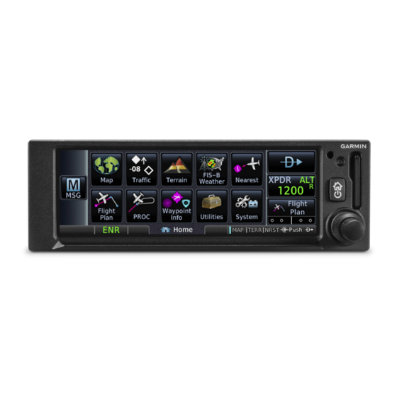
Page 23: Figure 3-1 Gps 175 Home Page
3.1 GPS 175 The GPS 175 home page is shown in Figure 3-1, which contains labels identifying key aspects of the GPS 175 features and controls. These features and controls are as follows: • Function Keys - Touch the function keys to access the features or pages described on the key. -
Page 24: Figure 3-2 Gnx 375 Home Page
Dual Rotary Knob Function Hints - This area of the screen provides more detailed information on the operation of the dual concentric knobs for the given page. Figure 3-2 GNX 375 Home Page 190-02207-A2 GPS 175/GNX 375/GNC 355 Part 23 AML STC Maintenance Manual Rev. 3 Page 3-3... -
Page 25: Gnc 355
Dual Rotary Knob Function Hints - This area of the screen provides more detailed information on the operation of the dual concentric knobs for the given page. Figure 3-3 GNC 355 Home Page 190-02207-A2 GPS 175/GNX 375/GNC 355 Part 23 AML STC Maintenance Manual Rev. 3 Page 3-4... -
Page 26: Configuration Mode Overview
The Configuration mode home page is the first page that is displayed in this mode. For detailed information on configuring the GPS 175, refer to GPS 175 Part 23 AML STC Installation Manual (P/N 190-02207-A1). For detailed information on configuring the GNX 375, refer to GNX 375 Part 23 AML STC Installation Manual (P/N 190-02207-A4). -
Page 27: Figure 3-5 Setup Page
The GI 275 toggle button indicates whether or not a GI 275 is Present or Not Present in the installation. 3.4.3.1.6 Cross-Side Navigator The Cross-Side Navigator button allows the selection of a cross-side navigator. 190-02207-A2 GPS 175/GNX 375/GNC 355 Part 23 AML STC Maintenance Manual Rev. 3 Page 3-6... - Page 28 This page also allows the configuration of the photocell and the lighting bus settings. 3.4.3.3 Main System The Main System allows the user to configure system related settings for the GPS 175/GNX 375/ GNC 355. Page settings include the following: •...
-
Page 29: Diagnostics
Each port is chosen for display by touching the ARINC 429 Port button to toggle between the input ports. Select a port to display. The GPS 175/GNX 375/GNC 355 will then display the label, SSM, Data, and SDI for each ARINC 429 packet received by the selected port. This is useful for determining if the expected labels are being received and for troubleshooting incorrect or swapped wiring to the input ports. - Page 30 3.4.4.4 Discrete Outputs The Discrete Outputs page displays the state of each of the discrete outputs on the GPS 175/GNX 375/ GNC 355. This page also allows for the discrete outputs to be toggled between the Active and Inactive states. This is useful for ensuring that these signals output are properly connected to annunciator lights or other LRUs and that they are receiving the signal.
-
Page 31: Feature Enablement
1. Insert an SD card into the card slot. 2. Power on the unit in Configuration mode. 3. Touch the SD Save button. 4. Touch the OK button to acknowledge a successful export. 190-02207-A2 GPS 175/GNX 375/GNC 355 Part 23 AML STC Maintenance Manual Rev. 3 Page 3-10... -
Page 32: Sd Load
3. Touch the SD Load button. 4. Select a file to load. 5. Restart the unit. 6. Verify settings on Interface Settings page are correct. 190-02207-A2 GPS 175/GNX 375/GNC 355 Part 23 AML STC Maintenance Manual Rev. 3 Page 3-11... -
Page 33: Instructions For Continued Airworthiness
Special Tools ..........................4-3 Maintenance Intervals........................4-4 Visual Inspection ..........................4-5 Electrical Bonding Test ........................4-6 4.5.1 GPS 175/GNX 375/GNC 355 Bonding Check (Metallic or Tube-and-Fabric Aircraft) ...4-6 4.5.2 GPS 175/GNX 375/GNC 355 Bonding Check (Composite Aircraft)........4-6 Overhaul Period ..........................4-7 Additional Instructions ........................4-7 190-02207-A2 GPS 175/GNX 375/GNC 355 Part 23 AML STC Maintenance Manual Rev. -
Page 35: Servicing Information
4.2 Servicing Information The GPS 175, GNX 375, and GNC 355 do not require servicing. In the event of system failure, troubleshoot the GPS 175/GNX 375 in accordance with Section 5. 4.2.1 Periodic Maintenance The GPS 175/GNX 375/GNC 355 are designed to detect internal failures. A thorough self-test is executed automatically upon application of power to the units. -
Page 36: Maintenance Intervals
Removal and reinstallation of the GPS 175/GNX 375/ On Condition and Replacement GNC 355 LRUs. The GPS 175,GNX 375 and GNC 355 display and bezel may be cleaned periodically. The front bezel and display should be cleaned with a soft Cleaning On Condition cotton cloth dampened with clean water. -
Page 37: Visual Inspection
4.4 Visual Inspection Conduct a visual inspection of the GPS 175/GNX 375/GNC 355 unit(s), switches, Flight Stream 510, and their wiring harnesses to ensure that they continue to comply with the STC SA02636SE. 1. Inspect the GPS 175/GNX 375/GNC 355 unit for security of attachment, including visual inspection of mounting racks and other supporting structure attaching the racks to aircraft instrument panel. -
Page 38: Electrical Bonding Test
5 mΩ. In the event of bonding test failure, remove the GPS 175/GNX 375/GNC 355 rack, clean the attachment points with a bonding brush at both the rack and the aircraft, and re-attach the rack to the rails in the panel. -
Page 39: Overhaul Period
The system does not require overhaul at a specific time period. Power on self-test and BIT will monitor the health of the GPS 175/GNX 375/GNC 355 system. If any LRU indicates an internal failure, the unit may be removed and replaced. Refer to Section 5 of this document for fault corrective actions. -
Page 40: Troubleshooting
5.4.1 J3751 62-Pin HD-DSub ......................5-25 5.4.2 J3752 44-Pin HD-DSub ......................5-27 GNC 355 Connector Pinout Information..................5-28 5.5.1 J3551 62-Pin HD-DSub ......................5-28 5.5.2 J3552 44-Pin HD-DSub ......................5-30 190-02207-A2 GPS 175/GNX 375/GNC 355 Part 23 AML STC Maintenance Manual Rev. 3 Page 5-1... -
Page 41: General Troubleshooting
This section provides information to assist troubleshooting if problems occur after completing the maintenance. Refer to the GPS 175/GNX 375/GNC 355 System Configuration Log retained in the aircraft permanent records for system configuration data. When troubleshooting the GPS 175, GNX 375, or GNC 355 system, refer to the wire routing drawings and interconnect wiring diagrams that are retained in the aircraft permanent records. -
Page 42: Table 5-2 Gnx 375 General Troubleshooting Guide
Incorrect Mode S Check the Flight ID Configuration aircraft data Incorrect Flight ID configuration. page and verify the settings are transmitted. configured correctly. 190-02207-A2 GPS 175/GNX 375/GNC 355 Part 23 AML STC Maintenance Manual Rev. 3 Page 5-3... -
Page 43: Table 5-3 Gnc 355 General Troubleshooting Guide
GNC 355 can be monitored on the system (ARINC 429 ARINC Inputs page found on the heading input). Wiring connections are incorrect. Diagnostics page. Refer to Section 3.4.4.1. Check wiring connections. 190-02207-A2 GPS 175/GNX 375/GNC 355 Part 23 AML STC Maintenance Manual Rev. 3 Page 5-4... - Page 44 Wrong type of headsets or sidetone level is too low or Sidetone adjustment is found on the level needs adjustment. too high. COM Setup Config Mode page. 190-02207-A2 GPS 175/GNX 375/GNC 355 Part 23 AML STC Maintenance Manual Rev. 3 Page 5-5...
-
Page 45: Failure Annunciations
5.2 Failure Annunciations If data fields become invalid, the GPS 175/GNX 375/GNC 355 typically annunciates the failures with a large red “X”, as shown in Figure 5-1. Figure 5-1 Failure Screen 190-02207-A2 GPS 175/GNX 375/GNC 355 Part 23 AML STC Maintenance Manual Rev. -
Page 46: Figure 5-2 Gps 175/Gnx 375/Gnc 355 System Alert Troubleshooting
Reload software, Reload software, If faults still exist, contact Garmin. Figure 5-2 GPS 175/GNX 375/GNC 355 System Alert Troubleshooting Sheet 1 of 2 190-02207-A2 GPS 175/GNX 375/GNC 355 Part 23 AML STC Maintenance Manual Rev. 3 Page 5-7... - Page 47 If faults still exist, contact Garmin. Figure 5-2 GPS 175/GNX 375/GNC 355 System Alert Troubleshooting Sheet 2 of 2 190-02207-A2 GPS 175/GNX 375/GNC 355 Part 23 AML STC Maintenance Manual Rev. 3 Page 5-8...
-
Page 48: Figure 5-3 Gps 175/Gnc 355 External Transponder Alert Troubleshooting
Refer to transponder installation manual. installation manual. If faults still exist, contact Garmin. Figure 5-3 GPS 175/GNC 355 External Transponder Alert Troubleshooting 190-02207-A2 GPS 175/GNX 375/GNC 355 Part 23 AML STC Maintenance Manual Rev. 3 Page 5-9... -
Page 49: Figure 5-4 Gps 175/Gnc 355 Traffic Alert Troubleshooting
Check for correct installation installation wiring manual. manual. Refer to transponder installation manual. If faults still exist, contact Garmin. Figure 5-4 GPS 175/GNC 355 Traffic Alert Troubleshooting 190-02207-A2 GPS 175/GNX 375/GNC 355 Part 23 AML STC Maintenance Manual Rev. 3 Page 5-10... -
Page 50: Figure 5-5 Gnx 375 Traffic Alert Troubleshooting
Reload software Reload software unit. unit. unit. and reconfigure and reconfigure unit. unit. If faults still exist, contact Garmin. Figure 5-5 GNX 375 Traffic Alert Troubleshooting 190-02207-A2 GPS 175/GNX 375/GNC 355 Part 23 AML STC Maintenance Manual Rev. 3 Page 5-11... - Page 51 Reconfigure unit Inspect wiring and Inspect wiring and connections connections If fault still exists, contact Garmin. Figure 5-6 XPDR Alert Troubleshooting Sheet 1 of 5 190-02207-A2 GPS 175/GNX 375/GNC 355 Part 23 AML STC Maintenance Manual Rev. 3 Page 5-12...
- Page 52 Inspect wiring and connections Inspect wiring and Inspect wiring and connections connections If fault still exists, contact Garmin. Figure 5-6 XPDR Alert Troubleshooting Sheet 2 of 5 190-02207-A2 GPS 175/GNX 375/GNC 355 Part 23 AML STC Maintenance Manual Rev. 3 Page 5-13...
- Page 53 Reset config and Reset config and Reconfigure unit Reconfigure unit Reload software If fault still exists, contact Garmin. Figure 5-6 XPDR Alert Troubleshooting Sheet 3 of 5 190-02207-A2 GPS 175/GNX 375/GNC 355 Part 23 AML STC Maintenance Manual Rev. 3 Page 5-14...
- Page 54 Reload software Verify GPS antenna has clear view of the sky If fault still exists, contact Garmin. Figure 5-6 XPDR Alert Troubleshooting Sheet 4 of 5 190-02207-A2 GPS 175/GNX 375/GNC 355 Part 23 AML STC Maintenance Manual Rev. 3 Page 5-15...
-
Page 55: Figure 5-6 Xpdr Alert Troubleshooting
Reset config and config module Reconfigure unit Reload software If fault still exists, contact Garmin. Figure 5-6 XPDR Alert Troubleshooting Sheet 5 of 5 190-02207-A2 GPS 175/GNX 375/GNC 355 Part 23 AML STC Maintenance Manual Rev. 3 Page 5-16... -
Page 56: Figure 5-7 Gnc 355 Com Alert Troubleshooting
If faults still exist, contact Garmin. Figure 5-7 GNC 355 COM Alert Troubleshooting 190-02207-A2 GPS 175/GNX 375/GNC 355 Part 23 AML STC Maintenance Manual Rev. 3 Page 5-17... -
Page 57: Figure 5-8 Database Alert Troubleshooting
Replace the plan. plan. plan. plan. external SD card. If faults still exist, contact Garmin. Figure 5-8 Database Alert Troubleshooting 190-02207-A2 GPS 175/GNX 375/GNC 355 Part 23 AML STC Maintenance Manual Rev. 3 Page 5-18... - Page 58 Diagnostics > WAAS page. Diagnostics > WAAS page. Diagnostics > WAAS page. If faults still exist, contact Garmin. Figure 5-9 GPS/WAAS Alert Troubleshooting Sheet 1 of 2 190-02207-A2 GPS 175/GNX 375/GNC 355 Part 23 AML STC Maintenance Manual Rev. 3 Page 5-19...
-
Page 59: Figure 5-9 Gps/Waas Alert Troubleshooting
Engine Reset via installation, connections, and Diagnostics > WAAS page. cable routing. If faults still exist, contact Garmin. Figure 5-9 GPS/WAAS Alert Troubleshooting Sheet 2 of 2 190-02207-A2 GPS 175/GNX 375/GNC 355 Part 23 AML STC Maintenance Manual Rev. 3 Page 5-20... -
Page 60: Figure 5-10 Import Alert Troubleshooting
Reload flight plan into Reload flight plan into SD card. SD card. SD card. If faults still exist, contact Garmin. Figure 5-10 Import Alert Troubleshooting 190-02207-A2 GPS 175/GNX 375/GNC 355 Part 23 AML STC Maintenance Manual Rev. 3 Page 5-21... -
Page 61: Figure 5-11 Miscellaneous Alert Troubleshooting
Check wiring to the heading source. Replace SD card. pressure altitude Replace SD card. source. If faults still exist, contact Garmin. Figure 5-11 Miscellaneous Alert Troubleshooting 190-02207-A2 GPS 175/GNX 375/GNC 355 Part 23 AML STC Maintenance Manual Rev. 3 Page 5-22... -
Page 62: Gps 175 Connector Pinout Information
J1751 62-Pin HD-DSub Ground Numbers in ( ) for discrete I/O correspond to the I/O in the interconnect. Figure 5-12 J1751 Connector (Looking at Unit) 190-02207-A2 GPS 175/GNX 375/GNC 355 Part 23 AML STC Maintenance Manual Rev. 3 Page 5-23... -
Page 63: Table 5-4 J1751 Connector Pinout
ARINC 429 IN 1 A DEMO MODE ARINC 429 IN 1 B TEST MODE RS-232 #3(R) DISCRETE OUT 4 RS-232 #2(R) REMOTE POWER ON RS-232 #1(R) 190-02207-A2 GPS 175/GNX 375/GNC 355 Part 23 AML STC Maintenance Manual Rev. 3 Page 5-24... -
Page 64: Gnx 375 Connector Pinout Information
5.4 GNX 375 Connector Pinout Information 5.4.1 J3751 62-Pin HD-DSub Ground Reserved Figure 5-13 J3751 Connector (Looking at Unit) 190-02207-A2 GPS 175/GNX 375/GNC 355 Part 23 AML STC Maintenance Manual Rev. 3 Page 5-25... -
Page 65: Table 5-5 J3751 Connector Pinout
ARINC 429 IN 1 A RESERVED ARINC 429 IN 1 B RESERVED RS-232 #5 (R) RESERVED RS-232 #4 (R) POWER INPUT 2 RS-232 #3 (R) POWER INPUT 2 190-02207-A2 GPS 175/GNX 375/GNC 355 Part 23 AML STC Maintenance Manual Rev. 3 Page 5-26... -
Page 66: Figure 5-14 J3752 Connector (Looking At Unit)
ETHERNET OUT(N) OBS STATOR G (GND) ETHERNET IN(N) OBS STATOR F RS-232 #1(R) / RS-422(B) GPS SELECT RS-232 #2(R) TEST MODE LATERAL +RIGHT OUT POWER INPUT 190-02207-A2 GPS 175/GNX 375/GNC 355 Part 23 AML STC Maintenance Manual Rev. 3 Page 5-27... -
Page 67: Gnc 355 Connector Pinout Information
J3551 62-Pin HD-DSub GROUND NUMBERS IN ( ) FOR DISCRETE I/O CORRESPOND TO THE I/O NUMBERS ON THE SCHEMATIC. Figure 5-15 J3551 Connector (Looking at Unit) 190-02207-A2 GPS 175/GNX 375/GNC 355 Part 23 AML STC Maintenance Manual Rev. 3 Page 5-28... -
Page 68: Table 5-7 J3551 Connector Pinout
ARINC 429 IN 1A DEMO MODE ARINC 429 IN 1B RESERVED RS-232 IN 3 DISCRETE OUT 4 RS-232 IN 2 REMOTE POWER ON RS-232 IN 1 190-02207-A2 GPS 175/GNX 375/GNC 355 Part 23 AML STC Maintenance Manual Rev. 3 Page 5-29... -
Page 69: Figure 5-16 J3552 Connector (Looking At Unit)
RESERVED AIRCRAFT GND RESERVED RESERVED 500 OHM COM AUDIO LO AIRCRAFT GND RESERVED RESERVED MIC AUDIO IN LO RESERVED RESERVED AIRCRAFT POWER RESERVED AIRCRAFT POWER 190-02207-A2 GPS 175/GNX 375/GNC 355 Part 23 AML STC Maintenance Manual Rev. 3 Page 5-30... -
Page 70: Equipment Removal And Re-Installation
3. If the software version of the LRU being installed does not match the version in the TSO Software Service Bulletin, download and create a loader card. Backload the matching LRU software version per Section 7.2. 190-02207-A2 GPS 175/GNX 375/GNC 355 Part 23 AML STC Maintenance Manual Rev. 3 Page 6-1... -
Page 71: Gps 175
15 in-lbf can damage the locking mechanism. 1. Ensure that the GPS 175 circuit breaker is open. 2. Slide the GPS 175 straight back into the rack until it stops about 3/8” short of the fully seated position. 3. Insert a 3/32” hex drive into the unit retention mechanism access hole at the top right of the unit. -
Page 72: Figure 6-1 Gps 175 Rack Installation
Figure 6-1 GPS 175 Rack Installation 190-02207-A2 GPS 175/GNX 375/GNC 355 Part 23 AML STC Maintenance Manual Rev. 3 Page 6-3... -
Page 73: Gnx 375
5. Once the GNX 375 is re-installed, verify that the unit power-up self-test sequence is successfully complete and no failure messages or configuration error messages are annunciated. Section 6.4 outlines the power-up self-test sequence. 190-02207-A2 GPS 175/GNX 375/GNC 355 Part 23 AML STC Maintenance Manual Rev. 3 Page 6-4... -
Page 74: Figure 6-2 Gnx 375 Rack Installation
Figure 6-2 GNX 375 Rack Installation 190-02207-A2 GPS 175/GNX 375/GNC 355 Part 23 AML STC Maintenance Manual Rev. 3 Page 6-5... -
Page 75: Gnc 355
5. Once the GNC 355 is re-installed, verify that the unit power-up self-test sequence is successfully complete and no failure messages or configuration error messages are annunciated. Section 6.4 outlines the power-up self-test sequence. 190-02207-A2 GPS 175/GNX 375/GNC 355 Part 23 AML STC Maintenance Manual Rev. 3 Page 6-6... -
Page 76: Figure 6-3 Gnc 355 Rack Installation
Figure 6-3 GNC 355 Rack Installation 190-02207-A2 GPS 175/GNX 375/GNC 355 Part 23 AML STC Maintenance Manual Rev. 3 Page 6-7... -
Page 77: Display Of Self-Test Data
1°/second for 5 seconds, 5° right bank for Roll Steering (if applicable) 5 seconds, decreasing right bank at 1°/second for 5 seconds until 0° bank is reached. This cycle repeats continuously. 190-02207-A2 GPS 175/GNX 375/GNC 355 Part 23 AML STC Maintenance Manual Rev. 3 Page 6-8... -
Page 78: Configuration Module Replacement
NOTE All item numbers in this procedure reference Figure 6-4. 1. Remove the GPS 175/GNX 375/GNC 355 in accordance with Sections 6.1.1, 6.2.1, or 6.3.1. 2. Remove the backshell cover (6) by removing the two screws (7). 3. Lift the configuration module (1) out of the backshell (5) and disconnect the wiring harness (2) from the module. -
Page 79: Data Card/Flight Stream 510
6.7.1 GAE 12 Removal 1. Remove the GPS 175/GNX 375/GNC 355 in accordance with Section 6.1.1, 6.2.1, or 6.3.1. 2. Disconnect the four-conductor wire harness and the static pressure source tubing from the GAE. 3. Remove the two countersunk screws connecting the GAE to the backplate, as shown in Figure 6-5, and remove the unit. -
Page 80: Bonding Strap
6.8.2 Bonding Strap Replacement 1. Construct a bonding strap in accordance with the guidance provided in Section 4.2 of GPS 175 Part 23 AML STC Installation Manual (P/N 190-02207-A1), GNX 375 Part 23 AML STC Installation Manual (P/N 190-02207-A4), or GNC 355 Part 23 AML STC Installation Manual (P/N 190-02207-A5). -
Page 81: Software
7 SOFTWARE Software Check..........................7-2 Software Updates..........................7-2 7.2.1 Software Loader Card Instructions ....................7-2 7.2.2 Software Update Instructions .....................7-2 190-02207-A2 GPS 175/GNX 375/GNC 355 Part 23 AML STC Maintenance Manual Rev. 3 Page 7-1... -
Page 82: Software Check
Updates page displays the software version that is currently installed on the unit and the software version on the loader card. 6. Touch the software versions or packages to select them for updating. To update the GPS 175/ GNX 375/GNC 355 with all available software, touch the Select All button in the upper-right corner of the display. -
Page 83: System Configuration And Checkout
8 SYSTEM CONFIGURATION AND CHECKOUT Overview............................8-2 System Checkout ..........................8-2 GPS 175/GNX 375/GNC 355 Configuration ...................8-2 Regulatory Test (GNX 375) ......................8-2 ADS-B Out Test (GNX 375) ......................8-3 190-02207-A2 GPS 175/GNX 375/GNC 355 Part 23 AML STC Maintenance Manual Rev. 3 Page 8-1... -
Page 84: Overview
Configuration Log in the aircraft permanent records must be loaded to the unit. After this is accomplished, refer to Section 6 of GPS 175 Part 23 AML STC Installation Manual (P/N 190-02207-A1), GNX 375 Part 23 AML STC Installation Manual (P/N 190-02207-A4), or GNC 355 Part 23 AML STC Installation Manual (P/N 190-02207-A5) (as applicable) for installation checkout procedures. -
Page 85: Ads-B Out Test (Gnx 375)
SDA > 2 c. SIL > 3 d. NACP > 8 e. NIC > 7 8. Cycle the GNX 375 power to disable Ground Test mode. 190-02207-A2 GPS 175/GNX 375/GNC 355 Part 23 AML STC Maintenance Manual Rev. 3 Page 8-3... - Page 86 Any other applicable information related to the maintenance work performed on the aircraft. Verify that replacement LRUs’ software versions match those in the Configuration Log from Appendix A in the aircraft records. 190-02207-A2 GPS 175/GNX 375/GNC 355 Part 23 AML STC Maintenance Manual Rev. 3 Page 9-1...
- Page 87 APPENDIX A AIRCRAFT & INSTALLATION SPECIFIC INFORMATION This appendix contains the documentation required for recording the aircraft specific information, including aircraft make, model, registration number, and serial number information. This appendix also includes the GPS 175/GNX 375/GNC 355 Configuration Log containing installation specific configuration settings. 190-02207-A2 GPS 175/GNX 375/GNC 355 Part 23 AML STC Maintenance Manual Rev.
- Page 88 Unit P/N:________________________________Mod Level:________________________ Unit Model:______________________________Serial #:__________________________ FLIGHT STREAM 510: [N/A] Unit P/N:________________________________Mod Level:________________________ Unit Model:______________________________Serial #:__________________________ GAE 12: [N/A] Unit P/N:________________________________Mod Level:________________________ Unit Model:______________________________Serial #:__________________________ 190-02207-A2 GPS 175/GNX 375/GNC 355 Part 23 AML STC Maintenance Manual Rev. 3 Page A-2...
- Page 89 RS-232 2 Format:_________________________ RS-232 2 Format:___________________________ RS-232 3 Format:_________________________ RS-232 3 Input Format:______________________ Output Format:____________________ RS-232 4 Input Format:______________________ Output Format:____________________ RS-232 5 Input Format:______________________ Output Format:____________________ 190-02207-A2 GPS 175/GNX 375/GNC 355 Part 23 AML STC Maintenance Manual Rev. 3 Page A-3...
- Page 90 Longitudinal Offset Offset from nose:___________________ FT MAIN INDICATOR (ANALOG) Selected course: Allowed Ignored AHRS Display Orientation: Unknown Aft Up Yaw Offset:________________° 190-02207-A2 GPS 175/GNX 375/GNC 355 Part 23 AML STC Maintenance Manual Rev. 3 Page A-4...
- Page 91 Advanced RX SQ Config: Low:______% Mid:______% High:______% Carrier Sq:______% Mic Gain:________dB Sidetone Source: Internal External Sidetone Volume:________dB Pilot Controlled: Enabled Disabled 190-02207-A2 GPS 175/GNX 375/GNC 355 Part 23 AML STC Maintenance Manual Rev. 3 Page A-5...
- Page 92 Single Engine The following diagram depicts approximate location of all LRUs and antenna(s) along with the wire routing for the GPS 175/GNX 375/GNC 355 throughout the aircraft structure for a single-engine aircraft. 190-02207-A2 GPS 175/GNX 375/GNC 355 Part 23 AML STC Maintenance Manual Rev.
- Page 93 Twin Engine The following diagram depicts approximate location of all LRUs and antenna(s) along with the wire routing for the GPS 175/GNX 375/GNC 355 throughout the aircraft structure for a twin-engine aircraft. 190-02207-A2 GPS 175/GNX 375/GNC 355 Part 23 AML STC Maintenance Manual Rev.
- Page 94 NOTE Electrical loads for equipment installed by this STC are listed in the GPS 175 Part 23 AML STC Installation Manual, GNX 375 Part 23 AML STC Installation Manual, and GNC 355 Part 23 AML STC Installation Manual.
Need help?
Do you have a question about the GPS 175 and is the answer not in the manual?
Questions and answers