Table of Contents
Advertisement
Quick Links
SAFETY PRECAUTION FOR SERVICE MANUAL ........................................................................................................... 2
VOLTAGE SELECTION ..................................................................................................................................................... 2
SPECIFICATIONS ............................................................................................................................................................. 3
NAMES OF PARTS ........................................................................................................................................................... 4
OPERATION MANUAL ...................................................................................................................................................... 7
DISASSEMBLY .................................................................................................................................................................. 9
REMOVING AND REINSTALLING THE MAIN PARTS ................................................................................................... 12
ADJUSTMENT ................................................................................................................................................................. 14
NOTES ON SCHEMATIC DIAGRAM .............................................................................................................................. 16
BLOCK DIAGRAM ........................................................................................................................................................... 17
SCHEMATIC DIAGRAM / WIRING SIDE OF P.W.BOARD ............................................................................................. 21
VOLTAGE ........................................................................................................................................................................ 43
WAVEFORMS OF CD CIRCUIT ...................................................................................................................................... 44
TROUBLESHOOTING ..................................................................................................................................................... 45
FUNCTION TABLE OF IC ................................................................................................................................................ 49
FL DISPLAY ..................................................................................................................................................................... 64
REPLACEMENT PARTS LIST/EXPLODED VIEW
SERVICE MANUAL
MODEL
MODEL
NTSC/PAL
CONTENTS
SHARP CORPORATION
- 1 -
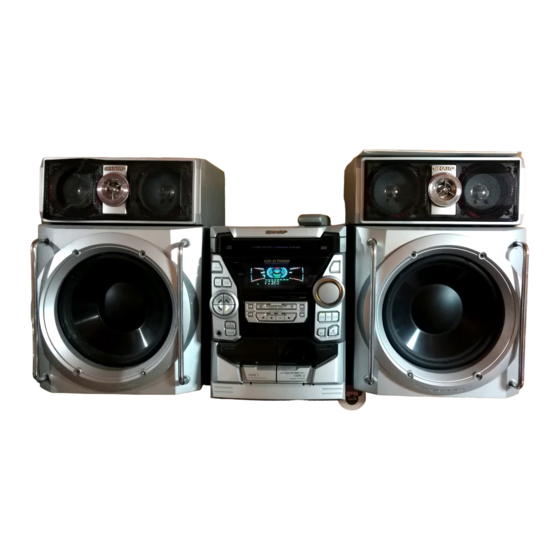
VIDEO CD MINI SYSTEM
CD-K7000V
SPEAKER SYSTEM
CP-C7000
• In the interests of user-safety the set should be restored to its
original condition and only parts identical to those specified be
used.
This document has been published to be used
for after sales service only.
The contents are subject to change without notice.
CD-K7000V,CP-C7000
No. S6051CDK7000V
Page
Advertisement
Table of Contents

Related Manuals for Sharp CD-K7000V


Summary of Contents for Sharp CD-K7000V
-
Page 1: Table Of Contents
CD-K7000V,CP-C7000 SERVICE MANUAL No. S6051CDK7000V VIDEO CD MINI SYSTEM CD-K7000V MODEL SPEAKER SYSTEM CP-C7000 MODEL • In the interests of user-safety the set should be restored to its NTSC/PAL original condition and only parts identical to those specified be used. -
Page 2: Safety Precaution For Service Manual
CD-K7000V,CP-C7000 SAFETY PRECAUTION FOR SERVICE MANUAL WARNINGS THE AEL (ACCESSIBLE EMISSION LEVEL) OF THE LASER POWER OUTPUT IS LESS THAN CLASS 1 BUT THE LASER COMPONENT IS CAPABLE OF EMITTING RADIATION EXCEEDING THE LIMIT FOR CLASS 1. THEREFORE IT IS IMPORTANT THAT THE FOLLOWING PRECAUTIONS ARE OBSERVED DURING SERVICING TO PROTECT YOUR EYES AGAINST EXPOSURE TO THE LASER BEAM. -
Page 3: Specifications
CD-K7000V,CP-C7000 FOR A COMPLETE DESCRIPTION OF THE OPERATION OF THIS UNIT, PLEASE REFER TO THE OPERATION MANUAL. SPECIFICATIONS CD-K7000V General Video CD section Power source: AC 110/127/220/230-240 V, 50/60 Video output format: PAL/PAL 60/NTSC Tuner section Power 210 W consumption: Frequency range: FM;... -
Page 4: Names Of Parts
CD-K7000V,CP-C7000 NAMES OF PARTS CD-K7000V Front panel 28 29 22 23 18 19 20 21 1. Disc Tray 24. (TAPE 2) Record Pause Button 2. (VCD/CD) Karaoke Mode Button 25. (TAPE 2) Reverse Play Button 3. (VCD) Playback Control Button 26. - Page 5 CD-K7000V,CP-C7000 Display 11 12 13 14 15 16 17 18 19 1. Extra Bass Indicator 10. (VCD/CD) More Tracks Indicator 2. Spectrum Analyzer/Volume Level Indicator 11. Sleep Indicator 3. (VCD/CD) Disc Number Indicators 12. FM Stereo Mode Indicator 4. Karaoke Mode Indicator 13.
- Page 6 CD-K7000V,CP-C7000 Remote control 1. Remote Control Transmitter LED 2. Echo Level Up/Down Buttons 3. Karaoke Mode Button 4. Key Control Buttons 5. Vocal Replacer Button 6. (VCD) VCD Auto/On Button 7. (VCD) Playback Control Auto/Off Button 8. (VCD) On Screen Display On/Off Button 9.
-
Page 7: Operation Manual
CD-K7000V,CP-C7000 OPERATION MANUAL – 7 –... - Page 8 CD-K7000V,CP-C7000 – 8 –...
-
Page 9: Disassembly
CD-K7000V,CP-C7000 DISASSEMBLY STEP REMOVAL FIGURE PROCEDURE Caution on Disassembly Follow the below-mentioned notes when disassembling CD Mechanism 1. Hook ....... (R1) x2 11-4 the unit and reassembling it, to keep it safe and ensure 2. Hook ....... (R2) x3 excellent performance: Loading Motor PWB 1. - Page 10 CD-K7000V,CP-C7000 (F1)x3 ø3x10mm (F3)x1 (F1)x2 Lock Lever ø3x6mm (E2)x1 CD Player Unit Headphones (Bottom View) (F2)x3 Power Supply Figure 10-1 Power Amp. (G1)x3 ø3x10mm Push Clamp Lever (F4)x4 Figure 10-4 (H1)x1 CD Player Unit (Top View) Display (H3)x1 Volume Mechanism...
- Page 11 CD-K7000V,CP-C7000 (Q1)x1 (N2)x1 Slide CD Video ø3x8mm Chassis (Q3)x2 Turntable (Q2)x2 Slide Chassis (N1)x2 (Q3)x2 Figure 11-3 (R2)x3 Mechanism CD Player Unit Loading Figure 11-1 Motor (P1)x3 (R1)x1 (R1)x1 (S1)x5 (P1)x3 Figure 11-2 Figure 11-4 CP-C7000 Caution: STEP REMOVAL PROCEDURE...
-
Page 12: Removing And Reinstalling The Main Parts
CD-K7000V,CP-C7000 Screwdriver Range (C1)x4 ø4x16mm (B2)x4 (B1)x1 ø4x16mm Tweeter Super (D1)x2 Tweeter ø3x10mm Driver should be pried away from speaker box. Front Panel Figure 12-1 Figure 12-2 REMOVING AND REINSTALLING THE MAIN PARTS TAPE MECHANISM SECTION TAPE 2 Perform steps 1 to 7 and 11 of the disassembly method to remove the tape mechanism. - Page 13 CD-K7000V,CP-C7000 How to remove the belt (TAPE 2) (See Fig. 13-1) 1. Remove the main belt (D1) x 1 pc., from the motor side. 2. Remove the FF/REW belt (D2) x 1 pc. How to remove the belt (TAPE 1) (See Fig. 13-1) 1.
-
Page 14: Adjustment
CD-K7000V,CP-C7000 ADJUSTMENT • Tape Speed MECHANISM SECTION • Driving Force Check Specified Adjusting Instrument Test Tape Value Point Connection Torque Meter Specified Value 3,000 ± 30 Hz Speaker Normal MTT-111 Variable Play: TW-2111 Tape 1: Over 80 g speed Resistor in... - Page 15 CD-K7000V,CP-C7000 CD SECTION TEST MODE · Setting the test mode • Adjustment Any one of test mode can be set by pressing several keys as Since this CD system incorporates the following automatic follows. adjustment functions, readjustment is not needed when <X-BASS>...
-
Page 16: Notes On Schematic Diagram
CD-K7000V,CP-C7000 NOTES ON SCHEMATIC DIAGRAM • The indicated voltage in each section is the one measured • Resistor: by Digital Multimeter between such a section and the chas- To differentiate the units of resistors, such symbol as K and sis with no signal given. -
Page 17: Block Diagram
CD-K7000V,CP-C7000 27MHz 4.19MHz 21 27 35 45 DQ15 MD11 DQ12 MD12 DQ11 MD15 ICV2 D61012GC ICV1 MPEG DECODER MPEG CONTROLLER IX0352AW MCAS MRAS 35 32 33 95 97 98 99 CNPV3 JK671 VIDEO PICKUP IN UP/DOWN CNS4 CNP4 MOTOR 29 22 21 14... - Page 18 CD-K7000V,CP-C7000 ANTENNA FM IF T302 CF303 IC301 Q715 BF301 TA7358AP Q716 B.P.F FM FRONT END CF351 X351 456kHz CF352 T351 AM IF AM LOOP AM MIX AM IF ANTENNA MO/ST FM RF L312 T301 IC303 FM OSC LA1832S FM IF DET./FM MPX./AM IF...
- Page 19 CD-K7000V,CP-C7000 CNP601 FROM MIC SECTION CNSK1 FL701 M701 VOLUME DISPLAY MOTOR 56 57 58 Q715 Q713 Q716 Q714 JOG701 Q701-Q703 Q710-Q712 RX701 REMOCON SENSOR 58 57 56 55 54 53 52 51 50 49 48 47 46 44 43 42 41 40 VLOAD SYS.
- Page 20 CD-K7000V,CP-C7000 TO MAIN SECTION (TO IC601) CNSK1 10 11 10 11 BIK1 ICK2 M65847AFP1 KEY CONTROL 42 41 40 32 31 VRK1 MIC1 VRK2 VOLUME MIC2 VOLUME PINK1 CHASSIS MIC1 MIC2 Figure 20 BLOCK DIAGRAM (4/4) – 20 –...
-
Page 21: Schematic Diagram / Wiring Side Of P.w.board
CD-K7000V,CP-C7000 P27 12 - F TO MAIN PWB CNP601 2 3 4 5 7 8 9 CNSK1 2 3 4 5 7 8 9 BIK1 KARAOKE PWB-D MIC SIGNAL RK36 CK69 2.2/50 RK47 RK35 RK38 RK34 RK48 CK44 47/25 12 13 14... - Page 22 CD-K7000V,CP-C7000 KTA1298 Y KDS193 RV84 4.7K KTA1298 Y RV85 47/6.3 3.3V KRC104 S KDS193 C2PO LRCK BCLK DATAD MBUSY AV_GND D_GND MCLK RV86 4.7K CV11 0.22 9 8 7 6 5 4 3 2 16 15 14 13 12 11 10...
- Page 23 CD-K7000V,CP-C7000 CD VIDEO PWB-C(1/2) VIDEO SIGNAL RV64 RV95 CV39 RV62 6.8K 1000/6.3 ICV4 RV63 NJM2267M VIDEO OPERATION AMP. CV40 22/6.3 CV41 4.7/25 P27 10 - A RV96 CV17 0.01 CNS606 CV18 1000/6.3 TO MAIN PWB CV15 RV61 4.7/25 100K RV60 CV11 0.22...
- Page 24 CD-K7000V,CP-C7000 CD VIDEO PWB-C(2/2) CD SIGNAL SERVO CONT Vref TIN1 FIN1 0.047 FIN2 PDO1 TIN2 LA9235M 1.5M PDO2 SERVO AMP. 47/6.3 2.2/50 VVSS FIN1 CNP1 0.022 0.022 ODRV PCKIST RFSW FIN2 100P VVDD 120K AGCON 1.2K TIN1 RF– (CH) SLCIST...
- Page 25 CD-K7000V,CP-C7000 C71 100P C72 0.01 C73 100P C74 100P KTA1504 GR C75 100P SERVO DSP C76 100P C77 100P CONTROL C78 100P 2.2µH EFMO VDD5V 0.047 0.022 PDO1 COMMAND GENERAL INTERFACE 1.5M SBCK PDO2 100/6.3 2.2/50 VVSS SUBCODE FRAME SYNC...
- Page 26 CD-K7000V,CP-C7000 C408 C412 C406 R404 0.0047 10/50 22P(CH) R408 R412 R410 R406 C410 4.7K C402 2.2K 4.7K 2.2/50 47/25 IC401 C604 KIA4558P 0.022 OPE AMP. C606 100/16 C602 22/50 VREF C405 R409 R405 R401 R608 C614 4.7K 100K C608 10/50...
- Page 27 CD-K7000V,CP-C7000 CNPV3 P23 11 - C CNS606 TO CD VIDEO PWB BI606 SUR_ON/OFF MAIN PWB-A1(1/ 2) JK671 PLAYBACK SIGNAL CD SIGNAL VIDEO RECORD SIGNAL VIDEO SIGNAL FM SIGNAL MIC SIGNAL C602 22/50 R608 C614 C637 C608 10/50 C601 0.001 0.022 R606 3.9K...
- Page 28 CD-K7000V,CP-C7000 AM TRACKING fL T303 C331 0.047 C330 C323 0.022 C338 0.001 AM ANT. C332 D301 0.022 1SS133 D302 1SS133 VD301 R358 AM OSC. SVC348S 3.9K C335 C301 560P T306 0.001 D303 1SS133 D304 C334 1SS133 R323 AM LOOP AM BAND...
- Page 29 CD-K7000V,CP-C7000 FM SIGNAL AM SIGNAL C371 R361 1/50 1.2K R350 R358 2.7K 3.9K R362 C372 1.2K 1/50 C367 1/50 IC303 LA1832S FM IF DET./FM MPX./AM IF C358 1/50 R355 C357 3.3K 2.2/50 T351 C356 0.001 AM IF SPARE L352 100µH ZD351 MTZJ5.1B...
- Page 30 CD-K7000V,CP-C7000 DISPLAY PWB-A2 R713 R714 100K 100K R715 FL701 100K 52 51 42 41 32 31 29 20 RS723 RS724 R701 R704 R716 100K 100K 100K R719 C709 C715 82 83 84 85 87 88 89 92 93 94 95...
- Page 31 CD-K7000V,CP-C7000 P25 12 - E TO CD SERVO PWB CNP12 2 3 4 5 7 8 9 11 12 CNS703 2 3 4 5 7 8 9 10 11 12 BI703 R718 C722 C738 47/50 220/10 R883 R885 R884 C725...
- Page 32 CD-K7000V,CP-C7000 IC901 STK4115G POWER AMP. R901 C913 C911 Q903 220P D909 KTC3199G 1SS133 R903 R917 R905 D904 D903 0.1(3W) 1SS133 1SS133 C912 C923 R919 220P 0.022(ML) 1.5K Q901 KTC3199GR R921 D907 R911 1.8K 1SS133 R904 Q902 KTC3199GR C914 R909 D908...
- Page 33 CD-K7000V,CP-C7000 POWER AMP. PWB-B2 R945 R947 FM SIGNAL 3.9(1/2W) 5.6(1/2W) C931 C935 0.022 0.022 (ML) (ML) SO901 C933 C937 SPEAKER RL901 0.022 0.022 L901 TERMINAL (ML) (ML) 0.29µH L CH L904 Q903 D909 R925 0.29µH KTC3199GR 1SS133 10(1/2W) SPEAKER C927 0.22...
- Page 34 CD-K7000V,CP-C7000 P39 10 - E TO KARAOKE CNSK1 MAIN PWB-A1 R378 R373 X352 R372 R388 R374 R359 C382 1 2 3 4 5 6 7 8 9 10 11 R376 C395 C381 IC302 C387 R360 R379 22 21 20 19 18 17 16 15 14 13 12...
- Page 35 CD-K7000V,CP-C7000 P37 10 - H TO DISPLAY PWB CNS701 CNS11 P40 3 - A FFC701 CNP11 TO CD VIDEO R129 1 3 5 7 9 11 13 15 17 19 21 23 25 27 29 Q129 2 4 6 8 10 12 14 16 18 20 22 24 26 28 30...
- Page 36 CD-K7000V,CP-C7000 DISPLAY PWB-A2 Q703 FL701 E C B R719 R716 R705 R704 E C B Q702 R702 R701 E C B RS723 Q701 RS724 Q712 E C B SW714 RS725 DIMMER Q711 E C B Q710 E C B IC701...
- Page 37 CD-K7000V,CP-C7000 P40 5 - A TO CD VIDEO PWB CNP12 CNS703 BI703 R725 FL701 R726 LED722 C727 R799 IC704 C732 C731 C728 C730 D716 D718 R798 Q709 RX701 R796 D720 R797 C733 R744 R777 R709 RD02 C729 D717 RD01 R707...
- Page 38 CD-K7000V,CP-C7000 P35 7 - H TO MAIN PWB POWER AMP. PWB-B2 CNS901 Q904 L903 R923 1 2 3 4 5 6 7 8 9 10 11 12 13 1415 1617 18 R942 Q903 L901 CNP901 R929 C927 R941 D909 C930...
- Page 39 CD-K7000V,CP-C7000 VRK1 VRK2 MIC 1 MIC 2 VOLUME MIC 1 VOLUME MIC 2 D913 R950 C946 LG901 R909 PINK1 R907 CK17 R908 WT601 R910 ICK1 (286) C814 C813 CK23 TO CHASSIS R803 RK28 RK12 RK35 ZD802 ZDK1 RK36 JK670 CK43...
- Page 40 CD-K7000V,CP-C7000 CD VIDEO PWB-C (BOTTOM VIEW) P35 10 - A P37 10 - A P34 2 - H TO MAIN PWB TO DISPLAY PWB TO MAIN PWB CNS606 CNS703 CNS11 CNP12 CNP11 CNPV3 121110 9 ZD61 48 49 RV84 ICV1...
- Page 41 CD-K7000V,CP-C7000 CD VIDEO PWB-C (TOP VIEW) RV64 RV63 CV17 RV62 ICV4 CV39 RV96 RV95 CV41 CV18 RV61 COLOR TABLE BROWN CV22 CV11 R D ( R ) 80 85 90 95 ORANGE YELLOW CV26 ICV2 RV38 GREEN BLUE RV37 VIOLET...
- Page 42 CD-K7000V,CP-C7000 TAPE MECHANISM ASSEMBLY P36 2 - H TO DISPLAY PWB CNS702 FFC702 TAPE MECHANISM PWB-E SOLENOID SOLENOID TAPE MOTOR TAPE 2 TAPE 1 RECORD/PLAYBACK/ERASE HEAD PLAYBACK HEAD COLOR TABLE BROWN RD(R) ORANGE YELLOW GREEN BLUE VIOLET GRAY 6 5 4 3 2 1...
-
Page 43: Voltage
CD-K7000V,CP-C7000 VOLTAGE IC101 IC303 IC701 ICK1 ICV3 ICV2 PIN VOLTAGE PIN VOLTAGE NO. VOLTAGE NO. VOLTAGE NO. VOLTAGE NO. VOLTAGE VOLTAGE NO. VOLTAGE NO. VOLTAGE VOLTAGE 1.6V 0.7V 0V (0V) 2.1V (2.1V) 4.6V 4.9V 3.0V 3.3V 3.3V 1.6V 0V (0V) 4.5V (4.8V) -
Page 44: Waveforms Of Cd Circuit
CD-K7000V,CP-C7000 WAVEFORMS OF CD CIRCUIT Stopped Stopped 1999/04/05 17:33:17 CH1=500mV CH3=500mV 500ms/div CH1=500mV CH3=1V CH4=1V 500ms/div DC 10:1 DC 10:1 (500ms/div) DC 10:1 DC 10:1 DC 10:1 (500ms/div) NORM:20kS/s NORM:20kS/s PDO1 IC2 1 IC2 24 PDO2 IC2 2 IC2 23... -
Page 45: Troubleshooting
CD-K7000V,CP-C7000 TROUBLE SHOOTING When the CD does not function When the CD section does not operate when the objective lens of the optical pickup is dirty, this section may not operate. Clean the objective lens, and check the playback operation. When this section does not operate even after the above step is taken, check the following items. - Page 46 CD-K7000V,CP-C7000 (1) Focus-HF system check Stopped CH1=500mV CH3=500mV 500ms/div Although a CD is inserted and the cover is closed, "NO DC 10:1 DC 10:1 (500ms/div) NORM:20kS/s DISC" is displayed. Press the OPEN/CLOSE switch (SW1) without inserting a disc, and try starting the playback operation.
- Page 47 CD-K7000V,CP-C7000 (2) Tracking system check Check the TE waveform at pin 18 on IC1. The tracking servo is not activated. If the waveform shown in Figure 47-1 appears and soon after Check the peripheral circuits at pins 18 and 19 on IC1, pin 23 on NO DISC appears.
- Page 48 CD-K7000V,CP-C7000 (4) PLL system check Stopped 1999/04/05 17:33:17 CH1=500mV CH3=1V CH4=1V 500ms/div DC 10:1 DC 10:1 DC 10:1 (500ms/div) NORM:20kS/s When a disc is loaded, start play operation. PDO1 The HF waveform is normal, but the TOC data cannot be PDO2 read.
-
Page 49: Function Table Of Ic
CD-K7000V,CP-C7000 FUNCTION TABLE OF IC IC1 VHiLA9235M/-1: Servo Amp. (LA9235M) ODRV FIN1 LA9235M RFSW FIN2 AGCON 28 RF- FIN3 FIN4 26 N/C 25 PH 24 BH REF1 ODRV 23 N/C PH/BH 22 RFEV VREF 21 FE- 20 FE LDOF 19 TE-... - Page 50 CD-K7000V,CP-C7000 IC2 VHiLC78636E-1: Servo DSP (LC78636E) (1/2) Terminal Name Input/Output Setting in Reset Function Pin No. PDO1 Output – For PULL Phase-comparison output terminal for built-in VCO control. PDO2 Output – Phase-comparison output terminal for built-in VCO control. Rough servo : OFF, phase servo : ON.
- Page 51 CD-K7000V,CP-C7000 IC2 VHiLC78636E-1: Servo DSP (LC78636E) (2/2) Terminal Name Input/Output Setting in Reset Function Pin No. LVDD – – L channel Power terminal for L channel. LCHO Output 1/2VDD D/A converter L channel output terminal. LVSS – – Ground terminal for L channel. Surely connected to 0V.
- Page 52 CD-K7000V,CP-C7000 IC701 RH-iX0360AWZZ: System Microcomputer (IX0360AW) (1/2) Pin No. Port Name Terminal Name Input/Output Function — (+) POWER SUPPLY -20dBATT Output -20dB ATTENUATOR S-BUSY Output Not used LCK 1 Output LED DRIVER LCK (BU2092-2) LCK 0 Output LED DRIVER LCK (BU2092-1)
- Page 53 CD-K7000V,CP-C7000 IC701 RH-iX0360AWZZ: System Microcomputer (IX0360AW) (2/2) Pin No. Port Name Terminal Name Input/Output Function P120 T2 PLAY SW_B Input PLAY SWITCH FOR T2 P119 FPA(F-REC) Input TAPE 2 A-SIDE FULL PROOF P118 FPB(R-REC) Input TAPE 2 B-SIDE FULL PROOF...
- Page 54 CD-K7000V,CP-C7000 IC601 VHiLC75341/-1: Audio Processor (LC75341) LOUT ROUT LBASS RBASS LTRE RTRE LSEL0 RSEL0 R1 R2 24 23 22 21 20 19 18 17 16 15 14 13 LC75341 10 11 12 Figure 54 BLOCK DIAGRAM OF IC – 54 –...
- Page 55 CD-K7000V,CP-C7000 ICK1 VHiM65856SP-1: Mic Amp. (M65856SP) (1/2) Pin No. Port Name Input/Output Function MICSW Input Microphone SW L: MIC OFF, H: MIC ON MCLKCONT — Clock Control Controls built-in clock generation circuit with external R VALC — ALC operating voltage setting terminal...
- Page 56 CD-K7000V,CP-C7000 ICK1 VHiM65856SP-1: Mic Amp. (M65856SP) (2/2) Pin No. Port Name Input/Output Function KEYCONIN Input Monaural input for external KEY CONTROL IC Input/Output interface terminal for external KEY CONTROL IC SOURCEOUT Output Monaural input for external KEY CONTROL IC Input/Output interface terminal for external KEY CONTROL IC...
- Page 57 CD-K7000V,CP-C7000 ICK2 VHiM65847AFP1: Key Control (M65847AFP) Function Terminal Pin No. Port Name Input/Output Name Self mode Easy mode MCU mode ADCONT A/D control — Determines adaptive time constant for A/D conversion by ADM system DACONT1 D/A 1 control — Determines adaptive time constant for D/A conversion by ADM system...
- Page 58 CD-K7000V,CP-C7000 ICK2 VHiM65847AFP1: Key Control (M65847AFP) A D C O N T M O D E 2 D A C O N T1 M O D E 1 D A C O N T2 D A I N T O U T...
- Page 59 CD-K7000V,CP-C7000 ICV1 RH-iX0352AWZZ: MPEG Controller (IX0352AW) Pin No. Port Name Terminal Name Function Input/Output VOCAL CANCEL Output Vocal cancel K_C_DATA Output Key control IC data K_C_CLK Output Key control IC clock K_C_STRB Output Key control IC strobe KEY CONT. Output...
- Page 60 CD-K7000V,CP-C7000 ICV2 VHiD61012GC-1: MPEG Decoder (D61012GC) (1/2) Pin No. Terminal Name Input/Output Function — Digital supply. HD7-HD4 Input/Output Host data bus. HD7 = MSB, HDO = LSB. Internally pulled down. Pull down resistance = approx. 42 kohms. Can quit this pull down with the HD_PD_OFF register (74H, bo).
- Page 61 CD-K7000V,CP-C7000 ICV2 VHiD61012GC-1: MPEG Decoder (D61012GC) (2/2) Pin No. Terminal Name Input/Output Function Output DRAM write enable signal. MCAS Output DRAM column address strobe signal. 54-56 MD7-MD5 Input/Output DRAM data bus. MD15 = MSB, MD0 = LSB. Internally pulled down. Pull down resistance is approx. 42 kohms.
- Page 62 CD-K7000V,CP-C7000 ICV3 VHiSDM4260C-1: DRAM (SDM4260C) Function Port Name Pin No. Power supply 2-10 DQ0-DQ7 Data input/output 11*,12* Not used Read/write enable Row address strobe Not used 16-19 A0-A3 Address input (row/refresh: A0 to A3) (Column: A0 to A3) Power supply...
- Page 63 CD-K7000V,CP-C7000 ICV4 VHiNJM2267M-1: Video operation amp. (NJM2267M) Function Terminal Name Pin No. Clamp input terminal Input of 1.9 V clamp, 1 Vp-p composite or Y-signal Ground Sag correction terminal Able to obtain an output without any sag by feeding back the sag, generated from output coupling C, using the external C (see block diagram).
-
Page 64: Fl Display
CD-K7000V,CP-C7000 FL701 VVKBJ744GNK-1: FL Display (1G~8G) PIN CONNECTION PIN NO. 20 19 18 17 16 15 14 13 12 11 10 CONNECTION 9G 8G 7G 6G 5G 4G 3G 2G NP NP F1 F1 F1 30 29 28 27 26 25 24 23 22 21 PIN NO. - Page 65 “HOW TO ORDER REPLACEMENT PARTS” To have your order filled promptly and correctly, please furnish the For U.S.A. only following information. Contact your nearest SHARP Parts Distributor to order. 1. MODEL NUMBER 2. REF. No. 3. PART NO. 4. DESCRIPTION For location of SHARP Parts Distributor, Please call Toll-Free;...
- Page 66 CD-K7000V,CP-C7000 PRICE PRICE DESCRIPTION PARTS CODE PARTS CODE DESCRIPTION RANK RANK D301~305 VHD1SS133//-1 AA Silicon,1SS133 CD-K7000V D401 VHD1SS133//-1 AA Silicon,1SS133 D561~566 VHD1SS133//-1 AA Silicon,1SS133 INTEGRATED CIRCUITS D601,602 VHD1SS133//-1 AA Silicon,1SS133 D705 VHD1SS133//-1 AA Silicon,1SS133 VHILA9235M/-1 AQ Servo Amp.,LA9235M D707 VHD1SS133//-1...
- Page 67 CD-K7000V,CP-C7000 PRICE PRICE PARTS CODE DESCRIPTION PARTS CODE DESCRIPTION RANK RANK RCRM-0201AFZZ AD Ceramic,4.19 MHz C313 VCCCMN1HH220J J AA 22 pF (CH),50V AA 0.0047 µF,16V RCRSP0013AWZZ J AG Crystal,27 MHz C314,315 VCTYMN1CX472K J AA 0.022 µF,25V C316 VCTYMN1EF223Z CAPACITORS AA 0.001 µF,50V...
- Page 68 CD-K7000V,CP-C7000 PRICE PRICE PARTS CODE DESCRIPTION PARTS CODE DESCRIPTION RANK RANK AA 0.001 µF,50V AA 0.022 µF,50V C637 VCKYPA1HB102K CK19 VCKZPA1HF223Z AA 0.0033 µF,50V,Mylar AC 0.22 µF,50V,Thin Film C641,642 VCQYKA1HM332K J CK20 VCFYHA1HA224J AB 47 µF,50V,Electrolytic AB 0.068 µF,50V,Mylar C709...
- Page 69 CD-K7000V,CP-C7000 PRICE PRICE PARTS CODE DESCRIPTION PARTS CODE DESCRIPTION RANK RANK VRS-TV2AB470J AA 47 ohms,1/10W R383 VRD-MN2BD562J AA 5.6 kohms,1/8W R51~56 VRS-TV2AB683J AA 68 kohms,1/10W R384 VRD-ST2CD562J AA 5.6 kohms,1/6W VRS-TV2AB221J AA 220 ohms,1/10W R385 VRD-MN2BD562J AA 5.6 kohms,1/8W R67,68...
- Page 70 CD-K7000V,CP-C7000 PRICE PRICE DESCRIPTION PARTS CODE PARTS CODE DESCRIPTION RANK RANK R740,741 VRD-ST2CD102J AA 1 kohm,1/6W R945,946 VRD-RT2HD3R9J AA 3.9 ohms,1/2W R742~744 VRD-MN2BD102J AA 1 kohm,1/8W R947,948 VRD-RT2HD5R6J AA 5.6 ohms,1/2W R746 VRD-MN2BD103J AA 10 kohm,1/8W R949 VRD-ST2CD474J AA 470 kohms,1/6W...
- Page 71 CD-K7000V,CP-C7000 PRICE PRICE PARTS CODE DESCRIPTION PARTS CODE DESCRIPTION RANK RANK RV59 VRS-TV2AB103J AA 10 kohm,1/10W QSW-F9001AW01 AD Switch,Leaf Type [Pickup In] RV60 VRS-TV2AB101J AA 100 ohm,1/10W SW601 QSW-S0024AWZZ J AE Switch,Slide Type RV61 VRS-TV2AB104J AA 100 kohm,1/10W [SPAN SELECTOR]...
- Page 72 CD-K7000V,CP-C7000 PRICE PRICE PARTS CODE DESCRIPTION PARTS CODE DESCRIPTION RANK RANK 201-13 JKNBZ0740AWSA Knob,Function,A 92LPT0309506 AD Gear,Turntable Drive 201-14 JKNBZ0673AWSA AF Knob,Function,B 92LPT0309507 AD Gear,Open/Close Drive 201-15 JKNBZ0660AWSA AF Knob,Tuning 92LPT0309508 AD Gear,Planet 201-16 JKNBZ0661AWSA AE Knob,Dimmer 92LPT0309509 AD Gear,Drive...
- Page 73 Operation Manual [For Thailand] 92L3191C700010 Speaker Cord Ass’y TINSZ0600AWZZ Operation Manual 92L6051C700000 Label,Bar Code [Except for Thailand] 92L70032000310 AD Polyethylene Bag,Tweeter TLABB0001AWZZ AB Label,SHARP Corporation Japan 92L70032002600 Polyethylene Bag,Woofer for Set 92L71525005600 Sheet,Miramat,Woofer TLABE0449AWZZ Label,Bar Code 92L71525005700 Sheet,Miramat,Tweeter TLABE0450AWZZ Label,Bar Code 92L720BC700000 Packing Add.,Bottom,Woofer...
- Page 74 CD-K7000V,CP-C7000 CD-K7000V 306-2 306-1 306-3 703x2 305x2 PWB-F Figure 9 CD MECHANISM EXPLODED VIEW – 9 –...
- Page 75 CD-K7000V,CP-C7000 CD-K7000V BELT CONNECTION FF/REW FF/REW ROLLER ROLLER 202-1 ASS'Y 614x2 ASS'Y PWB-A1 FLYWHEEL FLYWHEEL ASS'Y ASS'Y MAIN BELT 610x10 TAPE1 TAPE2 610x2 PWB-E2 610x2 608x3 Q852 202-2 Q851 605x11 Q850 Silicon M701 PWB-A2 Grease 624x2 M901 PWB-E1 619x2 291x2...
- Page 76 CD-K7000V,CP-C7000 CD-K7000V 604x2 604x2 MECHANISM PWB-H 250x4 239x4 204-2 204-1 PWB-C 204-3 Figure 11 CABINET EXPLODED VIEW (2/2) – 11 –...
- Page 77 CD-K7000V,CP-C7000 CP-C7000 CROSSOVER NETWORK SP1,2 WOOFER SP1,2 919x8 920x4 912x2 918x4 911x4 918x4 912x2 SP1,2 WOOFER CROSSOVER NETWORK Figure 12 SPEAKER EXPLODED VIEW (1/2) – 12 –...
- Page 78 CD-K7000V,CP-C7000 CP-C7000 SP7,8 Super Tweeter C3,4 C1,2 Capacitor Capacitor 922x2 SP5,6 SP3,4 Mid Range Tweeter SP5,6 921x4 923x2 SP7,8 C1,2 Capacitor 918x2 921x4 C3,4 Capacitor 912x4 SP3,4 SUPER TWEETER SP7(L-CH) SP8(R-CH) TWEETER SP5(L-CH) SP6(R-CH) C1,2 3.3µF/100V C3,4 6.8µF/100V MID RANGE...
- Page 79 CD-K7000V,CP-C7000 — M E M O — – 14 –...
- Page 80 CD-K7000V,CP-C7000 © COPYRIGHT 2000 BY SHARP CORPORATION ALL RIGHTS RESERVED. No part of this publication may be reproduced, stored in a retrieval system, or transmitted in any from or by any means, electronic, mechanical, photocopying, recording, or otherwise, without prior written permission of the publisher.
Need help?
Do you have a question about the CD-K7000V and is the answer not in the manual?
Questions and answers