
Related Manuals for SMH Technologies FlashRunner LAN 2.0


Summary of Contents for SMH Technologies FlashRunner LAN 2.0
- Page 1 FlashRunner LAN 2.0 Next Generation High-Performance, Compact Standalone In-System Programmer User’s Manual Revision 0.5 — Apr 2021 Copyright © 2018 SMH Technologies DC11261...
- Page 2 SMH Technologies reserves the right to make improvements to FlashRunner, its documentation and software routines, without notice. Information in this manual is intended to be accurate and reliable. However, SMH Technologies assumes no responsibility for its use; nor for any infringements of rights of third parties which may result from its use.
-
Page 3: Table Of Contents
Contents BEFORE STARTING ......................5 .................... 5 MPORTANT OTICE TO SERS ........................... 5 AFETY .................... 7 ETTING ECHNICAL UPPORT ................... 7 DDITIONAL OCUMENTATION OVERVIEW ........................8 LAN 2.0 N ? ............8 HAT IS LASH UNNER ENERATION 2.1.1 General features ....................10 2.1.2 Hardware features ..................... - Page 4 NVIRONMENTAL PECIFICATIONS Index of Figures Figure 1: FlashRunner LAN 2.0 Next Generation in closed case version ......9 Figure 2: Power jack, ATE control connector, USB and LAN ........13 Figure 3: “ISP” DIN connectors group ................. 14 Figure 4: FlashRunner LAN 2.0 Next Generation Top Panel ........15 Figure 5: DIN41612 mating pin assignment example ..........
-
Page 5: Before Starting
While every effort has been made to ensure the accuracy of all information in this document, SMH Technologies assumes no liability to any party for any loss or damage caused by errors or omissions or by statements of any kind in this document, its updates, supplements, or special editions, whether such errors are omissions or statements resulting from negligence, accidents, or any other cause. - Page 6 To protect FlashRunner LAN 2.0 Next Generation against electrostatic discharge (ESD), always connect yourself to the ground (e.g. via wrist straps) when handling the instrument. Always store FlashRunner LAN 2.0 Next Generation inside an antistatic bag when not in use. Disclaimer: when integrating FlashRunner LAN 2.0 Next Generation please pay attention to place it in a well-ventilated area in order to avoid overheating related damages.
-
Page 7: Getting Technical Support
Technologies offers fast and knowledgeable technical support to all of its customers and is always available to solve specific problems or meet specific needs. To get in touch with SMH Technologies, please refer to the contact information below. Phone: +39 0434 421111... -
Page 8: Overview
2 Overview 2.1 What is FlashRunner LAN 2.0 Next Generation? FlashRunner LAN 2.0 Next Generation is a compact high-integration in-system gang programmer, based on the new and innovative FlashRunner 2.0 cutting-edge technology. FlashRunner LAN 2.0 Next Generation is designed for programming multi- PCB panel assemblies, with microcontroller, eMMC and NAND memories. -
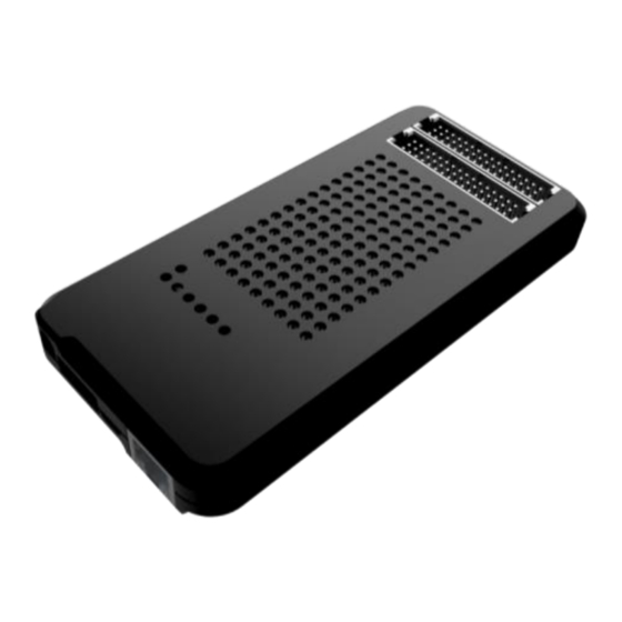
Page 9: Figure 1: Flashrunner Lan 2.0 Next Generation In Closed Case Version
FlashRunner LAN 2.0 Next Generation is composed of a carrier board that hosts up to 4 programming channels. The engine board on top of it is a System on Module enclosing FlashRunner 2.0 core technology in a compact and easy to integrate format. -
Page 10: General Features
2.1.1 General features ▪ Fastest programming algorithms (as fast as target device’s memory technology limit), approved by silicon manufacturers; ▪ Up to 4 parallel and independent channels ▪ Easy ATE integration; ▪ Standalone operations ▪ Controllable by ATE through optoisolated LAN and USB, or parallel control lines; ▪... -
Page 11: Package Checklist
▪ Erase, blank check, program, read, verify, oscillator trimming, etc. 2.2 Package Checklist FlashRunner LAN 2.0 Next Generation comes in packaging variants: Open-Frame and Closed-Case. The relative packages include the following items: Table 1: FlashRunner 2.0 NXG Open Frame Package Checklist Qty. - Page 12 Table 2: FlashRunner 2.0 NXG Closed Case Package Checklist Qty. Description FlashRunner LAN 2.0 Next Generation Closed Case Unit Control Interface Flat Cable 15cm ISP Flat Cable Extension 30cm Ethernet cross cable 2 meter RJ45 Micro USB2 cable 1.8 meter...
-
Page 13: Hardware Overview
2.3 Hardware Overview 2.3.1 Power Supply FlashRunner LAN 2.0 Next Generation is powered through a 15V power supply connected to a DC plug connector. 2.3.2 ATE Control Connector ATE Control DIN Connectors are used by an ATE system to control FlashRunner LAN 2.0 Next Generation instead of communicating with the instrument through the USB or... -
Page 14: Lan Connector
LAN Connector LAN Connector is used to communicate with Host PC system. Use provided cross cable to connect FlashRunner LAN 2.0 Next Generation with your PC. For more information check chapter 2.3.3 and check related documentation on FlashRunner 2.0 Programmer's Manual to correctly set up your host PC system 2.3.4... -
Page 15: Leds
DAC and ADC for the measurement of VPROG currents and voltages has been successful. If the test passes, the STATUS_LED stays on. If the test fails, the STATUS_LED blinks. If the STATUS_LED remains off there is something wrong. Figure 4: FlashRunner LAN 2.0 Next Generation Top Panel... -
Page 16: Programming Drivers And Licenses
You can purchase additional licenses at any future moment. Programming drivers and license files are stored inside FlashRunner LAN 2.0 Next Generation storage memory (see the FlashRunner 2.0 Programmer’s Manual for more information). -
Page 17: Channel Upgrade Licenses
FR2.0A16, you could purchase a Channel Upgrade License. Please ask our Sales Team (sales@smh-tech.com). 2.6 Upgrading the Firmware FlashRunner LAN 2.0 Next Generation firmware can be easily upgraded using the FlashRunner 2.0 WorkBench software. For more information, please refer to the FlashRunner 2.0 Programmer’s Manual. -
Page 18: System Setup
This chapter will explain how to set up FlashRunner LAN 2.0 Next Generation for the first time. The new FR2.0 WorkBench project Wizard allows an easy and fast system setup. -
Page 19: Interfacing With Your Test/Programming Equipment
▪ Interface FlashRunner LAN 2.0 Next Generation with your test/programming equipment; ▪ Connect FlashRunner LAN 2.0 Next Generation to host PC system (if you use it in Host Mode); ▪ Power up FlashRunner LAN 2.0 Next Generation; ▪ Set up LAN settings (if you use the Ethernet connection);... -
Page 20: Connectors
4 Connectors 4.1 Overview FlashRunner LAN 2.0 Next Generation connects to your programming/testing system through: ▪ “ISP” connectors: 48 way, 3 rows, DIN 41612, pitch = 2.54mm (male) ▪ “ATE CONTROL” connector: 14 way, 2 rows, pitch = 1.27mm (male) ▪... -
Page 21: Figure 5: Din41612 Mating Pin Assignment Example
Note on DIN41612 connectors: The use of these connectors implies that the pin assignment of a possible type C/2 female connector will be mirrored over the rows with respect to the pin assignment of the R/2 male onboard. Therefore, pin A1 of the R/2 male will correspond to A16 on the C/2 female, B1 will correspond to B16 and so forth. -
Page 22: Figure 6: Isp Connector
Figure 6: ISP Connector Table 4: ISP Connector Signals (Channels 1 and 2) Pin # Signal Name Description VPROG0_CH2 ISP Channel 2: Programmable voltage 0 VPROG1_GND_CH2 ISP Channel 2: Programmable voltage 1 Ground DIO1_CH2 ISP Channel 2: Digital input/output 1 DIO2_GND_CH2 ISP Channel 2: Digital input/output 2 Ground DIO4_CH2... - Page 23 Pin # Signal Name Description DIO0_CH2 ISP Channel 2: Digital input/output 0 DIO1_GND_CH2 ISP Channel 2: Digital input/output 1 Ground DIO3_CH2 ISP Channel 2: Digital input/output 3 DIO4_GND_CH2 ISP Channel 2: Digital input/output 4 Ground DIO6_CH2 ISP Channel 2: Digital input/output 6 DIO7_GND_CH2 ISP Channel 2: Digital input/output 7 Ground RLY_ON_CH2...
- Page 24 Pin # Signal Name Description PWR_RLY_CH3 ISP Channel 3: Relay Barrier Power Source VPROG0_CH3 ISP Channel 3: Programmable voltage 0 VPROG1_GND_CH3 ISP Channel 3: Programmable voltage 1 Ground DIO1_CH3 ISP Channel 3: Digital input/output 1 DIO2_GND_CH3 ISP Channel 3: Digital input/output 2 Ground DIO4_CH3 ISP Channel 3: Digital input/output 4 DIO5_GND_CH3...
-
Page 25: Ate Control Connector
4.3 ATE Control Connector ATE Control Connector is used to communicate with the host system and for integration with automatic programming/testing equipment (ATE). Note: all control signals are referenced to GND_I, separate from GND. This allows a host system to safely communicate with FlashRunner LAN 2.0 Next Generation even when the target boards have different ground reference compared to the host system’s (and it’s not possible to connect them together). -
Page 26: Usb Connector
You can use the provided expansion board to connect to the control interface’s signals which are indicated on the board’s silkscreen. Figure 8: Control Interface expansion board 4.4 USB Connector The USB-B connector can be used to communicate with the ATE system. Note: USB signals are referenced to GND_USB, separate from GND, and GND_I. -
Page 27: Flashrunner Lan 2.0 Next Generation Tools
It can be upgraded to a 4 channels version according to your needs. Please contact your sales representative for further information. Figure 9: FRLAN2P0NXGRB two channels relay barrier Relay barrier is self-powered when plugged into FlashRunner LAN 2.0 Next Generation. -
Page 28: Figure 10: Relay Barrier Isp Connector Front View
The driving signals for the relays are given by the FlashRunner through the dedicated pins. Figure 10: Relay Barrier ISP connector front view Table 7: Relay Barrier ISP "output" signals Pin # Signal Name Description DIO7_CHA ISP Channel A: Digital input/output 7 DIO5_GND_CHA ISP Channel A: Digital input/output 5 Ground DIO4_CHA... -
Page 29: Figure 11: Frlan2P0Nxgrb Auxiliary Input Connector
Pin # Signal Name Description DIO4_GND_CHB ISP Channel B: Digital input/output 4 Ground DIO3_CHB ISP Channel B: Digital input/output 3 DIO1_GND_CHB ISP Channel B: Digital input/output 1 Ground DIO0_CHB ISP Channel B: Digital input/output 0 VPROG0_GND_CHB ISP Channel B: Programmable voltage 0 Ground Not Connected DIO6_GND_CHA ISP Channel A: Digital input/output 6 Ground... -
Page 30: Figure 12: Relay Barrier Application Note
Block diagram of the ISP lines switching capabilities: Figure 12: Relay Barrier Application Note Table 8: Auxiliary Connector Pinout Pin # Signal Name Description AUX_A_DIO0 ISP Channel A: Digital input/output 0 AUX_B_VPROG0 ISP Channel B: Digital input/output Vprog0 AUX_A_DIO1 ISP Channel A: Digital input/output 1 AUX_B_VPROG1 ISP Channel B: Digital input/output VProg1 AUX_A_DIO2... -
Page 31: Figure 13: Auxiliary Interface Expansion Board For Relay Barrier
Pin # Signal Name Description AUX_A_GND0 ISP Channel A: Digital input/output Ground 0 AUX_B_DIO6 ISP Channel B: Digital input/output 6 AUX_A_GND1 ISP Channel A: Digital input/output Ground 1 AUX_B_DIO7 ISP Channel B: Digital input/output 7 AUX_A_GND2 ISP Channel A: Digital input/output Ground 2 AUX_B_GND2 ISP Channel B: Digital input/output Ground 2 Figure 13: Auxiliary interface expansion board for relay barrier... -
Page 32: Cable Interface
5.2 Cable Interface A cable interface is available for the FlashRunner LAN2P0 NXG to connect the targets using our special twisted cables, keeping good signals integrity. Each header connector (H1..H4) is the output of one programming channel and can be connected to a FRHDRPSTR through a FRCABLE. Figure 14: Auxiliary interface expansion board for relay barrier Parameter Value... - Page 33 Table 9: Header Connector Signals Channel 1 Pin # Signal Name Description H1-1 DIO0_CH1 ISP Channel 1: Digital input/output 0 H1-2 DIO0_GND_CH1 ISP Channel 1: Digital input/output 0 Ground H1-3 DIO1_CH1 ISP Channel 1: Digital input/output 1 H1-4 DIO1_GND_CH1 ISP Channel 1: Digital input/output 1 Ground H1-5 DIO2_CH1 ISP Channel 1: Digital input/output 2...
- Page 34 Pin # Signal Name Description H2-19 VPROG1_CH2 ISP Channel 2: Programmable voltage 1 H2-20 VPROG1_GND_CH2 ISP Channel 2: Programmable voltage 1 Ground Table 11: Header Connector Signals Channel 3 Pin # Signal Name Description H3-1 DIO0_CH3 ISP Channel 3: Digital input/output 0 H3-2 DIO0_GND_CH3 ISP Channel 3: Digital input/output 0 Ground...
- Page 35 Pin # Signal Name Description H4-14 DIO6_GND_CH4 ISP Channel 4: Digital input/output 6 Ground H4-15 DIO7_CH4 ISP Channel 4: Digital input/output 7 H4-16 DIO7_GND_CH4 ISP Channel 4: Digital input/output 7 Ground H4-17 VPROG0_CH4 ISP Channel 4: Programmable voltage 0 H4-18 VPROG0_GND_CH4 ISP Channel 4: Programmable voltage 0 Ground H4-19...
-
Page 36: Technical Specifications
3.3V Maximum current on lines RLY_ON ±10mA Note: Keep FlashRunner LAN 2.0 Next Generation always in a well- ventilated area in order to prevent product overheating, which could affect product performances and, if maintained for long time, it could damage product hardware components. -
Page 37: Dc Characteristics And Functional Operating Range
6.2 DC Characteristics and Functional Operating Range Table 15: DC Characteristics and Functional Operating Range Parameter Condition Value “ATE CONTROL” Connector (input low voltage) on lines START, SEL[4..0] 0.8V (input high voltage) on lines START, SEL[4..0] 2.4V (output low voltage) on lines BUSY, FAIL, PASS = 4mA 0.8V (output high voltage) on lines BUSY, FAIL,... -
Page 38: (Tbw)
6.3 C Characteristics (TBW) Table 16: AC Characteristics Parameter Condition Value on lines DIO[6..2], RISE DIO[1..0], CLKOUT when Load: 470Ω//100pF = 1.8V 40ns PROG0 configured as digital output (see figure 4.1a) push-pull = 3.3V 30ns PROG0 = 5V 25ns PROG0 on lines DIO[6..2], FALL Load: 470Ω//100pF... -
Page 39: Physical And Environmental Specifications
6.4 Physical and Environmental Specifications Table 17: Physical and Environmental Specifications Parameter Value Dimensions, open frame version 140 x 60 x 18 mm Dimensions, case version 140 x 70 x 18 mm Dimensions, with relay barrier “ISP” connectors type 48 way, 3 row, DIN 41612, pitch = 2.54mm (male) “ATE CONTROL”...
Need help?
Do you have a question about the FlashRunner LAN 2.0 and is the answer not in the manual?
Questions and answers