Table of Contents
Advertisement
Quick Links
Advertisement
Table of Contents

Related Manuals for SMH Technologies FlashRunner FR01ENG


Summary of Contents for SMH Technologies FlashRunner FR01ENG
- Page 3 FlashRunner FR01ENG High-Performance, Standalone In-System Programmer User’s Manual Revision 1.0 — May 2008 Revision 1.3 - April 2015 Copyright © 2008 SMH Technologies Copyright © 2015 SMH Technologies DC10014 DC10732...
- Page 4 SMH Technologies reserves the right to make improvements to FlashRunner, its documentation and software routines, without notice. Information in this manual is intended to be accurate and reliable. However, SMH Technologies assumes no responsibility for its use; nor for any infringements of rights of third parties which may result from its use.
-
Page 5: Table Of Contents
Contents Before Starting 9 Important Notice to Users 9 Safety 9 Getting Technical Support 10 Additional Documentation 10 Overview 11 What is FlashRunner FR01ENG? 11 1.1.1 General features 11 1.1.2 Hardware features 11 1.1.3 Software features 12 Package Checklist 12 Programming Algorithms and Licenses 14 1.3.1... - Page 6 Contents ISP Connector 30 ATE Connection Example 33 Technical Specifications 35 Absolute Maximum Ratings 35 DC Characteristics and Functional Operating Range 36 AC Characteristics 38 Physical and Environmental Specifications 39...
- Page 7 FlashRunner FR01ENG User's Manual Index of Figures Figure 1.1: FlashRunner Top Layer 13 Figure 1.2: FlashRunner Bottom Layer (LEDs Side) 14 Figure 1.3: FlashRunner Bottom Layer (Connectors Side) 14 Figure 2.1: Typical Programming Connections 19 Figure 2.2: FlashRunner Control Panel, Communication Settings 21 Figure 2.3: FlashRunner Control Panel, Target Device Configured 22...
- Page 9 FlashRunner FR01ENG User's Manual Index of Tables Table 3.1: Power Connector Signals 28 Table 3.2: Control Connector Signals 30 Table 3.3: ISP Connector Signals 32 Table 4.1: Absolute Maximum Ratings 35 Table 4.2: DC Characteristics and Functional Operating Range 36 Table 4.3: AC Characteristics 38...
-
Page 11: Before Starting
While every effort has been made to ensure the accuracy of all information in this document, SMH Technologies assumes no liability to any party for any loss or damage caused by errors or omissions or by statements of any kind... -
Page 12: Getting Technical Support
Technologies offers a fast and knowledgeable technical support to all of its customers and is always available to solve specific problems or meet specific needs. To get in touch with SMH Technologies, please refer to the contact information below. Phone:... -
Page 13: Overview
FlashRunner FR01ENG User's Manual 1 Overview 1.1 What is FlashRunner FR01ENG? FlashRunner FR01ENG is a member of the FlashRunner series of a high- performance, standalone In-System Programmers specific for Flash-based microcontrollers and serial memories. FlashRunner FR01ENG is targeted at production environments and... -
Page 14: Software Features
Erase, blank check, program, read, verify, oscillator trimming, etc. 1.2 Package Checklist The FlashRunner FR01ENG package includes the following items: FlashRunner FR01ENG unit, including an SD card already pre-installed with the programming algorithm(s) you specified at the time of purchase;... -
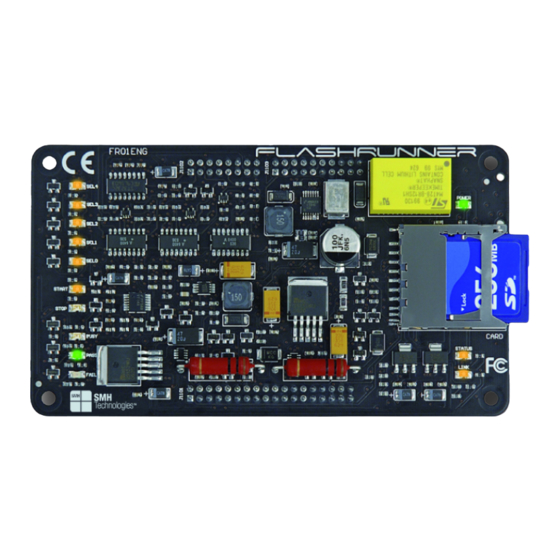
Page 15: Figure 1.1: Flashrunner Top Layer
FlashRunner FR01ENG User's Manual FlashRunner FR01ENG is composed of two layers: a bottom layer and a top layer. The bottom layer contains all of the FlashRunner electronics; the top layer has the function of protecting the bottom layer and replicating the status LEDs. -
Page 16: Programming Algorithms And Licenses
Figure 1.2: FlashRunner Bottom Layer (LEDs Side) Figure 1.3: FlashRunner Bottom Layer (Connectors Side) 1.3 Programming Algorithms and Licenses FlashRunner FR01ENG includes programming algorithms for several devices. In order to program a specific device, however, a specific license file for that device must be purchased. -
Page 17: Installing New Licenses
FlashRunner FR01ENG User's Manual Note: FlashRunner FR01ENG comes already preinstalled with the license(s) you specified at the moment of purchase. You can purchase additional licenses at any future moment. Programming algorithms and license files are stored in the SD card (see the FlashRunner Programmer’s Manual for more information). -
Page 18: Upgrading The Firmware
Overview Alternatively, you can use the FlashRunner Control Panel utility to install new programming algorithms and licenses. For more information on the FlashRunner Control Panel please refer to the FlashRunner Programmer’s Manual. 1.4 Upgrading the Firmware The FlashRunner firmware can be easily upgraded using the provided Control Panel utility. -
Page 19: System Setup
For how to connect to other target devices, please refer to the FlashRunner Programmer’s Manual. This chapter will explain how to set up FlashRunner FR01ENG for the first time. Although FlashRunner is typically used for standalone operations (Standalone mode), the examples in this chapter will use the host system to send commands to FlashRunner (Host mode). -
Page 20: Hardware Setup
Windows 2000 or Windows XP, you must log in as Administrator. 2.3 Hardware Setup To set up FlashRunner FR01ENG, you must follow the steps below, in the indicated order: Interface FlashRunner with your test/programming equipment; Connect FlashRunner to the host PC system;... -
Page 21: Figure 2.1: Typical Programming Connections
To Target Board Figure 2.1: Typical Programming Connections The specific ISP signals that must be routed from FlashRunner FR01ENG to your target board depend on the specific target device. Typical connections for all the device families supported by FlashRunner are shown in the... -
Page 22: Connecting Flashrunner To The Host Pc System
System Setup 2.3.2 Connecting FlashRunner to the Host PC System To connect FlashRunner FR01ENG to a host PC, you must provide a RS- 232 connector in your carrier board first, routing the appropriate signals from FlashRunner’s “CONTROL” connector to the RS-232 connector. -
Page 23: Figure 2.2: Flashrunner Control Panel, Communication Settings
FlashRunner FR01ENG User's Manual Figure 2.2: FlashRunner Control Panel, Communication Settings Click the “Connect” button. On the “Communication History” section, note the commands that have been sent and received. In this case, the SPING command is automatically sent to FlashRunner, which replies with the PONG>... -
Page 24: Figure 2.3: Flashrunner Control Panel, Target Device Configured
System Setup FlashRunner will respond to each command with the > string, indicating that the command has been successfully executed. After sending these commands, the Control Panel will look like the figure below. Figure 2.3: FlashRunner Control Panel, Target Device Configured When working with Freescale HC08 devices, FlashRunner requires you to specify the power up and power down times, in milliseconds. -
Page 25: Figure 2.4: Flashrunner Control Panel, Binary File Conversion
FlashRunner FR01ENG User's Manual FlashRunner format, click the “Create FlashRunner Binary Format” button. The following dialog box will appear. Figure 2.4: FlashRunner Control Panel, Binary File Conversion In the “Input” section, specify the source file to be converted, its format, and the address from which the file conversion will start (offset). -
Page 26: Figure 2.5: Flashrunner Control Panel, File Transfer
System Setup Figure 2.5: FlashRunner Control Panel, File Transfer Click the “...” button to browse for the image file to be sent, then click “Start” to begin the transfer. The file will be saved to the FlashRunner SD card, in the \BINARIES folder. We are now ready to start the actual programming part. -
Page 27: Figure 2.6: Flashrunner Control Panel, Target Device Programmed
FlashRunner FR01ENG User's Manual Figure 2.6: FlashRunner Control Panel, Target Device Programmed We are now done with programming the target device. Click the “Disconnect” button to free the serial port resource. For detailed information on all of the FlashRunner commands and their syntax, including specific commands for specific family of microcontrollers, please refer to the FlashRunner Programmer’s Manual, included (in PDF... -
Page 29: Connectors
FlashRunner FR01ENG User's Manual 3 Connectors 3.1 Overview FlashRunner connects to your programming/testing system through three header connectors: one groups ISP signals, one groups control signals, and one groups power signals. 3.2 Power Connector The “POWER” connector is used to power FlashRunner. This connector also includes reserved expansion lines, which must not be connected. -
Page 30: Control Connector
Connectors Table 3.1: Power Connector Signals Pin # Signal Name Description RESERVED Internal line for future expansion. Do not connect. RESERVED Internal line for future expansion. Do not connect. RESERVED Internal line for future expansion. Do not connect. RESERVED Internal line for future expansion. Do not connect. RESERVED Internal line for future expansion. -
Page 31: Figure 3.2: Control Connector
FlashRunner FR01ENG User's Manual TX_RS232 RX_RS232 STOP OPTO_5V START BUSY PASS 10 FAIL SEL0 12 SEL1 SEL2 14 SEL3 SEL4 16 OPTO_GND “CONTROL” Connector Figure 3.2: Control Connector... -
Page 32: Isp Connector
Connectors Table 3.2: Control Connector Signals Pin # Signal Name Description TX_RS232 TX (output, optoisolated, RS-232 levels) RX_RS232 RX (input, optoisolated, RS-232 levels) TX (output , open-drain, optoisolated, 0-5V levels) RX (input, optoisolated, 0-5V levels) STOP STOP (input , optoisolated, active low) OPTO_5V Optoisolation power supply (input, 5V). -
Page 33: Figure 3.3: Isp Connector
FlashRunner FR01ENG User's Manual DIO0/AO0 DIO1/AO1 VPROG0 VPROG0 DIO2 10 GND 12 VPROG0 DIO3 14 VPROG0 16 GND DIO4 18 VPROG1 20 VPROG1 DIO5 22 GND 24 GND DIO6 26 AIN0 28 GND CLKOUT 30 GND 32 GND 34 GND 36 GND “ISP”... -
Page 34: Table 3.3: Isp Connector Signals
Connectors Table 3.3: ISP Connector Signals Pin # Signal Name Description DIO0/AO0 Digital input/output 0 or analog output 0 Ground Ground Ground DIO1/AO1 Digital input/output 1 or analog output 1 VPROG0 Programmable voltage 0 (max 5.5V, 500mA) Ground VPROG0 Programmable voltage 0 (max 5.5V, 500mA) DIO2 Digital input/output 2 Ground... -
Page 35: Ate Connection Example
FlashRunner FR01ENG User's Manual 3.5 ATE Connection Example The figure below shows an example of connection between FlashRunner and an ATE system. In this example, the target board is automatically powered by FlashRunner through the VPROG0 line. POWER 9-24V To FlashRunner “POWER”... - Page 36 Connectors Note: all control signals are optoisolated. You must power the optoisolation circuitry through the OPTO_5V and OPTO_GND lines of the “CONTROL” connector. If your system doesn’t require optoisolation, just connect the OPTO_5V and OPTO_GND lines of the “CONTROL” connector to the 5V and GND lines (respectively) of the “POWER”...
-
Page 37: Technical Specifications
FlashRunner FR01ENG User's Manual Technical Specifications Absolute Maximum Ratings Table 4.1: Absolute Maximum Ratings Parameter Value “CONTROL” Connector Maximum input voltage on lines START, STOP, SEL[4..0], RX -2V to +9V Maximum input voltage on line RX_RS232 -25V to +25V Maximum input voltage on line OPTO_5V (reference OPTO_GND) Maximum current on lines BUSY, PASS,FAIL,TX -50mA to 1.5mA... -
Page 38: Dc Characteristics And Functional Operating Range
Technical Specifications DC Characteristics and Functional Operating Range Table 4.2: DC Characteristics and Functional Operating Range Value Parameter Condition “CONTROL” Connector (input low voltage) on lines START, STOP, The driver must be able to SEL[4..0], RX provide at least 5mA (input high voltage) on lines START, STOP, SEL[4..0], RX (input low voltage) on line RX_RS232... - Page 39 FlashRunner FR01ENG User's Manual Value Parameter Condition VPROG1 current (source) 250mA “POWER” Connector Supply voltage Power consumption 1.5A 5V line output current 100mA 5V line output voltage 4.75V 5.25V...
-
Page 40: Ac Characteristics
Technical Specifications AC Characteristics Table 4.3: AC Characteristics Value Parameter Condition on lines DIO[6..2], = 1.8V 40ns RISE PROG0 DIO[1..0], CLKOUT when Load: 470Ω//100pF = 3.3V 30ns configured as digital output (see figure 4.1a) PROG0 push-pull = 5V 25ns PROG0 = 1.8V 35ns on lines DIO[6..2],... -
Page 41: Physical And Environmental Specifications
FlashRunner FR01ENG User's Manual FlashRunner FlashRunner Figure 4.1: Load Conditions Physical and Environmental Specifications Table 4.4: Physical and Environmental Specifications Parameter Value Dimensions (with top panel) 130 x 74 x 27 mm Dimensions (without top panel) 130 x 74 x 22 mm “ISP”... -
Page 42: Figure 4.2: Bottom Layer (Connectors Side) Layout
Technical Specifications Figure 4.2: Bottom Layer (Connectors Side) Layout... - Page 44 SMH Technologies S.r.l. Via Giovanni Agnelli, 1 33083 Villotta di Chions (PN) Italy www.smh-tech.com info@smh-tech.com...
Need help?
Do you have a question about the FlashRunner FR01ENG and is the answer not in the manual?
Questions and answers