
Subscribe to Our Youtube Channel
Related Manuals for ASROCK IMB-1003


Summary of Contents for ASROCK IMB-1003
- Page 1 IMB-1003 User Manual Version 1.2 Updated April 2023 Copyright©2023 ASRockind INC. All rights reserved.
- Page 2 Version 1.0 Published September 2022 Copyright©2023 ASRockind INC. All rights reserved. Copyright Notice: No part of this documentation may be reproduced, transcribed, transmitted, or translated in any language, in any form or by any means, except duplication of documentation by the purchaser for backup purpose, without written consent of ASRockind Inc.
- Page 3 The terms HDMI® and HDMI High-Definition Multimedia Interface, and the HDMI logo are trademarks or registered trademarks of HDMI Licensing LLC in the United States and other countries. CAUTION: RISK OF EXPLOSION IF BATTERY IS REPLACED BY AN INCORRECT TYPE. DISPOSE OF USED BATTERIES ACCORDING TO THE INSTRUCTIONS.
-
Page 4: Table Of Contents
Contents 1 Introduction ............5 1.1 Package Contents ............5 1.2 Specifications ..............6 1.3 Motherboard Layout ............8 1.4 I/O Panel ................ 10 2 Installation ............12 2.1 Screw Holes ..............12 2.2 Pre-installation Precautions ........... 12 2.3 Installation of Memory Modules (SO-DIMM) ....13 2.4 Expansion Slot ............... -
Page 5: Introduction
Chapter 1: Introduction Thank you for purchasing ASRockind IMB-1003 motherboard, a reliable mother- board produced under ASRockind’s consistently stringent quality control. It delivers excellent performance with robust design conforming to ASRockind’s commitment to quality and endurance. In this manual, chapter 1 and 2 contain introduction of the motherboard and step-by- step guide to the hardware installation. -
Page 6: Specifications
1.2 Specifications Form Dimensions Mini-ITX (6.7-in x 6.7-in) Factor ® Intel Elkhart Lake SoC Processors IMB-1003J (J6412, QC, Max Speed Up to 2.6GHz, 10W) IMB-1003D (J6426, QC, Max Speed Up to 3.0GHz, 10W) Processor IMB-1003L (N6210, DC, Max Speed Up to System 2.6GHz, 6.5W) IMB-1003N (N6415, QC, Max Speed Up to... - Page 7 HDMI 1 x HDMI2.0b Ethernet 1 x 1 Gigabit LAN, 1 x 2.5 Gigabit LAN Rear I/O 2 x USB 3.2 (Gen1), 2 x USB 2.0 Audio 2 (Mic-In, Line-Out) COM1, COM3, COM4 (RS-232/422/485) 1 x PS/2 combo 2 x USB 3.2 Gen1 (1 x USB 3.2 header) 5 x USB 2.0 (2 x 2.54 pitch header, 1 x USB 2.0 Type-A vertical con) COM2, COM5, COM6 (RS-232)
-
Page 8: Motherboard Layout
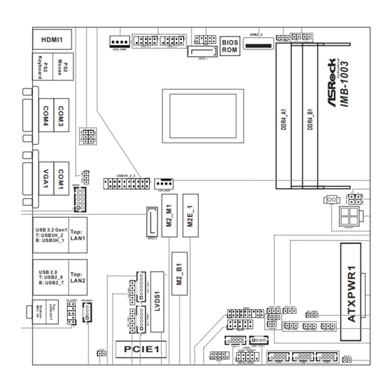
1.3 Motherboard Layout USB2_4 HDMI1 BIOS BLT_PWM1 TPM1 USB2_5_6 USB2_2_3 SATA_PWR1 SATA3_1 USB3H_2_3 VGA2 CPU_FAN1 BAT1 ATX12V1 USB 3.2 Gen1 Top: T: USB3H_2 LAN1 SATA3_2 B: USB3H_1 USB 2.0 Top: T: USB2_8 LAN2 B: USB2_7 HD_AUDIO1 SPEAKER1 JGPIO_PWR1 JGPIO_SET1 ESPI1 BLT_PWM2 CLRMOS1 CLRMOS2... - Page 9 1 : COM Port PWR Setting Jumper PWR_COM1 (For COM Port1) 2 : COM Port PWR Setting Jumpers PWR_COM3 (For COM Port3) PWR_COM4 (For COM Port4) 3 : USB3.2 Gen1 Connector (USB3H_2_3) 4 : SATA Power Output Connector 5 : USB2.0 Connectors (USB2_2_3, USB2_5_6) 6 : SATA3 Connector (SATA3_1) 7 : SPI TPM Header 8 : USB2.0 Port (USB2_4)
-
Page 10: I/O Panel
1.4 I/O Panel PS/2 Mouse Port USB 2.0 Ports (USB2_7_8) COM Port (COM3) (RS232/422/485)* USB 3.2 Gen1 Ports (USB3H_1_2) COM Port (COM1) (RS232/422/485)* D-Sub Port (VGA1) RJ45 LAN Port (LAN1)** COM Port (COM4) (RS232/422/485)* RJ45 LAN Port (LAN2)*** PS/2 Keyboard Port Line Out (Green) HDMI Port (HDMI1) Microphone (Pink) - Page 11 ** There are two LEDs on each LAN port. Please refer to the table below for the LAN port LED indications. ACT/LINK LED SPEED LED LAN Port Activity / Link LED Speed LED Status Description Status Description No Link 10Mbps connection Blinking Data Activity Orange...
-
Page 12: Installation
Chapter 2: Installation This is a Mini-ITX form factor (6.7" x 6.7", 17.0 x 17.0 cm) motherboard. Before you install the motherboard, study the configuration of your chassis to ensure that the motherboard fits into it. Make sure to unplug the power cord before installing or removing the motherboard. -
Page 13: Installation Of Memory Modules (So-Dimm)
2.3 Installation of Memory Modules (SO-DIMM) IMB-1003 motherboard provides two 260-pin DDR4 (Double Data Rate 4) SO-DIMM slots, and supports Dual Channel Memory Technology. 1. If you install one memory module only, please install it on DDR4_A1. 2. It is not allowed to install a DDR, DDR2 or DDR3 memory module into a DDR4 slot;... -
Page 14: Expansion Slot
2.4 Expansion Slots (PCI Express, M.2 and SIM Sockets) There is 1 PCI Express, 3 M.2 and 1 SIM sockets on this motherboard. PCIE slot: PCIE1 (PCIe x1 slot) is used for PCIe Gen3 x1 lane width cards. M.2 sockets: M2_M1 Socket (Key M) supports type 2242/2260/2280 M.2 SATA3 6.0 Gb/s and PCIe x1 for SSD. -
Page 15: Jumpers Setup
2.5 Jumpers Setup The illustration shows how jumpers are setup. When the jumper cap is placed on pins, the jumper is “Short”. If no jumper cap is placed on pins, the jumper is “Open”. The illustration shows a 3-pin jumper whose pin1 and pin2 are “Short”... - Page 16 Backlight Control Level 1-2: From eDP PWM to CON_LBKLT_CTL (3-pin BLT_PWM1) 2-3: From LVDS PWM to (see p.8, No. 9) CON_LBKLT_CTL Note: Please set to 1-2 when adjusting brightness by Brightness Control bar under OS. Please set to 2-3 when adjusting brightness by BLT_VOL1. eDP and LVDS Panel Power Select (LCD_VCC) Use this to set up the VDD power of the LVDS connector.
- Page 17 PWR_BAT2 Open: Normal Short: Charge Battery (2-pin PWR_BAT2) (see p.8 No. 12) DACC Jumper Open: Normal Short: Auto Clear CMOS (2-pin DACC2) (Power Off) (see p.8 No. 38) Note: Auto clear CMOS when system boot improperly Chassis Intrusion Headers This motherboard supports CASE OPEN detection feature (2-pin CI1, CI2: see p.8, No.
-
Page 18: Onboard Headers And Connectors
2.6 Onboard Headers and Connectors Onboard headers and connectors are NOT jumpers. Do NOT place jumper caps over these headers and connectors. Placing jumper caps over the headers and connectors will cause permanent damage of the motherboard! SATA3 Connectors These two Serial ATA3 (SATA3) connectors support (SATA3_1: see p.8, No. - Page 19 HDLED (Hard Drive Activity LED): Connect to the hard drive activity LED on the chassis front panel. The LED is on when the hard drive is reading or writing data. The front panel design may differ by chassis. A front panel module mainly consists of power switch, reset switch, power LED, hard drive activity LED, speaker and etc.
- Page 20 CPU Fan Connector Please connect the CPU fan cable to the connector and (4-pin CPU_FAN1) match the black wire to the +12V (see p.8 No. 11) CPU_FAN_SPEED FAN_SPEED_CONTROL ground pin. Though this motherboard provides 4-Pin CPU fan (Quiet Fan) support, the 3-Pin CPU fan still can work successfully even without the fan speed control function.
- Page 21 VGA Header PIN Signal Name PIN Signal Name DDC_CLK DDC_DATA (10-pin VGA1: see p.8, No. 42) HSYNC VSYNC BLUE GREEN SMBUS_TEST1 (4-pin SMB_TEST1: see p.8, No. 24) Signal Signal Signal Signal Name Name Name Name GPIO 2 SMB_CLK SMB_DATA SPI TPM Header (7-pin TPM1) (see p.8 No.
- Page 22 ATX Power Connector Please connect a DC (Input 12V-28V) 12V-28V power supply to this connector. (4-pin ATX12V1) 1-2: GND (see p.8 No. 14) 3-4: DC Input ATX Power Input Connector This motherboard provides a 24-pin ATX power connector. (24-pin ATXPWR1) To use a 20-pin ATX power (see p.8 No.
-
Page 23: Installation Of Rom Socket
2.7 Installation of ROM Socket * Do not apply force to the actuator cover after ic inserted. * Do not apply force to actuator cover when it is opening over 120 degree, Otherwise, the actuator cover may be broken. * The yellow dot (Pin1) on the ROM must be installed at pin1 position of the socket. -
Page 24: Uefi Setup Utility
Chapter 3: UEFI SETUP UTILITY 3.1 Introduction This section explains how to use the UEFI SETUP UTILITY to configure your system. The UEFI chip on the motherboard stores the UEFI SETUP UTILITY. You may run the UEFI SETUP UTILITY when you start up the computer. Please press <F2>... -
Page 25: Navigation Keys
3.1.2 Navigation Keys Please check the following table for the function description of each navigation key. Navigation Key(s) Function Description Moves cursor left or right to select Screens Moves cursor up or down to select items + / - To change option for the selected items <Enter>... -
Page 26: Advanced Screen
3.3 Advanced Screen In this section, you may set the configurations for the following items: CPU Configu- ration, Chipset Configuration, Storage Configuration, Super IO Configuration, ACPI Configuration, USB Configuration and Trusted Computing. Setting wrong values in this section may cause the system to malfunction. -
Page 27: Cpu Configuration
3.3.1 CPU Configuration Active Processor Cores Select the number of cores to enable in each processor package. CPU C States Support Enable CPU C States Support for power saving. It is recommended to keep C3, C6 and C7 all enabled for better power saving. Intel Virtualization Technology When this option is set to [Enabled], a VMM (Virtual Machine Architecture) can utilize the additional hardware capabilities provided by Vanderpool... -
Page 28: Chipset Configuration
3.3.2 Chipset Configuration Above 4G Decoding Enable or disable 64bit capable Devices to be decoded in Above 4G Ad- dress Space (only if the system supports 64 bit PCI decoding). VT-d ® ® Use this to enable or disable Intel VT-d technology (Intel Virtualization Technology for Directed I/O). - Page 29 The default values of Active LVDS and Panel Type Selec- tionwill be changed only when the users manually adjust them. They will keep at the default values no matter you clear CMOS, use Instant Flash or press <F9>. Onboard LAN 1 This allows you to enable or disable the Onboard LAN 1 feature.
-
Page 30: Storage Configuration
3.3.3 Storage Configuration SATA Controller(s) Use this item to enable or disable the SATA Controller feature. SATA Mode Selection Use this to select SATA mode. The default value is [AHCI]. SATA Aggressive Link Power Management Use this item to configure SATA Aggressive Link Power Management. Hard Disk S.M.A.R.T. -
Page 31: Super Io Configuration
3.3.4 Super IO Configuration COM1 Use this to enable or disable COM1. Type Select Use this to select COM1 port type: [RS232], [RS422] or [RS485]. COM2 Use this to enable or disable COM2. COM3 Use this to enable or disable COM3. Type Select Use this to select COM3 port type: [RS232], [RS422] or [RS485]. -
Page 32: Acpi Configuration
3.3.5 ACPI Configuration Suspend to RAM Use this item to select whether to auto-detect or disable the Suspend-to- RAM feature. Select [Auto] will enable this feature if the OS supports it. PCIE Devices Power On Use this item to enable or disable PCIE devices to turn on the system from the power-soft-off mode. -
Page 33: Usb Configuration
3.3.6 USB Configuration USB Power Control [Always Enable] - Enable USB power in S0/S3/S4/S5. [Default Setting] - Enable USB power in S0/S3, disable USB power in S4/ M.2 Key_B Function Enable or disable M.2 Key-B function. -
Page 34: Trusted Computing
3.3.7 Trusted Computing Security Device Support Enable or disable BIOS support for security device. -
Page 35: Hardware Health Event Monitoring Screen
3.4 Hardware Health Event Monitoring Screen In this section, it allows you to monitor the status of the hardware on your system, including the parameters of the CPU temperature, motherboard temperature, CPU fan speed, chassis fan speed, and the critical voltage. CPU_FAN1 Setting This allows you to set CPU_FAN1’s speed. -
Page 36: Security Screen
3.5 Security Screen In this section, you may set, change or clear the supervisor/user password for the system. Supervisor Password Set or change the password for the administrator account. Only the ad- ministrator has authority to change the settings in the UEFI Setup Utility. Leave it blank and press enter to remove the password. -
Page 37: Boot Screen
3.6 Boot Screen In this section, it will display the available devices on your system for you to config- ure the boot settings and the boot priority. Boot From Onboard LAN Use this item to enable or disable the Boot From Onboard LAN feature. Setup Prompt Timeout This shows the number of seconds to wait for setup activation key. -
Page 38: Exit Screen
3.7 Exit Screen Save Changes and Exit When you select this option, it will pop-out the following message, “Save configuration changes and exit setup?” Select [OK] to save the changes and exit the UEFI SETUP UTILITY. Discard Changes and Exit When you select this option, it will pop-out the following message, “Discard changes and exit setup?”...
Need help?
Do you have a question about the IMB-1003 and is the answer not in the manual?
Questions and answers