Table of Contents
Advertisement
Quick Links
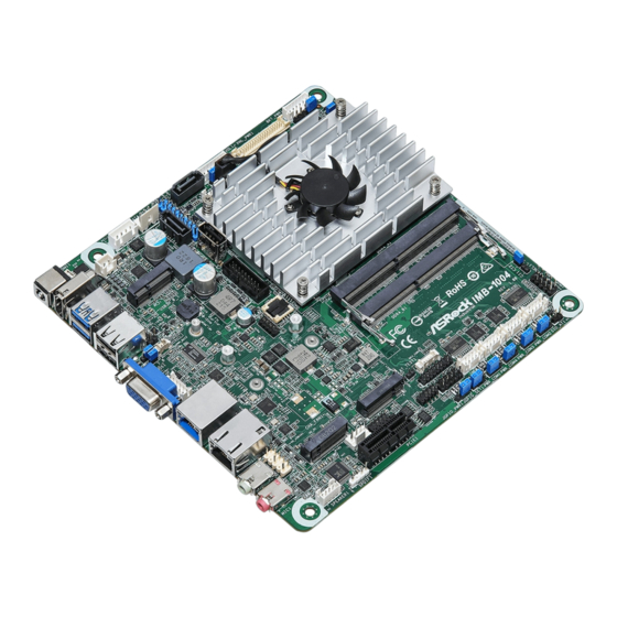
IMB-1004
®
The terms HDMI
and HDMI High-Definition
Multimedia Interface, and the HDMI logo are
trademarks or registered trademarks of HDMI
Licensing LLC in the United States and other
countries.
Revision History
Date
Description
January 27, 2022
First Release
1 : 2-pin UPS Module Power Input Connector
Pin1: GND
Pin2: DC Input
1
2 : M.2 Key-E Socket (M2_E1)
NA
NA
NA
3 : 4-pin DC-in PWR Connector (Input +12V
~+28V) & UPS Module Power Output
Connector
Pin1 and Pin4: GND
Pin2 and Pin3: DC Input
4 : SATA Power Output Connector
5 : SATA3 Connector (SATA3_2)
DUMMY
6 : USB2.0 Connectors
GND
(USB2_2_3,
+B
USB2_5_6)
-B
USB_PWR
7 : SATA3 Connector (SATA3_1)
Jumpers and Headers Setting Guide
8 : SMB_TEST1
Signal
PIN
PIN
Name
1
GPIO
2 SMB_CLK
9 : Backlight Volume Control (BLT_VOL1)
10 : LVDS Panel Connector
1
2
1
11 : eDP and LVDS Panel Power Select
(LCD_VCC) (PNL_PWR1)
GND
+5V
1-2: LCD_VCC: +3V
1
2-3: LCD_VCC: +5V
+12V
GND
4-5: LCD_VCC: +12V
12 : Brightness Control Mode
GND
(BLT_PWM1)
+A
-A
1-2: From eDP PWM to CON_LBKLT_CTL
USB_PWR
2-3: From LVDS PWM to CON_LBKLT_CTL
1
* Please set to 1-2 when adjusting brightness by Brightness
Control bar under OS.
* Please set to 2-3 when adjusting brightness by BLT_VOL1.
1
Signal
Signal
Signal
PIN
PIN
Name
Name
Name
3
SMB_DATA
4
GND
PIN
Signal Name
1
1
GPIO_VOL_UP
2
GPIO_VOL_DW
3
PWRDN
4
BRIGHTNESS_UP
5
BRIGHTNESS_DW
6
GND
7
GND
39
40
13 : CON_LBKLT_EN and CON_LBKLT_CTL
Voltage Level (BLT_EN_PWM1)
1-2: 5V Level
2-3: 3V Level
14 : Backlight Power Connector (BLT_PWR1)
PIN
1
1
2
3
CON_LBKLT_CTL
4
CON_LBKLT_EN
5
LCD_BLT_VCC
6
LCD_BLT_VCC
15 : eDP and LVDS Backlight Power Select
(LCD_BLT_VCC) (BKT_PWR1)
1-2: LCD_BLT_VCC: +5V
2-3: LCD_BLT_VCC: +12V
4-5: LCD_BLT_VCC: DC Input
16 : 4-Pin CPU FAN Connector (+12V)
FAN_SPEED_CONTROL
CPU_FAN_SPEED
+12V
GND
17 : USB2.0 Connector (USB2_4)
18 : USB3.2 Gen1 Connector (USB3H_2_3)
1
Dummy
IntA_PA_D+
IntA_PB_D+
IntA_PA_D-
IntA_PB_D-
GND
GND
IntA_PA_SSTX+
IntA_PB_SSTX+
IntA_PA_SSTX-
GND
IntA_PB_SSTX-
GND
IntA_PA_SSRX+
IntA_PB_SSRX+
IntA_PA_SSRX-
IntA_PB_SSRX-
Vbus
Vbus
19 : SPI TPM Header
Signal Name
GND
GND
1
Advertisement
Table of Contents

Subscribe to Our Youtube Channel
Related Manuals for ASROCK IMB-1004


Summary of Contents for ASROCK IMB-1004
- Page 1 Jumpers and Headers Setting Guide IMB-1004 ® The terms HDMI and HDMI High-Definition Multimedia Interface, and the HDMI logo are trademarks or registered trademarks of HDMI Licensing LLC in the United States and other countries. Revision History Date Description January 27, 2022...
- Page 2 20 : Chassis Intrusion Headers 27 : Digital Input/Output Pin Header (JGPIO1) 35 : M.2 Key-M Socket (M2_M1) CI1: Signal Close: Active Case Open Open: Normal Cl2: Signal Signal Signal PIN Signal Name PIN PIN Signal Name Name Name Name Close: Normal PMC_TGPIO0 SOC_D01...
Need help?
Do you have a question about the IMB-1004 and is the answer not in the manual?
Questions and answers