
Related Manuals for Maxon TUK-A-WAY MTB-25


Summary of Contents for Maxon TUK-A-WAY MTB-25
- Page 1 M-00-40 REV. F AUGUST 2012 O P E R A T I O N MANUAL MTB-25 & MTB-30 © MAXON Lift Corp. 2012...
-
Page 3: Table Of Contents
TABLE OF CONTENTS WARNINGS ................4 LIFTGATE TERMINOLOGY ............5 DECALS ..................6 FORKLIFT ADVISORY ............. 8 ROADSIDE ADVISORY ............9 OPERATION ................10... -
Page 4: Warnings
5. Comply with all attached instruction decals and warning decals. 6. Keep decals clean and legible. If decals are illegible or missing, have them replaced. Get free replacement decals from Maxon. 7. Never drive a forklift on the Liftgate Platform. -
Page 5: Liftgate Terminology
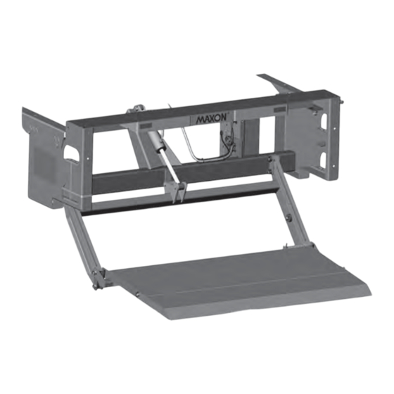
LIFTGATE TERMINOLOGY CONTROL EXTENSION CONTROL HANDLE MAIN PLATE SWITCH FRAME PUMP BOX PARALLEL PLATFORM LIFT CYLINDER LIFT FRAME RAMP FLIPOVER WEDGE FLIPOVER SPECIAL PROFILE FLIPOVER... -
Page 6: Decals
DECALS NOTE: Ensure there is no residue, dirt, or corrosion where decals are attached. If necessary, clean surface before attaching decals. NOTE: Decals for streetside are included with the streetside control switch kit. DECAL P/N 265438 OR DECAL P/N 265438 OR P/N 265439 P/N 265439 (SEE FIG. - Page 7 DECAL (2 PLACES, MTB-25 ONLY) P/N 265438 DECAL (2 PLACES, MTB-30 ONLY) P/N 265439 WARNING DECAL (2 PLACES) P/N 282847-02 FIG. 7-1...
-
Page 8: Forklift Advisory
FORKLIFT ADVISORY WARNING Keep forklift OFF of platform. FIG. 8-1... -
Page 9: Roadside Advisory
NOTE: MAXON recommends placing at least 2 traffi c cones on the traffi c side of the platform loading area as illustrated below. Remove cones after platform is stowed and before moving the vehicle. -
Page 10: Operation
OPERATION 1. Standing to the side of platform (FIG. 10-1A), push down control handle (FIG. 10-1B) and push the toggle switch to LOWER position as shown in FIG. 10-1C. Release control handle after platform is lowered about 2 inches. FIG. 10-1C FIG. - Page 11 3. Unfold the fl ipover as shown in FIGS. 11-1 & 11-2. If platform is equipped with retention ramp, unfold to ramp. First, push down on retention ramp (FIG. 11-3A) to release the tension on the latch handle (FIG. 11-3B). Next, hold down RAMP FLIPOVER on the latch handle and unfold FIG.11-1...
- Page 12 OPERATION - Continued NOTE: While operating the Liftgate, you can stop the platform immediately by releasing the toggle switch. 4. Raise the platform (FIG. 12-1A) by pushing the toggle switch to the RAISE position (FIG. 12-1B). If loading (or unloading) the platform, wait a second before releasing the toggle switch after platform reaches bed height.
- Page 13 5. Make sure platform is positioned like the YES illustrations in FIG. 13-1A and FIG. 13-1B. At bed height with no load, out- board edge of platform must be higher than extension plate (FIG. 13-1A). At ground level, LEVEL with no load, the platform must LINE not sag (FIG.
- Page 14 OPERATION - Continued WARNING A load should never extend past the edges of the platform. Do not place unstable loads on platform and do not allow load to exceed the lifting capacity of the Liftgate. If standing on platform, do not allow your feet to extend beyond the inboard edge of the platform.
- Page 15 10. Lower the platform to ground INBOARD level (FIG. 15-1). Move load EDGE off the platform. PLATFORM UNLOADING PLATFORM AT GROUND LEVEL FIG. 15-1 WARNING Never move the vehicle unless the Liftgate is properly stowed. 11. Before moving the vehicle, prepare the Liftgate as fol- lows.
- Page 16 OPERATION - Continued 13. Fold fl ipover (FIG. 16-1). If the platform is equipped with retention ramp (FIG. 16-2A), fold ramp to stowed position before folding fl ipover (FIG. 16-2B). RAMP FLIPOVER FIG. 16-1 STOWING RETENTION RAMP FIG. 16-2B SPECIAL PROFILE FLIPOVER FIG.
- Page 17 CAUTION Stow Liftgate under hydraulic pressure. To prevent damage, make sure platform loop is not resting on safety hook (FIG. 17-1C). 15. Stow the platform (FIG. 17-1A) by pushing the toggle switch to the RAISE position (FIG. 17-1B). Wait a second, after platform is stowed all the way, before releasing toggle switch.
Need help?
Do you have a question about the TUK-A-WAY MTB-25 and is the answer not in the manual?
Questions and answers