Table of Contents
Advertisement
Quick Links
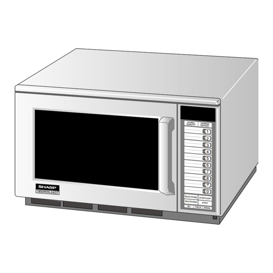
180 0W /R-2 4GT
R-24GT-F
BEFORE SERVICING ...................................................................................................... INSIDE FRONT COVER
WARNING TO SERVICE PERSONEL .................................................................................................................. 1
MICROWAVE MEASUREMENT PROCEDURE ................................................................................................... 2
FOREWORD .......................................................................................................................................................... 3
PRODUCT SPECIFICATIONS .............................................................................................................................. 4
GENERAL INFORMATION ................................................................................................................................... 4
OPERATION .......................................................................................................................................................... 6
TROUBLE SHOOTING GUIDE/ TEST PROCEDURE ........................................................................................ 11
TOUCH CONTROL PANEL ................................................................................................................................. 21
COMPONENT REPLACEMENT AND ADJUSTMENT PROCEDURE ................................................................ 31
PICTORIAL DIAGRAM ........................................................................................................................................ 37
CONTROL PANEL CIRCUIT ............................................................................................................................... 38
PRINTED WIRING BOARD ................................................................................................................................. 40
PARTS LIST ........................................................................................................................................................ 41
PACKING AND ACCESSORIES ......................................................................................................................... 46
SHARP CORPORATION
SERVICE MANUAL
MODELS
DOUB LE
QUAN TITY
EXPR ESS
DEFR OST
1
11
12
2
13
3
14
4
15
5
6
16
17
7
8
18
9
19
In the interest of user-safety the oven should be restored to its original
0
20
SELE CTATI ME
STOP /CLEA R
SELEC TAPOW ER
condition and only parts identical to those specified should be used.
STAR T
SET
CHEC K
SIGNA L
WARNING TO SERVICE PERSONNEL: Microwave ovens contain
circuitry capable of producing very high voltage and current,
contact with following parts may result in a severe, possibly fatal,
electrical shock. (High Voltage Capacitor, High Voltage Power
Transformer, Magnetron, High Voltage Rectifier Assembly, High
Voltage Harness etc..)
TABLE OF CONTENTS
COMMERCIAL
MICROWAVE OVENS
R-23GT-F
R-24GT-F
This document has been published to be used for after
sales service only.
The contents are subject to change without notice.
R-23GT-F
R-24GT-F
S0512R24GTF//
Page
Advertisement
Table of Contents

Subscribe to Our Youtube Channel
Related Manuals for Sharp R-23GT-F


Summary of Contents for Sharp R-23GT-F
-
Page 1: Table Of Contents
R-23GT-F R-24GT-F SERVICE MANUAL S0512R24GTF// COMMERCIAL MICROWAVE OVENS R-23GT-F MODELS R-24GT-F DOUB LE QUAN TITY EXPR ESS DEFR OST In the interest of user-safety the oven should be restored to its original 180 0W /R-2 4GT SELE CTATI ME STOP /CLEA R SELEC TAPOW ER condition and only parts identical to those specified should be used. -
Page 2: Precautions To Be Observed Before And During Service To Avoid Possible Exposure To Excessive Microwave Energy
Before servicing an operative unit, perform a microwave emission check as per the Microwave Measurement Procedure outlined in this service manual. If microwave emissions level is in excess of the specified limit, contact SHARP ELECTRONICS CORPORATION immediately @1-800-237-4277. If the unit operates with the door open, service person should 1) tell the user not to operate the oven and 2) contact SHARP ELECTRONICS CORPORATION and the Food and Drug Administration's Center for Devices and Radiological Health immediately. -
Page 3: Warning To Service Personel
R-23GT-F R-24GT-F WARNING TO SERVICE PERSONNEL Microwave ovens contain circuitry capable of pro- ducing very high voltage and current, contact with following parts may result in a severe, possibly fatal, electrical shock. (Example) High Voltage Capacitor, High Voltage Power Trans- former, Magnetron, High Voltage Rectifier Assem- bly, High Voltage Harness etc.. -
Page 4: Microwave Measurement Procedure
R-23GT-F R-24GT-F MICROWAVE MEASUREMENT PROCEDURE A. Requirements: 1) Microwave leakage limit (Power density limit): The power density of microwave radiation emitted by a microwave oven should not exceed 1mW/cm at any point 5cm or more from the external surface of the oven, measured prior to acquisition by a... -
Page 5: Foreword
MICROWAVE OVEN GENERAL INFORMATION R-23GT-F/ R-24GT-F FOREWORD This Manual has been prepared to provide Sharp Electronics Corp. OPERATION Service Personnel with Operation and Service Information for the SHARP MICROWAVE OVENS, R-23GT-F/ R-24GT-F. It is recommended that service personnel carefully study the entire text of... - Page 6 WARNING: Improper use of the grounding plug can result in a risk of electric shock. The electrical requirements are 230/208 Volt, 60 Hz, AC only, 15 Amp or more (R-23GT-F) and 20 Amp or more (R-24GT-F) fused electrical supply. It is recommended that a separate circuit serving only this appliance be provided.
- Page 7 R-23GT-F R-24GT-F VOLTAGE SELECT Power supply cord The oven has been preset for 230V operation. If you need to change this oven for 208V operation, follow instructions below. 1. Unplug oven. 2. Remove one screw(A) from the Voltage Select Cover located on back of the oven near the bottom.
-
Page 8: Operation
R-23GT-F R-24GT-F OPERATION DESCRIPTION OF OPERATING SEQUENCE 7. The monitor switch (1) is electrically monitoring the operation The following is a description of component functions during oven operation. of the secondary interlock switch (1) and primary interlock relay (1), and monitor switch (2) is electrically monitoring the... - Page 9 R-23GT-F R-24GT-F TWO MAGNETRON OPERATION SYSTEM OPERATION OF MAGNETRON Two magnetrons (1), (2) are equipped in order to get higher COMMERCIAL microwave power output. The primary windings of the power FREQUENCY (60HZ) transformers (1), (2) are connected so that each magnetron...
- Page 10 R-23GT-F R-24GT-F SCHEMATIC NOTE: CONDITION OF OVEN 1. FOR 1MINUTE AFTER DOOR OPENED. 2. " . " APPEARS ON DISPLAY. NOISE PRIMARY FILTER MAGNETRON INTERLOCK TEMP. FUSE (1) POWER RELAY (1) TRANSFORMER (1) MAGNETRON FUSE 20A OVEN TEMP. FUSE (2) TEMP.
- Page 11 R-23GT-F R-24GT-F DESCRIPTION AND FUNCTION OF COMPONENTS DOOR OPEN MECHANISM Functions: With the door shut, the contacts of the door sensing switch and 1. The door release lever is pulled. the secondary interlock switches (1), (2) are closed and the 2.
- Page 12 R-23GT-F R-24GT-F OVEN THERMISTOR (2) SELECT SWITCH AND ELECTRICAL COMPONENTS CONDITION This thermistor detects temperature of the oven cavity bottom plate. The thermistor is a negative temperature coefficient type. SWITCH NO. ELECTRICAL PARTS The temperature is detected through the resistance of the Touch control unit thermistor.
- Page 13 R-23GT-F R-24GT-F TROUBLESHOOTING GUIDE Never touch any part in the circuit with your hand or an uninsulated tool while the power supply is connected. When troubleshooting the microwave oven, it is helpful to follow the Sequence of Operation in performing the checks. Many of the possible causes of trouble will require that a specific test be performed.
- Page 14 R-23GT-F R-24GT-F...
- Page 15 Check for continuity of the coils with an ohmmeter. On the R x 1 scale, the resistance of the primary coil should be less than 1 ohm and the resistance of the high voltage coil should be approximately 65 ohms (R-23GT-F: RTRN-A454WRE0) and approximately 60 ohms (R-24GT-F: RTRN-A455WRE0); the resistance of the filament coil should be less than 1 ohm.
- Page 16 R-23GT-F R-24GT-F TEST PROCEDURES PROCEDURE COMPONENT TEST LETTER 6. Reinstall the outer case (cabinet). 7. Reconnect the power supply cord after the outer case is installed. 8. Run the oven and check all functions. (HIGH VOLTAGES ARE PRESENT AT THE HIGH VOLTAGE TERMINAL, SO DO NOT ATTEMPT TO MEASURE THE FILAMENT AND HIGH VOLTAGE.)
- Page 17 R-23GT-F R-24GT-F TEST PROCEDURES PROCEDURE COMPONENT TEST LETTER 5. Reconnect all leads removed from components during testing. 6. Reinstall the outer case (cabinet). 7. Reconnect the power supply cord after the outer case is installed. 8. Run the oven and check all functions.
- Page 18 R-23GT-F R-24GT-F TEST PROCEDURES PROCEDURE COMPONENT TEST LETTER BLOWN MONITOR FUSE TEST 1. Disconnect the power supply cord, and then remove outer case. 2. Open the door and block it open. 3. Discharge two high voltage capacitors. 4. If the monitor fuse is blown when the door is opened, check the primary interlock relays RY2, RY3, secondary interlock switches (1), (2) and monitor switches (1), (2) according to the "TEST PROCEDURE"...
- Page 19 R-23GT-F R-24GT-F TEST PROCEDURES PROCEDURE COMPONENT TEST LETTER Room Temp. 59˚F (15˚C) 68˚F (20˚C) 77˚F (25˚C) Resistance Approx. 373 kΩ Approx. 292 kΩ Approx. 231 kΩ If the meter does not indicate above resistance, replace the thermistor. 4-2. OVEN THERMISTOR (1) TEST Disconnect connector-B from the CPU unit.
- Page 20 R-23GT-F R-24GT-F TEST PROCEDURES PROCEDURE COMPONENT TEST LETTER Before testing, 1) Disconnect the power supply cord, and then remove outer case. 2) Open the door and block it open. 3) Discharge two high voltage capacitors. 4) Disconnect the leads to the primary of the power transformer.
- Page 21 R-23GT-F R-24GT-F TEST PROCEDURES PROCEDURE COMPONENT TEST LETTER KEY UNIT TEST 1. Disconnect the power supply cord, and then remove outer case. 2. Open the door and block it open. 3. Discharge two high voltage capacitors. 4. If the display fails to clear when the STOP/CLEAR pad is depressed, first verify the flat ribbon cable is making good contact, verify that the door sensing switch (stop switch) operates properly;...
- Page 22 R-23GT-F R-24GT-F TEST PROCEDURES PROCEDURE COMPONENT TEST LETTER 13. Reconnect the power supply cord after the outer case is installed. 14. Run the oven and check all function. FOIL PATTERN ON THE PRINTED WIRING BOARD TEST To protect the electronic circuits, this model is provided with a fine foil pattern added to the primary on the PWB, this foil pattern acts as a fuse.
-
Page 23: Touch Control Panel
R-23GT-F R-24GT-F TOUCH CONTROL PANEL ASSEMBLY OUTLINE OF TOUCH CONTROL PANEL The touch control section consists of the following units as 15) Oven Cavity Temperature Detecting Circuit shown in the touch control panel circuit. This is a circuit for transmitting output change of thermistor (Oven thermistor (2)) to IC1. - Page 24 R-23GT-F R-24GT-F VOLTAGE REGULATION FOR "ERROR" INDICATION Voltage Input to Input to regulation 208V 230V *Normal +6% excel. 208.0--220.48 230.0--243.8 *Normal -9% excel. 189.28--208.0 209.3--230.0 *Error.or +6% to 220.48 243.8 indication +13% excel. 235.04 259.9 range -9% to 189.28 209.3 -13% excel.
- Page 25 R-23GT-F R-24GT-F DESCRIPTION OF LSI LSI(IZA633DR) The I/O signal of the LSI(IZA633DR) is detailed in the following table. Pin No. Signal Description Power source voltage: +5V. VC voltage of power source circuit input. Connected to GND VEE/AVSS VREF Connected to VC. (+5V) Temperature measurement input: INTAKE THERMISTOR.
- Page 26 R-23GT-F R-24GT-F Pin No. Signal Description Digit selection signal. The relation between digit signal and digit are as ß(60Hz) follows: Digit signal Digit P42 ..... 1st. P43 ....2nd. P44 ..... 3rd. P45 ..... 4th. Normally, one pulse is output in every ß period, and input to the grid of the light-emitting diode.
- Page 27 R-23GT-F R-24GT-F Pin No. Signal Description 41-48 P17-P10 Segment data signal. Signal similar to P21. 49-56 P07-P00 Segment data signal. Signal similar to P21. 57-59 P37-P35 Terminal not used. Key strobe signal. Signal applied to touch-key section. A pulse signal is input to P27, P26, P25 and P24 terminals while one of G4 line keys on key matrix is touched.
- Page 28 R-23GT-F R-24GT-F SERVICING 1. Precautions for Handling Electronic Components 5) Re-connect the power supply cord after the outer case This unit uses CMOS LSI in the integral part of the circuits. is installed. When handling these parts, the following precautions should 6) Run the oven and check all functions.
- Page 29 R-23GT-F R-24GT-F 3) Practice for inputting total using times (Ex. 310000 times). PROCEDURE FOR CHECKING/CLEARING SERVICE COUNTS OF MICROWAVE OVEN ... Flashing / ... 0.1sec BUZZER DISPLAY INDICATOR TONE The following procedure enables the servicer to obtain the total (Door close)
- Page 30 R-23GT-F R-24GT-F 5) Practice for cancelling total using times and total operation DISPLAY PAUSE time (user and service) and all other counter. End of each stage ... Flashing / ... 0.1sec BUZZER After 10% of total cooking time is passed...
- Page 31 R-23GT-F R-24GT-F MEMORY READJUSTMENT PROCEDURE 1. To set the standard voltage When the IC2 is changed in the control unit, the standard voltage must be set again for power supply check. The power supply must be set 230V within ± 1V, and 230V connector in control unit installed.
- Page 32 R-23GT-F R-24GT-F 2]. [JUDGMENT PROCEDURE FOR UPPER MAGNETRON AND ITS CIRCUIT] Disconnect the power supply cord. Disconnect lead wires to the interlock relay RY3 to avoid operation of lower magnetron circuit. Reconnect power supply Heating for one minute. If EE1 is indicated, carry out Test procedures A-J and find out the defective part.
-
Page 33: Component Replacement And Adjustment Procedure
1. Door does not close firmly. WARNING FOR WIRING To prevent an electric shock, take the following precau- Oven cavity. tions. 3) Sharp edge: 1. Before wiring, Bottom plate, Oven cavity, Waveguide flange, Chassis 1) Disconnect the power supply cord. support and other metallic plate. - Page 34 R-23GT-F R-24GT-F POWER TRANSFORMERS (1) AND/OR (2) REMOVAL 1. Disconnect the power supply cord and then remove outer from high voltage capacitors (1) and/or (2). case and rear cabinet, referring to "OUTER CASE, REAR 8. Disconnect the high voltage wire lead(s) from power CABINET AND POWER SUPPLY CORD REMOVAL".
- Page 35 "OUTER CASE, REAR CABINET AND 3. Where the portions have been snipped off bend the portions POWER SUPPLY CORD REMOVAL". flat. No sharp edge must be evident after removal of the 2. Open the oven door and block it open. stirrer motor cover.
- Page 36 R-23GT-F R-24GT-F CONTROL PANEL ASSEMBLY AND CONTROL UNIT REMOVAL CONTROL PANEL ASSEMBLY REMOVAL upward. 12.Now, the control unit and control panel frame (with key) are The complete control panel should be removed for replace- free. ment of components. To remove the control panel, proceed as...
-
Page 37: Pictorial Diagram
R-23GT-F R-24GT-F procedure. of the latch hook. DOOR SENSING SWITCH 2) Fasten both switches together to latch hook with one (1) Push the two (2) tabs outward and pull switch forwards to screw and nut. release switch. SECONDARY INTERLOCK SWITCHES... - Page 38 R-23GT-F R-24GT-F Note: After any service to the door; This function does not require that door be air-tight, (A) Make sure that door sensing switch, secondary moisture (condensation)-tight or light-tight. Therefore, interlock switches (1), (2) and monitor switches (1), (2) occasional appearance of moisture, light or sensing are operating properly.
- Page 39 R-23GT-F R-24GT-F...
- Page 40 R-23GT-F R-24GT-F...
- Page 41 R-23GT-F R-24GT-F...
-
Page 42: Printed Wiring Board
R-23GT-F R-24GT-F Figure S-3. Printed Wiring Board... -
Page 43: Parts List
1-16 QFS-TA015WRE0 Temperature fuse 120C (OVEN) 1-17 RTRN-A454WRE0 Power transformer [R-23GT-F] 1-17 RTRN-A455WRE0 Power transformer [R-24GT-F] When the new high voltage capacitor RC-QZA260WRE0 is used instead of old part (RC-QZA191WRE0), please use the new capacitor holder LBNDKA068WRP0, because the sizes of the old high voltage capacitor and the new one are different. - Page 44 1/4W R101 VRD-Q12EF104J Resistor 100k ohm 1/4W R102 VRD-Q12EF472J Resistor 4.7k ohm 1/4W (J5) VRD-Q12EF103J Resistor 10k ohm 1/4W [R-23GT-F] (J5) VRD-Q12EF203J Resistor 20k ohm 1/4W [R-24GT-F] (J6) VRD-Q12EF203J Resistor 20k ohm 1/4W [R-23GT-F] (J6) VRD-Q12EF103J Resistor 10k ohm 1/4W [R-24GT-F]...
- Page 45 Cushion 4-30 LANGKA679WRPZ Fixing angle S 4-31 HDECQA147WRM0 Corner cap right 4-32 LANGFA195WRW0 Chassis support 4-33 LBSHC0006YBE0 Cord bushing [R-23GT-F] [R-24GT-F] 4-34 LANGQA593WRPZ Blower motor angle 4-35 FFIL-A003WRK0 Air intake filter assembly 4-36 HDECEA001WRP0 Decoration sash 4-37 HDECQA146WRM0 Corner cap left...
-
Page 46: Packing And Accessories
1. MODEL NUMBER 2. REF. NO. 3. PART NO. 4. DESCRIPTION Order Parts from the authorized SHARP parts Distributor for your area. Defective parts requiring return should be returned as indicated in the Service Policy. PACKING AND ACCESSORIES TOP PAD ASSEMBLY... - Page 47 R-23GT-F R-24GT-F OVEN AND CABINET PARTS 7-19 4-20 6-11 7-22 2-5-2 4-23 2-5-1 4-30 7-22 7-22 4-33 6-12 4-43 7-22 7-22 7-15 7-22 7-22 7-21 7-22 4-26 7-22 4-42 7-22 7-20 4-41 7-21 7-22 7-22 1-10 1-16 1-10 4-27 4-25...
- Page 48 Actual wire harness may be different from illustration. To high voltage capacitor 6-16 COPYRIGHT © 2005 BY SHARP CORPORATION ALL RIGHTS RESERVED. No part of this publication may be reproduced, stored in retrieval systems, or transmitted in any form or by any means,...
Need help?
Do you have a question about the R-23GT-F and is the answer not in the manual?
Questions and answers