Table of Contents
Advertisement
Quick Links
Advertisement
Table of Contents

Related Manuals for Emerson Copeland Large ZXD120BE-TFM


Summary of Contents for Emerson Copeland Large ZXD120BE-TFM
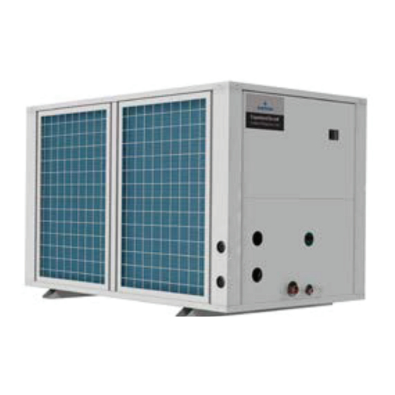
- Page 1 Large ZX Condensing Unit User Manual - Dubai Sourced Units...
-
Page 2: Table Of Contents
Table of contents Introduction Safety Information Nomenclature Operating Envelope Technical data Features & Bene ts Physical Layout CoreSense Controller Network Wiring Electrical connection Installation, System Processing and Commissioning Troubleshooting System Start-Up and Operational Check Sheet... -
Page 3: Introduction
This is best in class unit within the capacity and operating range available in the market. Emerson ZX series has been highly successful in global market and enjoys proven success with its energy savings and customer friendly electronic features. -
Page 4: Safety Information
1. Safety Information Installation and commissioning work on CDU shall be carried out only by qualified, refrigeration personnel who have been trained and instructed. Large ZX condensing unit is manufactured according to the latest safety standards. Emphasis has been placed on the user’s safety. For relevant standards please refer to the manufacturer’s declaration, available on request. - Page 5 Damage to the unit caused by the transportation / handling should fall within the category of insurance claims and not be a manufacturing defect. It is also advisable to inspect the rest of the unit for any physical damage and inform Emerson or authorized distributor.
-
Page 6: Nomenclature
2. Nomenclature 3. Scope of Supply ZXD 12 to 20 HP ZXLD 12 to 20 HP Liquid Line Filter Drier Moisture Indicator Oil Separator Oil Reservoir Combination Oil Separator / Reservoir Accumulator LP Transducer HP Transducer Fixed LP Safety Switch Adjustable LP Safety Switch Service Junction Box CoreSense Protection... -
Page 7: Operating Envelope
4. Operating Envelope R404A R404A ZXD Digital medium temperature ZXLD Digital low temperature Maximum suction gas temperature 18.3 °C Maximum suction gas temperature 5°C Fan speed control function for lower than 10°C ambient Fan speed control function for lower than 10°C ambient Evaporating temperature °C Evaporating temperature °C Note: ZXD120/160BE maximum evaporating temperature is 0 °C;... - Page 8 Technical Data: 16 HP Model Name ZXD160BE-TFM ZXLD160BE-TFM Nominal HP Compressor 3PH-380V/ 420V-50Hz 3PH-380V/ 420V-50Hz Power Supply Fan Motor 1PH-220V-50Hz 1PH-220V-50Hz Performance ET/AT/RGT °C -0.011441257 -0.2 R404A Capacity 15.5 1.32 Sound Pressure Level dB(A) ZXD61KVE-TFD ZXJ25KCE-TFD Model name ZX61KVE-TFD ZXI25KCE-TFD Rated Load Ampere 11.1 + 11.1 14.6 + 14.6...
-
Page 9: Features & Bene Ts
The Intelligent Store architecture transforms data from store equipment and controls into action- able insights. Designed to deliver value in both new and existing stores, Emerson aims to help the retailers: • Make better decisions on resources investment for greatest impact •... - Page 10 • Provides electronic diagnosis, protection, and communication modules for energy-saving and reliable unit control. • Provides digital modulation control. Emerson unique digital technology • Proven reliable modulation technology for end user energy saving, accurate temperature control and best food safety.
-
Page 11: Physical Layout
7. Physical Layout of Unit 12/16 HP Right side Left side 1010 1645 Control Box Moisture Indicator Suction Connection Size: 1-3/8” Liquid Connection Size: 3/4” 1090 4-Ø12 Oil Observation 20 HP Right side Left side 1010 1645 Control Box Moisture Indicator Suction Connection Size: 1-3/8”... - Page 12 Weight 12/16/20 HP Max Net Weight: 362 Kg Max Gross Weight: 462 Kg Layout 15. Condenser 14. Receiver 6. Check Valve 13. Solenoid Valve 12. PHE Group 1. Compressor 11. Sight Glass 2. OM3 10. Liquid Service Valve 8. Suction Service Valve 3.
- Page 13 Control Box Layout Breaker 2 Controller Fan Speed Controller Breaker 1 24V Transformer Breaker 1 & Contactor 1 are for Digital Compressor Contactor 2 Internal Connection Breaker 2 & Contactor 2 are for Fixed Compressor Customer Connection Capacitor Contactor 1 24V Transformer Design for Service Window –...
- Page 14 Vacuum and Refrigerant Charge Service Port 1, 11, 14 Vacuum • Keep all the valves open • Vacuum from service port 1, 11, 14 Refrigerant Charge • Charge liquid refrigerant on the high side of the system • Continue to charge controlled liquid refrigerant from suction service valve after switching on the compressor •...
- Page 15 Oil Filter Replacement Service Valve on Oil Reservoir Oil Filter • Close valve 16 and 8. • Disconnect tube connection at two ends • Unfasten clamp of oil filter Ball Valve • Remove the oil filter out Clamp...
-
Page 16: Coresense Controller
8. CoreSense Controller LED descriptions Status Description Status Description Compressor 1 Browsing the is running service menu Compressor 1 Browsing the Flashing Flashing is ready to start fast access menu Compressor 2 A new alarm happened is running Compressor 2 Browsing the Flashing Flashing... - Page 17 Controller display upon start-up Step Action Phenomenon and description Power on controller All LEDs will light up for 3 seconds. Firmware version will be displayed for 3 seconds. seconds. Normal display (actual suction temperature will be displayed) RTC (Real Time Clock) setting Step Action Phenomenon and description...
- Page 18 Evaporating temperature Step Action Phenomenon and description Press SET button for more than 3 seconds, the measurement units Press > 3 seconds Press Modify the number for target evaporating temperature Press SET Press Refrigerants Step Action Phenomenon and description Press Enter menu to select PAr (parameter) or rtC Press Select PAr (parameter)
- Page 19 Replacing controller After a new controller is replaced and initial power is on, it is critical to reset parameters Controller Parameter Default Setting MODEL Parameter Description Default Value Digital Compressor MCC Digital Compressor Current Protection Fixed Compressor MCC Fixed Compressor Current Protection MIN.
- Page 20 Pr2 parameter (2 nd level) browse and modification Step Action Phenomenon and description Enter Menu to select PAr (parameter) or rtC, enter into Press >3 seconds parameter browse & setting mode. Press Select PAr (parameter) Press Press Find parameter “ t18” “PAS 0--”, Press...
- Page 21 Access alarm code (Maximum of 50 record) Step Action Phenomenon and description Press Display SEC Press Display A01 Press Display alarm code in A01 Press Display A02 Press Display alarm code in A02 Press Exit (or exit automatically after waiting for 15 seconds)
- Page 22 Quick access menu browse - Sensor status and actual values Step Action Phenomenon and description Enter quick access menu, will display P1P (Press Up or Down to Press view other sensors) Press View the actual value of P1P Press Change to next sensor code Press Exit (or exit automatically after waiting for 60 seconds) Suction pressure sensor...
- Page 23 Exact timing of the alarm Step Action Phenomenon and description Press Display SEC Press Display A01 Press Display alarm code in A01 Press Display Hr Press Display the alarm exact timing: hour Press Display Min Press Display the alarm exact timing: minute Press Display dAy Press...
- Page 24 Upload the program from the controller to Hot-Key Step Action Phenomenon and description Insert Hot-key when the controller is on The uPL End label Press (Note: If Err is displayed, it means it failed to upload the program to hot-key. Please restart the process.) Press Turn o the controller and remove the Hot-key...
-
Page 25: Network Wiring
9. Network wiring Dixell XWEB serial address • Connect to the ModBUS network using cable with shielded wires, minimum section 0.75mm (e.g. BELDEN8761). • Do not connect shield to ground. • Do not connect the "Gnd" terminal. • Remember to draw a map of the line. This will help you to find an error if something is wrong. •... - Page 26 Dixell XWEB Configuration XWEB is compatible with CDU/Rack if XWEB has the library of Large ZX and EMP Rack CoreSense controller. Termination resistor for XWEB If XWEB is placed at the beginning or end of the line, please install its termination resistor by adding a jumper in position 2 (JMP2 on the back side of the unit).
-
Page 29: Installation, System Processing And Commissioning
11. Installation, System Processing and Commissioning Utmost care must be taken while handling the Large ZX condensing unit. Please go through the contents below to ensure proper handling. a. Location and Fixing Large ZX should always be installed in a location that ensures clean air flow. The minimum operat- ing space for unit is described in below figure. - Page 30 b. Refrigeration Piping Installation All interconnecting pipes should be of refrigeration grade, clean, dehydrated and must remain capped at both ends until installation. Even during installation, if the system is left for any reason- able period (say two hours), pipes should be re- capped to prevent moisture and contaminants from entering the system.
- Page 31 b. Brazing Recommendation Maintain a flow of oxygen-free nitrogen through the system at a very low pressure during brazing. Nitrogen displaces the air and prevents the formation of copper oxides in the system. If copper oxidization is allowed to form, the copper oxide material can later be swept through the system and block screens such as those protecting capillary tubes, thermal expansion valves, and accumu- lator oil return holes.
- Page 32 g. Start-up & Operation Initial pressure test (by vacuum and nitrogen) Step-by-step • Use a 4-port gauge manifold with 3/8” hose and connections to the vacuum pump. The vacuum gauge does not have to be connected for this part of the process. •...
- Page 33 Additional Oil Charing in the System Emerson Large ZX units are supplied with oil charge in the compressor as well as the oil separator / reservoir. However, depends on the length of interconnecting piping and the refrigerant charge in the system, there might be additional oil requirement.
- Page 34 i. Checks before starting and during running the system • Check all the valved are fully opened • Check the oil level of compressor and the reservoir after running the unit for some time. • Check the discharge line temperature which is to be below 125°C •...
-
Page 35: Troubleshooting
12. Troubleshooting Alarm Codes Level Description The unit (including the compressor) will keep running, but some status & data is already in an Warning unsafe range; alarm dry-contact will not close; reset automatically The unit (including the compressor) may run not with full functions; alarm dry-contact will Alarm not close;... - Page 36 Code Description Possible Reasons Action Reset Three-phase 3-Ph voltages are imbalance warning not balanced Digital compressor over Digital compressor current The compressor Automatically current alarm is larger than settings will be tripped with time delay Digital compressor over The compressor will be Digital compressor over Press "Start"...
- Page 37 Code Description Possible Reasons Action Reset Automatically when the Low evaporator di erence of discharge super heat or Too much temperature and liquid injection to the condensing temperature compressor is higher than settings and time delay Automatically when Fix speed compressor Fix speed compressor The digital compressor discharge temperature...
- Page 38 Digital compressor Fixed-speed compressor Fault phenomenon Direct cause Inspection analysis and adjustment Check whether the low pressure reaches the low pressure set point Check terminal No. 3 and NEUTRAL neutral line for 220VAC The controller did not Check whether the wiring of terminal block No. 3 to receive a start signal controller input DI1 is reliable Normal shutdown will not start within 3 minutes, waiting...
- Page 39 Fault phenomenon Direct cause Inspection analysis and adjustment If the high pressure is high (high pressure protection value 30 kg): Shuto valve or other system valve forgot to open Improve ventilation and ensure that the return air The ambient temperature is too high temperature of the condenser is equal to the ambient or the air intake channel is blocked Reference No.
- Page 40 Fault phenomenon Direct cause Inspection analysis and adjustment whether the low pressure set in controller is correctly, whether the controller or low pressure switch is faulty. Low pressure during normal operation If there is a fault, replace the corresponding device. Also refer to [3.
- Page 41 Fault phenomenon Direct cause Inspection analysis and adjustment If the compressor starts frequently during the defrosting process: Operating suction pressure large, the expansion valve selection is too small. low due to low load Consider taking all indoor evaporator synchronization defrosting procedures Check if the low pressure rises during stop, replace the Leakage of liquid line solenoid valve corresponding equipment (coil or valve body) when...
- Page 42 Fault phenomenon Direct cause Inspection analysis and adjustment Compressor reverse running Swap any two-phase wiring Check if the high-pressure pressure is running high, The compressor is overloaded whether the low-pressure pressure is low, and whether the pressure ratio is too large. The compressor oil level is too low or too high oil drain or replenishment...
- Page 43 Fault phenomenon Direct cause Inspection analysis and adjustment Circuit breaker cannot be When the breaker is closed, the breaker has turned on after closing 380V input voltage and output voltage Natural wiring error Any line-to-neutral voltage is 220VAC Whether the two fuses next to Broken fuse Controller has the contactor are damaged...
- Page 44 Fault phenomenon Direct cause Inspection analysis and adjustment Measure the resistance between the terminals of the and whether the three-phase resistance is balanced. After the compressor is fully cooled, try to start again. Built-in compressor protection If normal operation can be performed again, please refer to [Compressor overcurrent], [Discharge pressure high protection], [Suction pressure low protection] and [Discharge gas overheating] to perform detailed...
- Page 45 Fault phenomenon Direct cause Inspection analysis and adjustment Check whether the external device has remote communication with the controller, and whether there is any abnormality in the remote communication wiring and signal transmission. If the signal continues Code "L86" Controller to be written into the controller, it will cause its Controller internal memory is abnormal internal memory...
-
Page 46: System Start-Up And Operational Check Sheet
System Start-Up and Operational Check Sheet Client Details Facility/Customer Name : Address : Contact Details : Installer : Installation Date : Condensing Unit Info CDU Model : Serial Number : CDU Location : Indoor Unit Make/Model : System Details System Operation Room/Case ID : COMP Voltage : Pipe Length (approx.) :... - Page 47 Technical data given was correct at the time of printing. Products, specifications and data in this literature are subject to change without prior notice. Updates will be done periodically. Should you need clarification of a specific data, value or information, kindly contact Emerson representative. Contact list United Arab Emirates...
Need help?
Do you have a question about the Copeland Large ZXD120BE-TFM and is the answer not in the manual?
Questions and answers