
Related Manuals for ITech AT21-132001


Summary of Contents for ITech AT21-132001
- Page 1 OWNER'S MANUAL & OPERATION INSTRUCTION 3200 Starting watts / 3000Running watts PORTABLE INVERTER GENERATOR AT21-132001...
-
Page 3: Table Of Contents
TABLE OF CONTENTS Important safety instructions....1 Maintenance and Storage ....20 Manual Conventions . -
Page 4: Important Safety Instructions
IMPORTANT SAFETY INSTRUCTIONS... - Page 5 IMPORTANT SAFETY INSTRUCTIONS...
- Page 6 IMPORTANT SAFETY INSTRUCTIONS...
- Page 7 IMPORTANT SAFETY INSTRUCTIONS...
- Page 8 IMPORTANT SAFETY INSTRUCTIONS...
-
Page 9: Manual Conventions
MANUAL CONVENTIONS This manual uses the following symbols to help differentiate between different kinds of information. The safety symbol is used with a key word to alert you to potential hazards in operating and owning power equipment. Follow all safety messages to avoid or reduce the risk of serious injury or death. DANGER CAUTION DANGER indicates an imminently hazardous... -
Page 10: Safety Rules
SAFETY RULES WARNING DANGER Generator produces powerful voltage. Read this manual thoroughly before operating your generator. Failure to follow instructions could result DO NOT touch bare wires or receptacles. in serious injury or death. DO NOT use electrical cords that are worn, damaged or frayed. - Page 11 SAFETY RULES DANGER WARNING Fuel and fuel vapours are highly ammable and Rapid retraction of the starter cord will pull hand and extremely explosive. arm towards the engine faster than you can let go. Fire or explosion can cause severe burns or death. Unintentional startup can result in entanglement, Unintentional startup can result in entanglement, traumatic amputation or laceration.
-
Page 12: Controls And Features
CONTROLS AND FEATURES Read this owner’s manual before operating your generator. Familiarize yourself with the location and function of the controls and features. Save this manual for future reference. Generator Choke Recoil Starter – Used to start the engine. Fuel Valve – Used to turn fuel supply on and off to Dipstick engine. -
Page 13: Power Panel
CONTROLS AND FEATURES Power Panel Engine Switch 120 Volt AC, 30 Amp Receptacle Low Idle 120 Volt AC, 20 Amp Duplex Receptacle Output Indicator Light 12V DC Automotive Receptacle* Overload Indicator Light (10) Circuit Breaker Oil Warning Indicator Light (11) Circuit Breaker (12) 5V USB... -
Page 14: Assembly
ASSEMBLY Parts Included Your generator ships with the following parts: – Spark Plug Wrench..........1 – Funnel..............1 – Manual..............1 – Screwdriver............1 – 12V Charging Cables...........1 – Plug..............1 Manual Funnel Spark Plug Wrench Screwdriver Plug 12V Charging Cables... -
Page 15: Unboxing
ASSEMBLY 2. Remove oil ll cap/dipstick to add oil. This unit ships from our factory without oil. It must be properly serviced with fuel and oil before operation. 3. Add up to 0.6 qt. (0.6 L) of oil (not included) and If you have any questions regarding the assembly of replace oil ll cap/dipstick. -
Page 16: Add Fuel
ASSEMBLY NOTE NOTE Weather will affect engine oil and engine Our engines work well with 10% or less ethanol performance. Change the type of engine oil used blend fuels. When using blended fuels there are based on weather conditions to suit the engine some issues worth noting: needs. -
Page 17: Operation
OPERATION Generator Location Grounding NEVER operate the generator inside any building, The generator system ground connects the frame to the including garages, basements, crawlspaces and sheds, ground terminals on the power panel. enclosure or compartment, including the generator – The generator (stator winding) is isolated from the compartment of a recreational vehicle. -
Page 18: Low Idle Switch
OPERATION Starting the Engine Cont’d. Connecting Electrical Loads Let the engine stabilize and warm up for a few Pull the starter cord slowly until resistance is felt minutes after starting and then pull rapidly. Plug in and turn on the desired 120 Volt AC single As engine warms up, push the choke lever in to the phase, 60 Hz electrical loads. -
Page 19: Stopping The Engine
OPERATION Power Management WARNING Use the following formula to convert voltage and amperage to watts: While charging a device do not place on the exhaust side of the generator. Extreme heat caused Volts x Amps = Watts by exhaust can damage the device, and cause a To prolong the life of your generator and attached potential re hazard. - Page 20 Performance:Allows you to increase the output by connecting two generators together. INSTANT INCREASED POWER ONCE CONNECTED: Parallel RUNNING WATTS=5500 WATTS/45.8 AMPS 1. 2 AT21-132001 inverter generators needed Attention : Be sure generators are powered off and without load when connecting the parallel wires on parallel box.
- Page 21 OPERATION 2. Put the parallel connection wire on parallel box 1 and 2 into the parallel connection sockets 3 and 4. Attention : Grounding Wire must be properly connected.
- Page 22 4. The load plugs can now be plugged into socket 6 . Warning: Only 2 sets of A itech inverter genera tor can be parallel connected. Only use A-itech parallel connecting wire. Make sure to connect the correct parallel wire on parallel box into the correct socket.
-
Page 23: Maintenance And Storage
MAINTENANCE AND STORAGE The owner/operator is responsible for all periodic Oil Cont’d. maintenance. NOTE WARNING Once oil has been added, a visual check should show oil about 1-2 threads from running out of the ll hole. Never operate a damaged or defective generator. If using the dipstick to check oil level, DO NOT screw in the dipstick while checking. -
Page 24: Spark Arrester
MAINTENANCE AND STORAGE Spark Arrester Maintenance Schedule Allow the engine to cool completely before servicing Follow the service intervals indicated in the following the spark arrester. maintenance schedule. Remove the two (2) screws holding the cover plate Service your generator more frequently when operating which retains the end of the spark arrester to the in adverse conditions. -
Page 25: Generator Maintenance
MAINTENANCE AND STORAGE Generator Maintenance Short Term Storage Cont’d. Make certain that the generator is kept clean and stored 1. Be sure all appliances are disconnected from the properly. Only operate the unit on a at, level surface in generator. a clean, dry operating environment. -
Page 26: Removing From Storage
MAINTENANCE AND STORAGE Long Term Storage Cont’d. NOTE Use the drain bolt on the carburetor to completely Our engines work well with 10% or less ethanol empty gasoline from the fuel tank and carburetor blend fuels. When using blended fuels there are into an appropriate container. -
Page 27: Specifications
Make certain the spark plug gap is 0.7 - 0.8 mm or – Displacement............ 223cc (0.028 - 0.031 in.). – Type............4-Stroke OHV Generator Speci cations – Model AT21-132001 An Important Message About Temperature – Running watts 3000 – Starting watts 3200 Your product is designed and rated for continuous –... -
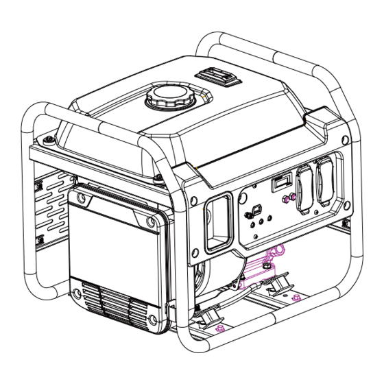
Page 28: Parts Diagram
SPECIFICATIONS Parts Diagram 28 27... -
Page 29: Parts List
SPECIFICATIONS Parts List Item Description Item Description Bolt M6x16 Nut M5 Starting guard circle Cover, Inverter Inverter Support, Air Filter Grounding Wire Inner Cover, Inverter rubber sleeve Washer Engine Nut M6 Insulation Board Clip, Fuel Line Foot air pipe Clip, Fuel Line Frame Fuel Valve Choke... -
Page 30: Engine Parts Diagram
SPECIFICATIONS Engine Parts Diagram... -
Page 31: Engine Parts List
SPECIFICATIONS Engine Parts List Item Description Item Description Dipstick alternator stator Crankcase covrer seal washer Coil assy, ignition Dowel pin fix pin Oil plug Cover comp, pan Shroud Rubber stopper Cover, recoil starter Crankcase Crankcase cover Choke assembly Cylinder head seal washer hexagon socket head cap screws Cylinder cover seal washer alternator rotor... -
Page 32: Wiring Diagram
SPECIFICATIONS Wiring Diagram... -
Page 33: Troubleshooting
TROUBLESHOOTING Problem Cause Solution No fuel Add fuel Generator will not start Faulty spark plug Replace spark plug Unit loaded during start up Remove load from unit Fill crankcase to the proper level Low oil level Place generator on a at, level surface Generator will not start;... - Page 36 DO NOT RETURN TO STORE - CALL CUSTOMER SERVICE.
- Page 37 WARRANTY REGISTRATION FORM Register your product by mailing this form to support@a-ipower.com or register online at www.a-ipower.com. Registering your product is important, it provides protection: 1) You have record of product purchased. 2) Customer Service can Better serve you for Warranty related issues. 3) We can contact you in the unlikely event should notification is necessary.
- Page 40 Fontana, CA 92337 USA Phone: 1-855-888-3598 support@a-ipower.com www.a-ipower.com MADE IN CHINA 32082-03051-00...
Need help?
Do you have a question about the AT21-132001 and is the answer not in the manual?
Questions and answers