ITech IT-M7700 Series User Manual
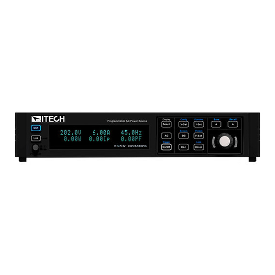
Programmable ac power source
Hide thumbs
Also See for IT-M7700 Series:
- Programming manual (102 pages) ,
- Programming manual (119 pages) ,
- Programming manual (126 pages)

Subscribe to Our Youtube Channel
Related Manuals for ITech IT-M7700 Series


Summary of Contents for ITech IT-M7700 Series
- Page 1 Programmable AC Power Source IT-M7700 Series User Manual Model: IT-M7700 Series Version: V1.9/4,2023...
- Page 2 CAUTION sign until the in- pose. ITECH shall not be held liable Manual Part Number dicated conditions are for errors or for incidental or indirect fully understood and met.
-
Page 3: Warranty
Warranty ITECH warrants that the product will be free from defects in material and work- manship under normal use for a period of one (1) year from the date of delivery (except those described in the Limitation of Warranty below). -
Page 4: Safety Symbols
Failure to comply with these precautions or specific warn- ings elsewhere in this manual will constitute a default under safety standards of design, manufacture and intended use of the instrument. ITECH assumes no li- ability for the customer’s failure to comply with these precautions. - Page 5 This instrument is used for industrial purposes, do not apply this product to IT power supply system. • Never use the instrument with a life-support system or any other equipment subject to safety requirements. Copyright © Itech Electronic Co., Ltd.
-
Page 6: Environmental Conditions
Make sure the vent hole is always unblocked. Environmental Conditions The instrument is designed for indoor use and an area with low condensation. The table below shows the general environmental requirements for the instrument. Copyright © Itech Electronic Co., Ltd. -
Page 7: Regulation Tag
The service life of the product is 10 years. The product can be used safely within the environmental protection period; oth- erwise, the product should be put into the recycling system. Copyright © Itech Electronic Co., Ltd. -
Page 8: Waste Electrical And Electronic Equipment (Weee) Directive
According to the equipment classifi- cation in Annex I of the WEEE direc- tive, this instrument belongs to the “Monitoring” product. If you want to return the unnecessary instrument, please contact the near- est sales office of ITECH. Copyright © Itech Electronic Co., Ltd. -
Page 9: Compliance Information
2. Connection of the instrument to a test object may produce radiations beyond the specified limit. 3. Use high-performance shielded interface cable to ensure conformity with the EMC standards listed above. Safety Standard IEC 61010-1:2010+A1:2016 Copyright © Itech Electronic Co., Ltd. -
Page 10: Table Of Contents
4.8 Executing Measurement ..................57 4.8.1 Measurement Functions................58 4.9 Function Operation ....................59 4.9.1 Function Menu at a Glance ................. 59 4.9.2 List Function ....................62 4.9.3 Dimmer Function ..................64 4.9.4 Surge/Trap Function..................65 Copyright © Itech Electronic Co., Ltd. VIII... - Page 11 6 Routine Maintenance ..................... 106 6.1 Instrument Self-Test..................... 106 6.2 Cleaning and Maintenance .................. 106 6.3 Prompt Information Reference................107 6.4 Contact of ITECH Engineers ................108 6.5 Return for Repair....................110 7 Technical Specification ....................111 7.1 IT-M7721......................111 7.2 IT-M7721L......................
-
Page 12: Quick Reference
♦ System Menu at a Glance ♦ Optional Accessories 1.1 Brief Introduction ITECH newly-launched IT-M7700 High Performance Programmable AC Power Supply combines intelligence and flexibility, breaks through the huge defects of the traditional AC power source, reduces the size to only 1⁄2 1U, maximizes space utilization. -
Page 13: Front Panel At A Glance
USB_VCP, external analog, IO. Flexible and cost effective *1 IT-M7721L/IT-M7722L do not support this function. *2 Realize by PC software. *3 Available on IT-M7721/7722/7722D/7722E/7723D/7723E. *4 Only available for the model IT-M7722D,IT-M7723D. Model Selection Table for IT-M7700 Series: Power(AC/DC) Voltage Frequency Height... - Page 14 [Shift] + [Link] (Local) keys to switch the instru- ment to local control mode. Power switch Turns the instrument on or off. Vacuum fluo- Displays all instrument functions. The information rescent display changes based on selected function. Copyright © Itech Electronic Co., Ltd.
-
Page 15: Front Panel Keys At A Glance
The (.) key is the decimal point. • The ± key is used to enter a positive or negative signs. 1.3 Front Panel Keys at a Glance The keys introduction of IT-M7700 series power source is shown as follows. • IT-M7721/IT-M7722/IT-M7721L/IT-M7722L/IT-M7722D/IT-M7723D/IT- M7722E/IT-M7723E keys •... - Page 16 Selects the menu item or confirm an operation. [0]-[9] Numeric keys. +/– Positive and negative signs. Decimal point. The left and right navigation keys are used to adjust the cursor to the specified position or scrolls pages to view menu items. Copyright © Itech Electronic Co., Ltd.
-
Page 17: Rear Panel At A Glance
(Save) Returns the instrument to the specified setup. [Shift]+ (Recall) 1.4 Rear Panel at a Glance The rear panel of this series instruments is shown below. • IT-M7721/IT-M7722/IT-M7721L/IT-M7722L/IT-M7722D rear panel • IT-M7723 rear panel Copyright © Itech Electronic Co., Ltd. - Page 18 Therefore, they cannot be connected to the DUT, which are only used for short circuit during local measurement. • I/O function, please refer to 4.9.5 Digital I/O Function. Copyright © Itech Electronic Co., Ltd.
-
Page 19: Front Panel Display At A Glance
100 V to 240 V. 1.5 Front Panel Display at a Glance The IT-M7700 series power supply has different display information under the AC mode and the DC mode. Details are as follows. • Under the AC mode, the AC main interface 1 is displayed as follows:... - Page 20 Displays the Meter value of the apparent power. vTHD meter value Displays the Meter value of the total voltage harmonic distortion. iTHD meter value Displays the Meter value of the total current harmonic distortion. Copyright © Itech Electronic Co., Ltd.
-
Page 21: Configuration Menu At A Glance
At this time, the screen displays the optional menu. Click Rotary to page up or page down the menu. Press the [Enter] key to enter into the se- lected menu item. Press the [Esc] key to exit the menu function. Copyright © Itech Electronic Co., Ltd. - Page 22 30 sets of built-in waveforms. USER1~USER5 5 sets of user-defined waveforms. Set the instruments to 3-phase or series operation mode. Parallel Set the instrument to single mode, Single i.e., disable the 3-phase or series operation mode. Copyright © Itech Electronic Co., Ltd.
- Page 23 AC Mode) Set the voltage rising time. (only displayed under the DC V-Rise Time Mode) Set the output waveform type. (only displayed under the AC Wave Mode) Sine Sinusoidal Square Square Triangle Triangle Copyright © Itech Electronic Co., Ltd.
-
Page 24: System Menu At A Glance
I/O Config face is dynamically displayed based on different interface cards. No optional communication interfaces. NULL When the expansion slot is inserted into the IT- GPIB E1205, you can select the GPIB communication interface. Copyright © Itech Electronic Co., Ltd. - Page 25 The following information only appear when Manu is Manu selected. • IP: IP address • Gate: Default gateway • Mask: Subnet mask Copyright © Itech Electronic Co., Ltd.
- Page 26 Viewing active LAN settings. Info LAN Status MAC Address IP Address Gateway Address Submask Address DHCP Server Address DNS Server Address Domain Name Host Name Description Select whether to reset the LAN setting or not. Reset Copyright © Itech Electronic Co., Ltd.
- Page 27 On or Off will not affect the operation of relay. System Select whether to restore the factory default settings or not. Reset Don’t restore the factory default settings. Restore the factory default settings. System View the system information. Info Display the manufacturer. Manufacturer Copyright © Itech Electronic Co., Ltd.
-
Page 28: Optional Accessories
• Cabinet installation The IT-M7700 series instruments can be mounted on a standard 19-inch cabinet. ITECH has prepared a special bracket for the user as a mounting kit. The detailed descriptions of the options are as follows. The following optional accessories from ITECH are sold separately. Users need to purchase separately. - Page 29 USB communica- IT-E1209 When the user needs to use USB interface tion interface to enable remote operation, this option is the right choice. Copyright © Itech Electronic Co., Ltd.
- Page 30 User Manual 》for detailed description about the installation method. Hot swap is not available for the communication card and analog card. After changing the communication card and analog card, you must re-start the instrument. Copyright © Itech Electronic Co., Ltd.
-
Page 31: Inspection And Installation
Ex-Factory It is the test report of the instrument be- Test Report fore delivery. Copyright © Itech Electronic Co., Ltd. -
Page 32: Instrument Size Introduction
2.2 Instrument Size Introduction The instrument should be installed at well-ventilated and rational-sized space. Please select appropriate space for installation based on the instrument size. The detailed dimension drawings of the IT-M7700 series are as follows: IT-M7721/IT-M7722/IT-M7721L/IT-M7722L/IT-M7722D Copyright © Itech Electronic Co., Ltd. - Page 33 Inspection and Installation IT-M7723 Copyright © Itech Electronic Co., Ltd.
-
Page 34: Connecting The Power Cord
Inspection and Installation IT-M7723D/IT-M7722E/ IT-M7723E 2.3 Connecting the Power Cord Precautions To prevent electric shock and damage to the instrument, observe the following precautions. Copyright © Itech Electronic Co., Ltd. - Page 35 AC Power Input Level Working voltage for IT-M7700 series power is 100 ~ 240V, AC power input level: 100 ~ 240V, 50 ~ 60Hz. Power Cord Type and Connecting Method IT-M7700 series contains many models.
- Page 36 2. Connect the female end of the supplied line cord to the AC receptacle on the rear panel. 3. Connect the plug of the power cord to a grounded AC outlet. • IT-M7723/IT-M7723D/IT-M7722E/IT-M7723E power supply provides the standard power cords as below. Connecting Method: Copyright © Itech Electronic Co., Ltd.
-
Page 37: Connecting The Device Under Test (Dut)
• Remote sensing:The voltage sensed by the instrument is the voltage at the terminal of the remote object under test. Precautions To prevent electric shock and damage to the instrument, observe the following precautions. Copyright © Itech Electronic Co., Ltd. - Page 38 Connecting the DUT (Local Measurement) The connection diagram and steps of local sensing are as follows: 1. Before connecting the DUT, be sure that the instrument Power is in Off position. Copyright © Itech Electronic Co., Ltd.
- Page 39 2. Remove the cover of output terminal and remote sense terminal. 3. Disconnect the wires/short clips between SL+ and L+, SN- and N-. 4. Use armored twisted-pair cables to connect the remote sense terminals and the device under test. Copyright © Itech Electronic Co., Ltd.
-
Page 40: Connecting The Interface
2.5 Connecting the Interface The IT-M7700 series power supply has no standard-equipped interfaces card. Users can purchase interface cards separately. Users can choose one of RS- 232, RS-485, USB, GPIB, LAN, CAN to communicate with the computer. For details, see 1.8 Optional Accessories... -
Page 41: Usb Interface
USB interfaces (each end). 2. Press the composite keys [Shift] + [DC](System) to enter into the system menu interface. 3. Rotate the knob to select I/O Config and press [Enter] key to confirm. Copyright © Itech Electronic Co., Ltd. -
Page 42: Gpib Interface
VCP: USB_VCP virtual serial port. When the host software uses the USBVCP for communication(The WIN7/XP system needs to be installed with IT-7722-VCP.inf. Download from the ITECH website or contact ITECH agent), this USB is the USB_VCP interface. 5. Press [Esc] to exit the system menu setting. - Page 43 When the instrument and computer are connected to the router, an independent IP address must be assigned for the instrument. LAN Status Indicator The lower icon notes the two status LEDs located at the bottom of the LAN port. Copyright © Itech Electronic Co., Ltd.
- Page 44 IP Address. When a client IP address is on a different subnet, all packets must be sent to the Default Gateway. – DNS1: This field enters the primary address of the server. Contact your LAN administrator for server details. The same numbering notation Copyright © Itech Electronic Co., Ltd.
- Page 45 4. Rotate the knob to select I/O Advance Config and press [Enter] to enter the LAN advanced setting interface. 5. Rotate the knob to select LAN Reset and press [Enter] key to reset the LAN parameter configuration. • NO: indicates refuse to reset the LAN setting. Copyright © Itech Electronic Co., Ltd.
- Page 46 On: indicates enable the service. • Off: indicates disable the service. 8. When enabling the Raw Socket service, the user needs to set the corre- sponding Port. 9. After setting, press [Esc] to exit. Copyright © Itech Electronic Co., Ltd.
- Page 47 The detailed descriptions are as follows. • Home: Http home interface, displays the model and appearance of the instrument. • Information: Displays the serial number of the instrument and more system information as well as LAN configuration parameters. Copyright © Itech Electronic Co., Ltd.
-
Page 48: Interface
LAN Configuration: Reconfigure the LAN parameters. • Security: Change the password and control access to the Http interface. • Manual: Go to the ITECH official website and view or download the relevant documents. • Logout: Logout the Http interface. 2.5.3.2 Using Telnet The Telnet utility (as well as sockets), is another way to communicate with the instrument without using I/O libraries or drivers. - Page 49 Directly connected to the computer, as shown below: RS–232 Configuration The user needs to configure the RS–232 interface parameters in the system menu before using the remote control. The RS–232 interface parameters are as follows. Copyright © Itech Electronic Co., Ltd.
-
Page 50: Can Interface
The following figure shows the CAN interface system. The user can select the CAN interface converter to connect to your computer according to the actual sit- uation. Take the CAN to USB interface device as an example. Copyright © Itech Electronic Co., Ltd. - Page 51 4. Rotate the knob to select I/O Advance Config and press [Enter] key to en- ter the CAN Advancing Setting interface. 5. Rotate the knob to select Can Address and press [Enter] key. After setting the communication address, press [Enter] key to confirm. Copyright © Itech Electronic Co., Ltd.
-
Page 52: Interface
Definition of RS-485 Pins RS-485 interface pins are integrated in the DB25 analog interface. Pin25 and to4.12.1 模拟量接口引脚定义 Pin13 are the A and B pins for RS-485. Refer more information. Copyright © Itech Electronic Co., Ltd. - Page 53 6. Rotate the knob to select 485 Address and press [Enter] key to confirm. Use left and right keys or rotate the knob to set the communication address, and press [Enter] key to confirm. 7. Press [Esc] to exit the system menu setting. Copyright © Itech Electronic Co., Ltd.
-
Page 54: Getting Started
The power switch is located in the lower left corner of the front panel. See Front Panel at a Glance for details. The power switch is a push button. Press the button once to turn the instrument on and press it again to turn the instru- ment off. Copyright © Itech Electronic Co., Ltd. - Page 55 Wait until the power is turned off and then start again. If the problem still cannot be solved after restart- ing, please contact the ITECH engineer. Please refer to Error information list detailed information about common error messages.
-
Page 56: Applying Dc Output
5. Checking the Meter values of voltage, current, and power. After the Output is enabled, the instrument will continuously measure and display the Meter values of voltage, current, and power on the front panel. Copyright © Itech Electronic Co., Ltd. -
Page 57: Applying Waveform Output
Press the composite keys [Shift]+[V-set](Config) to enter into the config- uration menu interface. 1:I Range = High 2:AC + DC = b. Rotate the knob to select On Phase and press [Enter] key to confirm. 3:On Phase = 0.0° 4:Off Phase = 0.0° Copyright © Itech Electronic Co., Ltd. - Page 58 Press [On/Off] key to enable the instrument output. When the Output is in On status, the Output [On/Off] key will light up; when the Output is in Off sta- tus, the Output [On/Off] will light off. 8. Check the Meter value of the instrument. Copyright © Itech Electronic Co., Ltd.
- Page 59 10.03V 0.0005A 50.0Hz 0.00W 0.0056Ip 1.00PF Press the [Select] key to switch the display of Meter value. 10.03V 0.0005A 0.00W 0.0VA vTHD=1.02 IT-M7721L/IT-M7722L does not support displaying vTHD and iTHD. Copyright © Itech Electronic Co., Ltd.
-
Page 60: Operation And Application
♦ System-Related Operations ♦ External Analog Quantity Function (Option) 4.1 Select the Output Mode The IT-M7700 series power supply has 3 output modes: AC, DC and AC+DC. The User should set specific output mode based on required applications. AC Mode... -
Page 61: Setting The Voltage Output Range
Model Voltage range Output range IT-M7723 High Voltage output range: • AC: 0~600V • DC: 0~±800V Current output range: • AC: 0~6A • DC: 0~±6A Voltage output range: • AC: 0~300V • DC: 0~±400V Copyright © Itech Electronic Co., Ltd. -
Page 62: Set The Ac Output
[V-set] key will light up. 50.0V 6.00A 60.0Hz 0.00W 0.00Ip 0.00PF 3. Rotate the knob clockwise to increase the voltage setting value and anti- clockwise to decrease the value. Set the required value. Copyright © Itech Electronic Co., Ltd. -
Page 63: Set The Ac Frequency
Press [Esc] key to exit the input mode. 4.3.3 Set the AC Phase Angle IT-M7700 series supports the initial phase and stop phase of the output wave- form settable to meet different test requirements. The initial phase and stop phase are set in the range of 0.0°~359.9°. By adjusting the phase angle, the user can test the rush current of the product at different positions which is widely applied to various switch current impulse tests and various rectifiers test. -
Page 64: Select The Output Waveform
Press [Enter] key to confirm. 5. Press [Esc] to exit the configuration menu setting. • The user-defined waveforms need to be defined in and downloaded from the re- mote PC. Refer to the IT-M7700 Series Software User Manual for operation methods. • Refer to A.2 Built -in Waveforms... -
Page 65: Set The Dc Output
You can set the voltage rise time on the front panel or through remote control operation. The set voltage rise time will affect the voltage change speed when the real-time voltage changes. The setting steps are as follows: Copyright © Itech Electronic Co., Ltd. -
Page 66: Set The Over-Current Protection Point
Rotate the knob to change the digit value. 3. Press [Enter] key to confirm the OCPrms setting value. Press [Esc] key to exit the input mode. Copyright © Itech Electronic Co., Ltd. -
Page 67: Turning The Output On And Off
4. Turn the knob to change the output value, and the output waveform value re- mains constant. After pressing [Enter] to confirm, the output voltage value will change with the input value. The output waveform is shown in the figure below. Copyright © Itech Electronic Co., Ltd. -
Page 68: Executing Measurement
Output is On, it will measure the V, I, F, and P of the output ter- minal of the power supply. Before executing measurement, the user needs to set the current measurement range. Copyright © Itech Electronic Co., Ltd. -
Page 69: Measurement Functions
Total voltage harmonic distortion factor. iTHD Total current harmonic distortion factor. DC Mode It is the measurement of DC Voltage. It is the measurement of DC Current. Power. IT-M7721L/IT-M7722L does not support displaying vTHD and iTHD. Copyright © Itech Electronic Co., Ltd. -
Page 70: Function Operation
Turn the surge/trap function off. Turn the surge/trap function on. Period Set the period of the surge/trap. Width Set the surge/trap width. Percent Set the percentage of the surge/ trap amplitude to AC signal amplitude (rms). Copyright © Itech Electronic Co., Ltd. - Page 71 When send 0V signal to IO2, the instrument turns off the output. Off Timer Set the output timer function. Turn the output timer off. Turn the output timer on. Copyright © Itech Electronic Co., Ltd.
- Page 72 Config IO1 as output pin. L if out on When the output state of the instru- ment is On, this pin outputs 0V. When the output state of the instru- ment is Off, this pin outputs 5V. Copyright © Itech Electronic Co., Ltd.
-
Page 73: List Function
This power supply needs to use the IT-M7700 Series Software to edit the List function contents, and download the List files to local equipment. Then, the in- strument can locally run the List function. - Page 74 When List Trigger = On, press the Trigger key once, and the instrument will run one step of List output. • When List Trigger = Off, the instrument will output based on defined List. IT-M7721L/IT-M7722L do not support list function. Copyright © Itech Electronic Co., Ltd.
-
Page 75: Dimmer Function
The Dimmer Function aims to adjust the light illuminance intensity by setting the phase angle and concealing the leading edge or trailing edge waveform. This IT-M7700 series power supply supports front and rear phase angle dimmer or speed adjustment test to verify whether the product has potential quality prob- lem when the end user uses dimmer or the speed controller. -
Page 76: Surge/Trap Function
Percent tude (rms). Operation Steps: 1. Press the [AC] key to set the instrument to AC output mode. 2. Refer to 4.3 Set the AC Output to set parameters related to basic Sine waveform. Copyright © Itech Electronic Co., Ltd. - Page 77 Press[On/Off] again to stop output. 10.0V 3.00A 50.0Hz 1Cycle 1.00mS 30.0% Waveform Example • The trap diagram when Period=2Cycle, Width=1.00mS, and Percent=30% is as follows: • The surge diagram when Period=1Cycle, Width=0.4mS, and Percent=200% is as follows: Copyright © Itech Electronic Co., Ltd.
-
Page 78: Digital I/O Function
The surge/trap function can only be used under the AC Mode. • IT-M7721L/IT-M7722L do not support surge/trap function. 4.9.5 Digital I/O Function The IT-M7700 series power supply supports digital I/O function, which can be used for controlling and monitoring power supply output. For position, see Rear Panel at a Glance. - Page 79 When send 5V signal to IO1, the instrument turns off the output. H To out on When send 5V signal to IO1, the instru- ment turns on the output. When send 0V Copyright © Itech Electronic Co., Ltd.
- Page 80 Rotate the knob to select Input and press [Enter] key to config IO2 as in- put pin. d. Rotate the knob to select L To out on or H To out on and press [Enter] key to confirm. Copyright © Itech Electronic Co., Ltd.
- Page 81 5V. When the output state of the instrument is Off, this pin outputs 0V. 2. You can connect a digital voltmeter to IO1 and GND to monitor the On/Off status of the instrument. Copyright © Itech Electronic Co., Ltd.
-
Page 82: Set The Output Timer Function
The OVP (rms) function is always enabled. Set the OVP(rms) point 1. Press the composite keys [Shift] + [F-set](Protect) to enter Protect menu interface. 2. Rotate the knob to select OVP(rms) and press [Enter] key to confirm. Copyright © Itech Electronic Co., Ltd. -
Page 83: Set The Over-Voltage Protection (Peak)
When over-voltage protection occurs, the instrument responds as follows: • The instrument output is turned off, and other keys (except the [Esc] key) are locked. • The buzzer sounds intermittently three times: one long beep and two short beeps. Copyright © Itech Electronic Co., Ltd. -
Page 84: Set The Under-Voltage Protection (Rms)
UVP(rms) status. 4.10.4 Set the Over-Current Protection (rms) The user can set the over-current protection point for the over-current protection (rms) function. When the output current reaches the over-current protection Copyright © Itech Electronic Co., Ltd. - Page 85 Press [Esc] key (or send the command PROTect:CLEar) to clear the protection status. The “OCPrms Occurred!!” dis- played in front panel is cleared and the instrument exits OCP status. Copyright © Itech Electronic Co., Ltd.
-
Page 86: Set The Over-Current Protection (Peak)
The instrument output is turned off, and other keys (except the [Esc] key) are locked. • The buzzer sounds intermittently three times: one long beep and two short beeps. • The interface displays “OCPpeak Occurred!!”; • Status register, the OCPpeak status bit is set to 1. Copyright © Itech Electronic Co., Ltd. -
Page 87: Set The Over-Power Protection
If the output current reaches the limiting current protection point, the pro- tection will be activated. The power supply output current is controlled within the current limiting value, and the output is stopped after several milliseconds. The Copyright © Itech Electronic Co., Ltd. -
Page 88: Set The Sense Check Protection
4. Press [Esc] to exit the protection menu setting. Clear protection status When protection occurs, the instrument responds as follows: • The instrument output is turned off, and other keys (except the [Esc] key) are locked. Copyright © Itech Electronic Co., Ltd. -
Page 89: Limiting The Setting Value Range
• OCP-Min: set the minimum value of the OCPrms setting value. 4. Rotate the knob to adjust the parameter, and press [Enter] key to confirm. 5. Press [Esc] to exit the protection menu setting. Copyright © Itech Electronic Co., Ltd. -
Page 90: System-Related Operations
4.11.2 Save and Recall Operations IT-M7700 series power source can save up to 10 common parameters in nonvo- latile memory (No. 0 to No. 9) for user to recall conveniently. The contents stored in each group include: output mode(AC/DC), voltage setting value(AC), voltage setting value(DC), OCPrms, frequency setting value and phase angle. -
Page 91: Key Lock Function
OCPrms and frequency setting value. • The output state of the power source, i.e., the [On/Off] key state. Operation Steps: 1. Press the composite keys [Shift] + [DC](System) to enter into the system menu interface. Copyright © Itech Electronic Co., Ltd. -
Page 92: Restore The As-Shipped Settings
[Enter] key to confirm. • No: default value, indicates the power source cancels this menu setting. • Yes: indicates the power source restores the as-shipped settings. 4. Press [Esc] to exit the system menu setting. Copyright © Itech Electronic Co., Ltd. - Page 93 0.0° Off Phase 0.0° V-Rise Time Wave Sine (IT-M7721L/IT-M7722L does not support this function.) Parallel Single(Only IT-M7721/IT-M7722/IT-M7722D/ IT-M7723D/IT-M7722E/IT-M7723E support this function.) System menu Beep PowerOn Last+Off Relay Ctrl Out Syn System Reset Protect menu Copyright © Itech Electronic Co., Ltd.
- Page 94 • IT-M7721/IT-M7722/IT-M7722D: 20A • IT-M7723(V Range = High): 20A • IT-M7723(V Range = Low): 40A OCP(peak) • IT-M7723D/IT-M7722E/IT-M7723E: 50A OCP delay 50ms • IT-M7721L/IT-M7721/IT-M7722D: 300VA • IT-M7722L/IT-M7722: 600VA • IT-M7723: 1200VA • IT-M7723D: 750VA Copyright © Itech Electronic Co., Ltd.
- Page 95 IT-M7723(V Range = High): - 800V • IT-M7723(V Range = lOW): - 400V • IT-M7723D/IT-M7722E/IT-M7723E: - Vdc-Min 400V • IT-M7721L/IT-M7722L: 100Hz • IT-M7721/IT-M7722/IT-M7722D: 1000Hz • IT-M7723/IT-M7723D: 1000Hz Freq-Max • IT-M7722E/IT-M7723E: 1000Hz Freq-Min 45.0Hz • OCP-Max IT-M7721L/IT-M7721/IT-M7722D: 3.15A Copyright © Itech Electronic Co., Ltd.
-
Page 96: View The System Information
3. Rotate the knob to page up and down and check the instrument system in- formation. Specific parameters are shown in the table below: Name Description Manufacturer Display the manufacturer's name. Model Display the instrument model. Version Display the software version. Serial Number Display the serial number. Copyright © Itech Electronic Co., Ltd. -
Page 97: Set The Relay Control
• NC: The relay is normally closed. Whether the instrument out is On or Off will not affect the operation of relay. 4. Press [Esc] to exit the system menu setting. Copyright © Itech Electronic Co., Ltd. -
Page 98: External Analog Quantity Function (Option)
For safety reasons, when the DUT is other types of loads, you need to select the Out Syn option. 4.12 External Analog Quantity Function (Option) IT-M7700 series power supply provides a optional DB25 analog interface(IT- E1208). The analog interface provides the following capability: •... - Page 99 Analog out The -10Vdc/10mA reference volt- age output by the power supply can be connected to a resistance subdi- vision for analog control. Error Clear Digital in Signal input for clearing the instru- ment error. Copyright © Itech Electronic Co., Ltd.
-
Page 100: Enable/Disable Analog Control
2. Correctly connect the Pin 1 (OCPrms Program) and Pin 15 (Vac/Vdc Pro- gram): Connect an external DC voltage source capable of outputting 0V ~ 10V voltage between Pin 1 and Pin 3 and between Pin 15 and Pin 4 Copyright © Itech Electronic Co., Ltd. -
Page 101: Analog Quantity Control
2. Select the slope of the trigger signal: rising time or falling time. a. Press the composite keys [Shift] + [DC](System) to enter into the system menu interface. b. Rotate the knob to select I/O Advance Config and press [Enter] key to confirm. Copyright © Itech Electronic Co., Ltd. - Page 102 – Voltage setting: Analog control of the output voltage can be accom- plished by connecting external DC voltage sources in the range of 0 V to 10 V to the 15 and 4 pins. Copyright © Itech Electronic Co., Ltd.
- Page 103 This function can monitor and read the output voltage and current values. The connection diagram is as follows: • Current monitoring: Output voltage values can be monitored and read by connecting a digital voltmeter to the 14 and 6 pins. Copyright © Itech Electronic Co., Ltd.
- Page 104 Pin 9 will output 5V; if the instrument is in unloaded status, Pin 9 will output 0V. • Monitor the instrument On/Off status: When the instrument is On, Pin 23 will output 5V; when the instrument is Off, Pin 23 will output 0V. Copyright © Itech Electronic Co., Ltd.
-
Page 105: Calibrate External Voltage Control
1. Please refer to the figure below for connection of the instrument under calibration. By connecting a digital voltmeter to the 15, 16 and 6 pins. 2. Enter calibration mode. a. Press the composite keys [Shift] + [DC](System) to enter into the system menu interface. Copyright © Itech Electronic Co., Ltd. - Page 106 On “PT 2” input the voltage value which is the second point showed on the Voltage Meter, and press [Enter] key to confirm. ISET 9.000V DA: 3456 PT 2 AD:28500 M 9.070V Finish the external current calibration. Copyright © Itech Electronic Co., Ltd.
-
Page 107: Multi-Units Operation
This chapter takes two IT-M7721 power supply as an example to describe how to series the single units and how to return from series mode to single mode. Operation steps 1. Connect the instruments according to the following diagram. • Local sense Copyright © Itech Electronic Co., Ltd. - Page 108 A and slave B will light up one after another. Press the [Link] key on the front panel of the master A again to cancel the synchroni- zation, and the [Link] lights of both power supplies will lights off. 4. Set the series output. Copyright © Itech Electronic Co., Ltd.
- Page 109 Set the current measurement range. 3:On Phase Set the starting phase angle of the waveform. 4:Off Phase Set the ending phase angle of the waveform. System System function 5:Relay Ctrl Set the relay control. Copyright © Itech Electronic Co., Ltd.
-
Page 110: Three-Phase Operation
IT-M7721 power supply as an example to describe how to realize 3-phase in a single units and how to return from 3-phase mode to single mode. Operation steps 1. Connect the instruments according to the following diagram. • Local sense Copyright © Itech Electronic Co., Ltd. - Page 111 Multi-units operation • Remote sense Copyright © Itech Electronic Co., Ltd.
- Page 112 [V-set] Sets the output voltage value. OCPrms [I-set] Sets the OCPrms value. Freq [F-set] Sets the frequency value. On or Off [On/Off] Turns the instrument output on or off. Protect Protection function Copyright © Itech Electronic Co., Ltd.
- Page 113 M7700 Programming and Grammar Guide". Revert to single mode 1. Press the [Link] key on the front panel of master A to cancel the three-phase synchronization mode. 2. Set each of the three instruments to single mode. Copyright © Itech Electronic Co., Ltd.
-
Page 114: Multi-Channel Function
“Chan Number Conflict”. In this case, rotate the knob to change the channel number directly, press [Enter] to confirm. The following three instruments are taken as an example to describe the connection and operation steps of multiple channels. Copyright © Itech Electronic Co., Ltd. - Page 115 Connect system bus interfaces. b. Connect the DUTs. Refer to 2.4 Connecting the Device Under Test (DUT) for more information about connection methods. c. Connect the instrument to PC. refer to 2.5 Connecting the Interface. Copyright © Itech Electronic Co., Ltd.
- Page 116 Multi-units operation 3. Through the PC software, send SCPI commands to control the specified instrument or all instruments on the line. For details, see the content of the multi-channel command chapter of "IT-M7700 Programming Guide". Copyright © Itech Electronic Co., Ltd.
-
Page 117: Routine Maintenance
Routine Maintenance Routine Maintenance This chapter describes general maintenance items and maintenance methods of the IT-M7700 series power source. ♦ Instrument Self-Test ♦ Cleaning and Maintenance ♦ Prompt Information Reference ♦ Contact of ITECH Engineers ♦ Return for Repair 6.1 Instrument Self-Test Self-test checks that the minimum set of logic and power mesh systems are functioning properly. -
Page 118: Prompt Information Reference
Routine Maintenance 6.3 Prompt Information Reference The IT-M7700 series power supply has a detailed error and prompt information function, so as to help the user to easily carry out positioning and measurement during measurement and use. This section describes all error information of the IT-M7700 series power supply as well as disposals. -
Page 119: Contact Of Itech Engineers
This section describes operations to be carried out by the user in case of failure of the instrument. Preparation before contact When the instrument fails, you should make the following preparations before returning the instrument to ITECH for repair or contacting engineers. Copyright © Itech Electronic Co., Ltd. - Page 120 Collect the SN number ITECH will constantly improve the product performance, availability and reliabil- ity. The service personnel of ITECH will record changes of each instrument. All relevant information is marked uniquely according to the serial number of each instrument. The equipment returned for repair must adopt the SN number as the tracking ID.
-
Page 121: Return For Repair
4006-025-000 for technical support and services. 6.5 Return for Repair If your instrument fails during the warranty period, ITECH will repair or replace it under the terms of your warranty. After your warranty expires, ITECH offers re- pair services at competitive prices. Also you can purchase an extended mainte- nance service contract that exceeds the standard warranty period. -
Page 122: Technical Specification
Technical Specification Technical Specification This chapter will introduce the rated voltage, current, power and many other main parameters of IT-M7700 series power source. ♦ IT-M7721 ♦ IT-M7721L ♦ IT-M7722 ♦ IT-M7722D ♦ IT-M7722E ♦ IT-M7722L ♦ IT-M7723 ♦ IT-M7723D ♦ IT-M7723E 7.1 IT-M7721... - Page 123 High range) Accuracy ±(0.5%+0.5% F.S.) Range 0.1~1250 mA AC current (rms, low range at Resolution 0.1mA 100HZ) Accuracy ±(0.25%+0.25% F.S.) Range 0~4.25A AC current (peak) Resolution 10mA Accuracy ±(0.4%+0.8% F.S.) DC voltage Accuracy ±(0.25%+0.25% F.S.) Copyright © Itech Electronic Co., Ltd.
-
Page 124: M7721L
*4: This specification is applicable below ≤800Hz. *5: The applicable range of frequency resolution is 45~99.9Hz. 7.2 IT-M7721L Parameter IT-M7721L AC Input Voltage 100 ~ 240Vac Single-phase Phase Frequency 47 ~ 63Hz Max.current 4.3A 0.99 (Typical) Power factor AC Output Copyright © Itech Electronic Co., Ltd. - Page 125 DC voltage Accuracy ±(0.2%+0.2% F.S.) Dynamic response time (Full load of ≤0.5ms 10~90%) Meter Range 0-300V AC Voltage Resolution 0.1V Accuracy ±(0.25%+0.25% F.S.) Range 0.1 ~ 3A AC current (rms) Resolution 10mA Accuracy ±(0.5%+0.5% F.S.) Copyright © Itech Electronic Co., Ltd.
-
Page 126: M7722
*3: Tested with pure resistive load. *4: The applicable range of frequency resolution is 45~99.9Hz. 7.3 IT-M7722 Parameter IT-M7722 AC Input Voltage 100~240Vac Single-phase Phase Frequency 47~63Hz Max.current 8.5A 0.99 (Typical) Power factor AC Output Copyright © Itech Electronic Co., Ltd. - Page 127 Max. output power 600W Max. output voltage ±400Vdc Maximum output current (rms) ±6A DC voltage Accuracy ±(0.2%+0.2% F.S.) Dynamic response time (Full load of ≤0.5ms 10~90%) Meter Range 0~300V AC Voltage Resolution 0.1V Accuracy ±(0.25%+0.25% F.S.) Copyright © Itech Electronic Co., Ltd.
- Page 128 *1: Min voltage for THD test is 100Vac. *2: Min voltage for frequency display accuracy is 100Vac. *3: Tested with pure resistive load. *4: This specification is applicable below ≤800Hz. *5: The applicable range of frequency resolution is 45~99.9Hz. Copyright © Itech Electronic Co., Ltd.
-
Page 129: M7722D
Resolution 0.1V Output voltage (VAC) Accuracy ±(0.2%+0.2% F.S.) Resolution 0.1Hz Frequency Accuracy ±0.1% Resolution 0.1° Phase angle degree range Accuracy 0.5° DC offset value 20mVdc Efficiency 75% (Typical) DC Output Max. output power 300W Copyright © Itech Electronic Co., Ltd. - Page 130 Accuracy ±(0.25%+0.355% F.S.) range) DC current (Low Accuracy ±(0.25%+0.355% F.S.) range) Range 45~1000Hz Frequency Resolution *5 0.1Hz Accuracy *2 ±0.1% Resolution 100mVA Power *4 (S) Accuracy ±(0.5%+0.5% F.S.) Other OTP, OCP, OVP, OPP Protection Copyright © Itech Electronic Co., Ltd.
-
Page 131: M7722E
Max. output power 1000VA Max. output voltage 300V Output phase Single-phase Current range(rms) Current range(peak) Output frequency range 45~1000Hz Phase angle degree range 0~359.9° ≤0.3% at 45~100Hz ≤1% at 101~800Hz THD*1*3 ≤ (0.15%f-0.2)% at 801~1000Hz Copyright © Itech Electronic Co., Ltd. - Page 132 High range) Accuracy ±(0.25%+0.25% F.S.) Range 0.1~1250 mA AC current (rms, Resolution 0.1mA low range at 100HZ) Accuracy ±(0.25%+0.25% F.S.) Range 0~50A AC current (peak) Resolution 10mA Accuracy ±(0.4%+0.8% F.S.) DC voltage Accuracy ±(0.25%+0.25% F.S.) Copyright © Itech Electronic Co., Ltd.
-
Page 133: M7722L
*4: This specification is applicable below ≤800Hz. *5: The applicable range of frequency resolution is 45~99.9Hz. 7.6 IT-M7722L Parameter IT-M7722L AC Input Voltage 100~240Vac Single-phase Phase Frequency 47~63Hz Max.current 8.5A 0.99 (Typical) Power factor AC Output Copyright © Itech Electronic Co., Ltd. - Page 134 ±6A DC voltage Accuracy ±(0.2%+0.2% F.S.) Dynamic response time (Full load of ≤0.5ms 10~90%) Meter Range 0~300V AC Voltage Resolution 0.1V Accuracy ±(0.25%+0.25% F.S.) Range 0.1~6A AC current (rms) Resolution 10mA Accuracy ±(0.25%+0.25% F.S.) Copyright © Itech Electronic Co., Ltd.
-
Page 135: M7723
*3: Tested with pure resistive load. *4: The applicable range of frequency resolution is 45~99.9Hz. 7.7 IT-M7723 Parameter IT-M7723 AC Input Voltage 100–240Vac Single-phase Phase Frequency 47-63Hz Max.current 0.99 (Typical) Power factor AC Output Copyright © Itech Electronic Co., Ltd. - Page 136 ±(0.2% + 0.2% F.S.) Dynamic response time *5 ≤0.5ms Meter Range 0-600V AC Voltage *4 Resolution 0.1V (VAC) Accuracy *6 ±(0.25% + 0.25% F.S.) Range 0.1 -12A AC current (rms) *4 (IAC ) Resolution 10mA Copyright © Itech Electronic Co., Ltd.
- Page 137 *3: Tested with pure resistive load. *4: F.S. value is full range. *5: From 10% to 90% full load. *6: For specifications above 800Hz, multiply by 1.2. *7: The applicable range of frequency resolution is 45~99.9Hz. Copyright © Itech Electronic Co., Ltd.
-
Page 138: M7723D
Resolution 0.1V Output voltage (VAC) Accuracy ±(0.2%+0.2% F.S.) Resolution 0.1Hz Frequency Accuracy ±0.1% Resolution 0.1° Phase angle degree range Accuracy 0.5° DC offset value 20mVdc Efficiency 75% (Typical) DC Output Max. output power 750W Copyright © Itech Electronic Co., Ltd. - Page 139 DC current (High Accuracy ±(0.25%+0.355% F.S.) range) DC current (Low Accuracy ±(0.25%+0.355% F.S.) range) Range 45~1000Hz Frequency Resolution *5 0.1Hz Accuracy *2 ±0.1% Resolution 100mVA Power *4 Accuracy ±(0.5%+0.5% F.S.) Other OTP, OCP, OVP, OPP Protection Copyright © Itech Electronic Co., Ltd.
-
Page 140: M7723E
Max. output power 1500VA Max. output voltage 300V Output phase Single-phase Current range(rms) Current range(peak) Output frequency range 45~1000Hz Phase angle degree range 0~359.9° ≤0.3% at 45~100Hz ≤1% at 101~800Hz THD*1*3 ≤ (0.15%f-0.2)% at 801~1000Hz Copyright © Itech Electronic Co., Ltd. - Page 141 High range) Accuracy ±(0.25%+0.25% F.S.) Range 0.1~1250 mA AC current (rms, low Resolution 0.1mA range at 100HZ) Accuracy ±(0.25%+0.25% F.S.) Range 0~50A AC current (peak) Resolution 10mA Accuracy ±(0.4%+0.8% F.S.) DC voltage Accuracy ±(0.25%+0.25% F.S.) Copyright © Itech Electronic Co., Ltd.
- Page 142 *1: Min voltage for THD test is 100Vac. *2: Min voltage for frequency display accuracy is 100Vac. *3: Tested with pure resistive load. *4: This specification is applicable below ≤800Hz. *5: The applicable range of frequency resolution is 45~99.9Hz. Copyright © Itech Electronic Co., Ltd.
-
Page 143: A Appendix
♦ Built -in Waveforms A.1 Specifications of Red and Black Test Cables ITECH provides you with optional red and black test cables, which are sold indi- vidually and you can select for test. For specifications of ITECH test cables and maximum current values, refer to the table below. -
Page 144: Built -In Waveforms
The table below lists each time of harmonic component of each harmonic wave. In the table below, N means the number of harmonic waves, and % means the percentage of this time of harmonic wave in the base Copyright © Itech Electronic Co., Ltd. - Page 145 Appendix waveform (1 time) components. The component of other times of harmonic waves not listed is 0. Component Waveforms THD1 THD2 THD3 Copyright © Itech Electronic Co., Ltd.
- Page 146 Appendix Component Waveforms THD4 THD5 THD6 1.65 Copyright © Itech Electronic Co., Ltd.
- Page 147 Appendix Component Waveforms THD7 THD8 THD9 7.35 1.65 4.05 1.05 1.05 1.05 Copyright © Itech Electronic Co., Ltd.
- Page 148 Appendix Component Waveforms THD10 1.25 THD11 17.8 THD12 21.3 Copyright © Itech Electronic Co., Ltd.
- Page 149 Appendix Component Waveforms THD13 24.6 THD14 2.35 15.9 THD15 1.16 1.25 Copyright © Itech Electronic Co., Ltd.
- Page 150 Appendix Component Waveforms THD16 2.46 3.98 THD17 1.15 THD18 7.18 3.45 Copyright © Itech Electronic Co., Ltd.
- Page 151 Appendix Component Waveforms THD19 8.13 3.46 THD20 3.45 1.15 THD21 1.85 1.65 1.25 Copyright © Itech Electronic Co., Ltd.
- Page 152 Appendix Component Waveforms THD22 2.75 2.45 1.45 0.85 THD23 4.15 3.85 3.25 2.62 1.24 THD24 5.65 1.05 5.14 1.26 4.43 1.33 3.55 1.21 2.64 0.94 1.67 Copyright © Itech Electronic Co., Ltd.
- Page 153 Appendix Component Waveforms THD25 1.03 7.29 1.33 6.32 1.64 5.72 1.68 1.55 3.43 1.25 2.18 THD26 1.03 3.55 4.13 2.67 4.15 8.88 2.62 7.85 2.85 THD27 1.39 2.28 Copyright © Itech Electronic Co., Ltd.
- Page 154 Appendix Component Waveforms THD28 33.35 23 20.05 25 3.26 13.85 27 2.96 10.82 29 0.26 8.52 7.23 THD29 4.49 33.35 23 20.05 25 13.85 27 10.82 29 8.52 7.23 Copyright © Itech Electronic Co., Ltd.
- Page 155 Appendix Component Waveforms THD30 33.35 20.05 13.85 10.82 8.52 7.23 5.52 Copyright © Itech Electronic Co., Ltd.
- Page 156 Facebook LinkedIn YouTube...
Need help?
Do you have a question about the IT-M7700 Series and is the answer not in the manual?
Questions and answers