Table of Contents
Advertisement
Advertisement
Table of Contents

Related Manuals for JUKI HZL-X Series


Summary of Contents for JUKI HZL-X Series
- Page 1 COMPUTER SEWING MACHINE HZL-X Series SERVICE MANUAL...
-
Page 2: Table Of Contents
CONTENTS [1] Specifications of HZL-X Series ................1 [2] Search by trouble (related to mechanical components) ........3 [3] Principal parts .......................4 [4] Disassembling the machine covers ..............5 [5] PCB connection diagram ..................9 [6] Adjustment ......................13 6-1 Adjusting the needle bar height ..............13 6-2 Adjusting the needle entry point ...............14... -
Page 3: Specifications Of Hzl-X Series
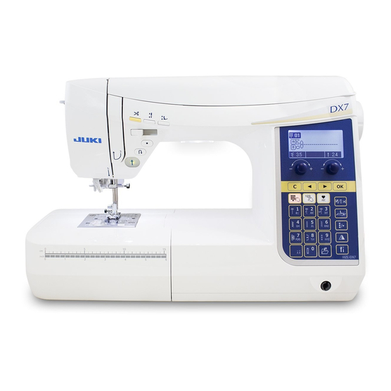
[1] Specifications of HZL-X Series (1) Power switch • 220-240V AC common to 50/60 Hz • 120V AC common to 60 Hz (2) Power consumption • 75 W (3) Dimensions and weight • Dimensions Main unit: 445 (width) × 210 (depth) × 290.5 (height) (mm) Case set: 510 (width) ×... - Page 4 (8) Pattern selection • 10-pattern direct selection: MENU key + Numeric keys • Dot-matrix LCD (9) Number of patterns that can be selected • Max. 70 patterns (10) Number of patterns • HZL-DX7 : 300 • HZL-DX5 : 200 (11) Automatic threading device • The hook section makes a turn by lowering the threading lever, and automatically returns to its original position after completion of threading.
-
Page 5: Search By Trouble (Related To Mechanical Components)
[2] Search by trouble (related to mechanical components) Phenomenon Item to be checked Faulty thread tension 6-8: Position of the hook rotation stopper plate 6-9: Adjusting the bobbin thread tension 6-10-2: Pretension disk opening amount 6-10-3: Tension disk opening amount 6-10-4: Base tension opening amount 6-11: Adjusting the needle thread tension Stitch skipping... -
Page 6: Principal Parts
[3] Principal parts Presser foot auto lift button Thread tension adjustment dial Needle up/down button Spool cap (large) Thread trimming button Spool pin Presser foot pressure adjustment dial Bobbin winding Face cover shaft Threading lever Speed controller LCD Screen Presser foot lifting lever Light under arm Sensor pinhole for buttonholing DX7 Only Thread cutter Operational buttons Lock stitch button Start/stop button Reverse stitch Auxiliary bed... -
Page 7: Disassembling The Machine Covers
[4] Disassembling the machine covers ○ To remove the top cover, bow the hinge section of the right side of the cover. 1) Top cover ○ Remove setscrews 1 and 2 from the face cover. 2) Face cover Then, remove the face cover. ○ Remove setscrews 3 and 4 from the throat plate. 3) Throat plate Then remove the throat plate. - Page 8 ○ Remove setscrew 5 from the thread tension cover. 4) Spool cover Remove the thread tension cover. ○ Remove setscrews 6 to !0 from the spool cover. ○ Pull out the cable of bobbin winder motor from the microcomputer PCB. ○ Remove the spool cover from the main unit of the machine, paying attention to the base tension.
- Page 9 ○ Remove setscrews !3 to !5 from the rubber cushion of the bed cover. Remove 6) Bed cover setscrew !6 from the bed cover. Remove setscrew B !7 from the bed cover. Pull out the bed cover from the metal plate !8 in the direction of the arrow. !7 !8 ○ Remove setscrew !9 from the upper cover of the free arm. 7) Upper cover of the free Remove the upper cover.
- Page 10 ○ Remove setscrews @2 and @3 from the front panel. 9) Front panel ○ Put a thin screwdriver in the notch in the rising section under the arm and pry off the front panel and hook A of the rear panel. ○...
-
Page 11: Pcb Connection Diagram
[5] PCB connection diagram • Microcomputer PCB (Common to HZL-X Series) Connec- Termi- Destination tor No. nal No. LED2 下糸巻き フラッシュ書込み 主軸検知 CN10 SW/slide volume LED G LED R Reverse stitch switch 押え上げ 押え高さ CN10 S/S switch Thread trimming switch... - Page 12 Connector No. Destination Terminal No. CN19 Thread trimming STM 8.5Ω 8.5Ω CN20 Controller socket Controller CN21 Motor filter PCB Main motor (+) (29V) Main motor (-) CN22 Power supply relay lead wire CN23 Straight stitch slide plate Straight stitch slide plate switch sensor PCB CN24 Reserve 1 (Not installed)
- Page 13 • Display PCB HZL-DX7 HZL-DX5 To be connected to CN15 of microcomputer PCB To be connected to CN15 of microcomputer PCB Connector No. Destination Terminal No. Touch switch sheet 2-29 Touch switch signal Microcomputer panel I/F cable (asm.) UART Tx UART Rx Clock signal –...
- Page 14 • Connection block diagram – 12 –...
-
Page 15: Adjustment
[6] Adjustment 6-1 Adjusting the needle bar height ○ Remove the face cover. Adjustment value: ・ Distance from the bottom end of the pin inside needle bar surface to the top surface of the throat plate: 19 mm ・ When the needle is mounted, the needle eye tilts rightward by 2 degrees. Adjustment procedure 1. 1. Select the straight stitch using the pattern selecting button. Choose center needle position. 2. Make a gauge needle by cutting a household needle HA×1 to dimension A. Fit the gauge needle into the needle bar. 3. Prepare an appropriate metal plate of thickness B. (A = 19 mm - B) 4. Bring the needle bar to its lowest dead point. Slightly loosen needle bar connecting stud setscrew 1 as long as the needle does not slip off from the connecting stud. -
Page 16: Adjusting The Needle Entry Point
6-2 Adjusting the needle entry point ○ Remove the face cover. Adjustment procedure 1. Select the straight stitch using the pattern selecting button. Choose center needle position. 2. Assemble a needle #14 into the needle bar, loosen the setscrew in the eccentric collar and adjust the feed bar eccentric collar so that the needle meets the center of the needle slot in the throat plate when it reach- es the top surface of the throat plate by turning the hand wheel. Setscrew Feed bar eccentric collar 6-3 Feed dog height ○ Do not remove the throat plate. Adjustment procedure 1. Set the amount of feed to 0 (zero). 2. Turn the hand wheel to bring the feed dog to its highest dead point. -
Page 17: Timing Belt
6-4 Timing belt ○ Remove the front panel and the microcomputer PCB. Adjustment procedure 1. Loosen the setscrew in the idler mounting base and loosen the timing belt. 2. Turn the hand wheel to bring the needle bar to its lowest dead point. 3. Turn the hook driving shaft to bring the feed dog to its lowest dead point. 4. Carefully keeping the condition described in steps 2 and 3, set the timing belt on the hook driving shaft pulley (by temporarily tightening the setscrew in the idler mounting base) so that the setscrew No. 2 in the pulley is brought to just underside of the pulley. 5. Applying 0.98 ± 0.29 N force to the idler by means of a spring scale, securely tighten the setscrew. Push the middle part of the screw with the spring scale. Setscrew of the idler mounting base The setscrew No. 2 is located just underside of the hook driving shaft pulley. 6-5 Feed timing ○ After checking the feed dog height and the needle bar height, carry out adjustment of the feed timing. -
Page 18: Timing Between The Needle And The Hook
6-6 Timing between the needle and the hook ○ Remove the throat plate, the bed cover and the bottom cover of the free arm. Method for checking 1. Check to be sure that the needle entry point and needle bar height are correct. 2. Select the straight stitch. Select the right needle position by using the zigzag width adjusting dial. (The needle entry point is shifted to the rightmost side.) 3. Now, turn the hand wheel by hand to bring the needle bar to its lowest dead point. 4. Turn the hand wheel further to gradually lift the needle bar until point C where the needle center is aligned with the tip of blade point of the hook is reached. 5. At this time, check to be sure that the distance D from the tip of blade point of the hook to the upper end of the needle eye is 3.1 to 3.3 mm. If this distance is not correctly provided, carry out the following adjust- ment. Adjustment procedure 1. Loosen the setscrew in the hook driving gear which is not visible from underside of the sewing machine when the needle center aligns with the tip of blade point of the hook. 2. Select the straight stitch and the right needle position. Move the hook driving gear in the rotational direc- tion to adjust distance D of 3.1 to 3.3 mm is provided between the tip of blade point of the hook and the upper end of the needle eye when the needle bar is lifted by 1.6 mm from the lowest dead point by turning the hand wheel by hand. -
Page 19: Clearance Between The Needle And The Blade Point Of Hook
6-7 Clearance between the needle and the blade point of hook ○ Remove the face cover and the throat plate. Adjustment procedure 1. Loosen screw . Adjust the clearance between the needle and the blade point of the hook to 0.02 to 0.07 mm by turning adjusting shaft 0.02 to 0.07 mm Adjusting the balance of the clearances at the right and left needle entry points 1. Select the zigzag pattern and set the zigzag width to 7 mm. Adjust the balance of the clearances provided between the needle and the blade point of the hook at the right and left needle entry points. Left needle position Right needle position Left needle position Right needle position If the clearance is larger at the right needle If the clearance is larger at the left needle... -
Page 20: Position Of The Hook Rotation Stopper Plate
6-8 Position of the hook rotation stopper plate ○ Remove the throat plate. Adjustment procedure 1. When the bobbin case holder is placed inside the rotating hook, loosen the setscrew and determine the longitudinal position of the rotation stopper plate so that the projection of the bobbin case holder and the leaf spring of the rotation stopper plate are located as illustrated in the enlarged partial view. To adjust the lateral position of the rotation stopper plate, press the plate in the right direction by the amount of play and secure with the setscrew. * The hook race surface and the bobbin case holder may be stained with dirt, oil or grease. Wipe them off with an alcohol-soaked cloth where necessary. If those parts are left stained, chattering or thread slip-off noise of the bobbin case holder can occur. Adjust so that the projection and Setscrew leaf spring are aligned with this line. Enlarged partial view 6-9 Adjusting the bobbin thread tension ○... -
Page 21: Adjusting The Disk Opening Amount
6-10 Adjusting the disk opening amount 6-10-1 Adjusting the thread tension release adjusting plate ○ Remove the face cover, the thread tension cover and the spool cover. Adjustment procedure 1. Raise the presser foot lifting lever. 2. Loosen the adjusting screw and adjust the thread tension release adjusting plate so that the top end of claw of the opening arm aligns with the marker dot on the thread releasing arm. Thread tension release adjusting plate Thread releasing arm Opening arm... -
Page 22: Tension Disk Opening Amount
6-10-3 Tension disk opening amount ○ Remove the face cover, the thread tension cover and the spool cover. Adjustment procedure 1. Maximize the tension with the thread tension ad- justment dial. Raise the presser foot lifting lever. 2. Adjust the clearance between tension disks (A) and (B) to 1 mm by turning the thread tension float adjusting screw. Disk B Disk A 1 mm 6-10-4 Base tension opening amount ○... -
Page 23: Adjusting The Needle Thread Tension
6-11 Adjusting the needle thread tension ○ Remove the thread tension cover. Adjustment procedure 1. Raise the presser foot lifting lever. 2. Turn the thread tension adjustment dial to bring its "AUTO" section to the top. 3. Prepare SHAPPE Span thread #60 and a tension gauge. Thread the base tension and the tension disk. 4. Lower the presser foot lifting lever. Turn the adjusting nut to adjust the tension so that the tension gauge gives a reading of 0.49 to 0.59 N. Adjusting nut – 21 –... -
Page 24: Vertical Position Of The Needle Threading Hook
6-12 Vertical position of the needle threading hook ○ Remove the face cover. Adjustment procedure 1. Assemble a household HA×1 needle #11 into the needle bar. 2. Turn the hand wheel to bring the needle bar near its highest dead point and stop the hand wheel when the needle bar reaches the location where the setscrew in the needle bar guide is visible. 3. Lower the threading lever to its lowest dead point. Check whether a clearance of 0 to 0.1 mm is provided between the top end of the needle threading hook and the upper end of the needle eye. (If the clearance is not 0 to 0.1 mm, the needle may not be threaded depending on the size of the needle used.) 4. Fit a hexagonal wrench on the needle bar guide setscrew to loosen it slightly. -
Page 25: Adjusting The Auxiliary Hook Height
6-13 Adjusting the auxiliary hook height ○ Remove the face cover. Adjustment procedure 1. Loosen the locknut. Adjust the adjusting nut so that the distance shown in the enlarged partial view is ob- tained. 2. Tighten the locknut to fix the adjusting nut. Adjusting nut Locknut Enlarged partial view (Caution) If the thread does not enter the guide slit of the needle threading hook when threading the nee- dle, check the distance and adjust it correctly. -
Page 26: Adjusting The Opening Amount Of Auxiliary Hook
6-14 Adjusting the opening amount of auxiliary hook Adjustment procedure 1. Adjust the adjusting screw to the distance shown in the enlarged partial view. Adjusting screw 6 ± 0.2 mm Enlarged partial view Auxiliary hook (Caution) If the auxiliary hook still keeps the thread after completion of needle threading, or if the auxil- iary hook releases the thread before the needle threading hook catches the thread, adjust the adjusting screw. -
Page 27: Motor Belt
6-16 Motor belt ○ Remove the front panel. Adjustment procedure 1. Set the motor timing belt to the motor pulley and the motor shaft pulley. 2. Adjust the motor bracket so that the belt deflection amount becomes 6 ± 1 mm when pressing the center of the belt with a force of 0.98 N. After completion of adjustment, tighten the setscrew in the motor bracket. Motor pulley 6 ± 1 mm Motor bracket 0.98 N Setscrew of the motor bracket Motor shaft pulley Setscrew of the motor bracket – 25 –... -
Page 28: Automatic Thread Trimming
6-17 Automatic thread trimming 6-17-1 Lateral position of the thread trimming mechanism base Adjustment procedure 1. Turn the power switch OFF. Then, turn the power switch ON with the reverse stitch button and the thread trimming button held pressed simultaneously. 2. The Service mode screen is displayed. Select "12". 3. Press the automatic back-tack thread trimming button to activate the thread trimming mechanism. 4. In the aforementioned state, loosen two adjusting screws and move the thread trimming mechanism base laterally with pressed in P direction until the rear end of the catching unit is aligned with the marker line. Then, tighten the adjusting screws. Adjusting screw Thread trimming mechanism base... -
Page 29: Phase Of The Catching Unit Driving Cam
6-17-2 Phase of the catching unit driving cam ○ Carry out the adjustment with the power OFF. Adjustment procedure 1. Loosen setscrews 1 and 2 . 2. Turn the cam driving shaft in the direction of the arrow as shown in Fig. A, and the catching unit driving cam will rotate in the direction as shown in Fig. B. Turn the cam until it comes in contact with the pin. 3. -
Page 30: Replacing The Thread Trimming Blade
6-17-3 Replacing the thread trimming blade 1. Remove the throat plate. 2. Remove the setscrew of the thread trimming knife cover. Remove the thread trimming knife cover, the thread trimmer grasping unit and the thread trimming knife. 3. Reversing the disassembly procedure, assemble the parts. (Refer to the Caution below.) Setscrew of the thread trimming blade cover Thread trimming blade cover Thread trimmer grasping unit... -
Page 31: Longitudinal Feed
6-18 Longitudinal feed Preparation for adjustment Turn OFF the power switch. Keep pressing both the reverse stitch button and thread trimming button simul- taneously and turn ON the power switch. The service mode screen appears on the display. Select "No. 3" to change over the screen to the sewing pattern for adjusting darning. Adjustment procedure Sew a darning sewing pattern three times under the aforementioned sewing conditions. Turn the stitch length adjusting dial in the case of the DX7 model, or press the stitch length adjusting button in the case of the DX5 model to adjust so that the bottom end of the left row seam and that of the right row seam of the third pattern lie on a straight line as illustrated in the sketch (tolerance 0 ± 1 mm). 〜 Direction of adjustment of lengthwise feed • In the case the lower end of the right line is ⇨ Adjust in "+" direction higher than the lower end the inner left line... -
Page 32: Knee Lifting Wire
6-19 Knee lifting wire ○ Remove the face cover, the thread tension cover and the spool cover. Adjustment procedure 1. Assemble the knee lifting lever 1 . 2. Loosen the locknut 3 . Adjust the wire 4 so that the height of presser foot 2 becomes 12 mm when -0.5 you fully turn the knee lifter lever 1 in the direction of the arrow until it will go no further. -
Page 33: Automatic Presser Foot Lifting
6-20 Automatic presser foot lifting 6-20-1 Auto-lifter cam lever ○ Remove the front panel and the microcomputer PCB. Adjustment procedure 1. Check to be sure that auto-lifter cam 1 is at its origin position (see the figure below). (Turn the power ON before starting the adjustment to bring auto-lifter cam 1 to its origin position.) 2. Assemble the throat plate. Assemble the standard presser foot (presser foot A) in the presser foot holder. Lower the presser foot. At this time, check to be sure that the feed dog does not appear above the top surface of throat plate. 3. Loosen the setscrew 2 of the cam lever. 4. -
Page 34: Presser-Lifter Position Sensor
6-20-2 Presser-lifter position sensor ○ Remove the rear panel. Remove the entire unit of needle throwing STM base. * Adjust the position of mesh of sensor gear 2 and the gear of sensor rack 5 with each other when installing press- er-lifter position sensor mounting plate 1 . (See Fig. C.) Adjustment procedure 1. Temporarily tighten setscrew 6 of the presser-lifter position sensor mounting plate. 2. -
Page 35: Adjusting The Height Of The Presser Foot When It Is Lifted
6-20-3 Adjusting the height of the presser foot when it is lifted * Be sure to carry out the following adjustment every time you have adjusted the knee-lifter wire, auto-lifter cam lever or presser-lifter position sensor. 6-20-3-1 Adjusting the presser foot height to 0 (zero) mm Adjustment procedure 1. Select "No. 21 : 0MM SETTING" of the service mode. - Page 36 6-20-3-2 Adjusting the presser foot height to 6 mm Adjustment procedure 1. Select "No. 22 : 6MM SETTING" of the service mode. At this time, check to be sure that the feed dog does not appear above the top surface of throat plate. 2. When "No. 22 : 6MM SETTING" is selected, the presser foot goes up by approximately 6.5 mm. If not, turn the stitch length adjusting dial in the "+" direction in the case of the DX7 model, or press the stitch length adjusting button in the case of the DX5 model to lift the presser foot by approximately 6.5 mm. 3. Place a block or the like thickness of which is 6 mm under the presser foot. Operate the sewing machine in increments of 1 pulse in the "-" direction to lower the presser foot until its vertical play is eliminated. * Be sure to adjust the presser foot height by lowering it from its upper position. If you excessively lower the presser foot, lift the presser foot again by approximately 6.5 mm. 4. Press the "OK" button.
-
Page 37: Straight Stitch Slide Plate
6-21 Straight stitch slide plate 6-21-1 Adjusting the position of the straight stitch slide plate ○ Remove the throat plate. Adjustment procedure 1. Temporarily tighten the setscrew 1 of the lever holder. 2. Move operating lever 3 to the left to set straight stitch slide plate 2 in the "straight stitch selection". 3. Adjust the vertical position of lever holder 4 so that the edge of needle hole in straight stitch slide plate 2 protrudes from the edge of needle slot in the throat plate by 0 to 0.2 mm. Then, tighten the setscrew 1 of the lever holder. -
Page 38: Straight Stitch Slide Plate Sensor Pcb
6-21-2 Straight stitch slide plate sensor PCB ○ Remove the throat plate. Adjustment procedure 1. Temporarily tighten the setscrew 1 of the straight stitch slide plate sensor PCB. 2. Attach the throat plate. Slowly move operating lever 3 of straight stitch slide plate 2 to find the position at which straight stitch slide plate changes over its mode to the "straight stitch selection". (Buzzer sounds at the moment of changeover.) 3. -
Page 39: Service Mode
6-22 Service mode 6-22-1 Service mode screen Check with item numbers and items. [How to select the service mode] 1. When the power switch stays off, keep pressing both the reverse feed button and the thread trimming button simultaneously to turn ON the power switch. 2. The service mode screen appears on the display. Select the number corresponding to the service item to operate. * To select the number corresponding to a target service item, shift the item shown on the screen forward or backward one after another by pressing the selection button until the number correspond- ing to the target item is selected. 6-22-2 Service-mode items and descriptions Item name Description Select the straight stitch pattern and set the amount of feed at 0 (zero). - Page 40 Item name Description Thread trimming condition can be checked. Perform thread trimming halfway by using the "OK" button. THREAD TRIM CHECK From this condition, manually turn the main shaft to carry out the thread trim- ming sequence in order. SARA UKASHI Bring the disks to the floating condition. (Tension release) Operate the "OK" button, and the disks will float. The maximum sewing speed is 500 sti/min (SPM) when the straight stitch STRAIGHT 500STI/MIN pattern is selected.
- Page 41 Item name Description The bobbin winder is provided with the function that winds thread with in- creased power. This function is used when winding thick thread or an increase in torque is required. The threshold value for the increase in power is set using WIND PWR UP LIMIT this item of the service mode. The adjustable range of the threshold value is [20 to 60].
- Page 44 HOUSEHOLD SEWING MACHINERY BUSINESS UNIT 2-11-1, TSURUMAKI, TAMA-SHI, TOKYO, 206-8551, JAPAN PHONE : (81)42-357-2341 FAX : (81)42-357-2380 http://www.juki.com Copyright C 2015 JUKI CORPORATION All rights reserved throughout the world. 40166659 2015/08...
Need help?
Do you have a question about the HZL-X Series and is the answer not in the manual?
Questions and answers