
Related Manuals for Sea-Bird Scientific SBE 39plus


Summary of Contents for Sea-Bird Scientific SBE 39plus
- Page 1 User manual SBE 39plus-IM temperature recorder Document No. SBE39IM Release Date: 2023-03-21 Version: 425-643-9866 seabird.com...
-
Page 3: Table Of Contents
Table of Contents Section 1 Safety information ......................3 1.1 Hazard information........................3 1.2 Equipment labels.......................... 4 Section 2 SBE 39plus IM quick start guide ................... 5 Section 3 Specifications ........................7 3.1 Mechanical........................... 7 3.1.1 Dimensions..........................7 3.2 Electrical ............................. 8 3.3 Communication........................... - Page 4 Table of Contents Section 9 Reference: command descriptions ................39 9.1 Integrated IMM........................... 39 9.2 SIM commands.......................... 40 9.3 Acquisition micro-controller ....................... 40 9.3.1 Status..........................41 9.3.2 General setup........................43 9.3.3 Memory setup........................43 9.3.4 Output format setup......................43 9.3.4.1 Diagnostic data format .................... 44 9.3.4.2 XML data format.......................
-
Page 5: Section 1 Safety Information
Section 1 Safety information Please read this entire manual before this equipment is unpacked, set up, or operated. Pay attention to all danger, warning, and caution statements. Failure to do so could result in serious injury to the operator or damage to the equipment. D A N G E R Indicates a potentially or imminently hazardous situation which, if not avoided, will result in death or serious injury. -
Page 6: Equipment Labels
Safety information 1.2 Equipment labels Read all labels and tags attached to the equipment. Personal injury or damage to the equipment could occur if not observed. A symbol on the equipment is referenced in the manual with a precautionary statement. Electrical equipment marked with this symbol may not be disposed of in European domestic or public disposal systems. -
Page 7: Section 2 Sbe 39Plus Im Quick Start Guide
Section 2 SBE 39plus IM quick start guide This quick start guide gives the steps necessary to make sure that the SBE 39plus IM sensor operates correctly and collects data before it is deployed. This quick start guide and user manual applies to those SBE 39 models that are equipped with an Inductive Modem Module (IMM) or Surface Inductive Modem (SIM). - Page 8 SBE 39plus IM quick start guide...
-
Page 9: Section 3 Specifications
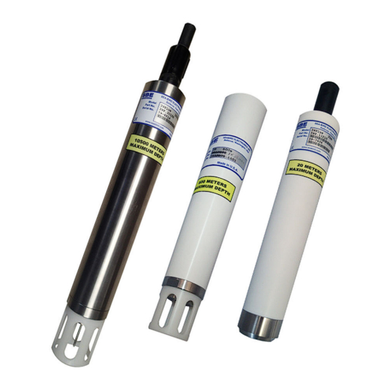
Optional strain-gauge pressure sensor 20, 100, 350, 600, 1000, 2000, 3500, 7000 m Weight in air, water, with embedded thermistor 0.6 kg, 0.25 kg 1.2 kg, 0.7 kg 3.1.1 Dimensions Figure 1 SBE 39plus-IM lengths Figure 2 SBE 39plus fairing... -
Page 10: Electrical
Specifications 3.2 Electrical Temperature Temperature and pressure Internal batteries 4 Saft LS 14500 AA lithium cells, 7.2 V, 5.2 Ah Input 9-30 VDC Current draw (2.5 mA, 280 mseconds): 0.00070 A-sec (3 mA, 280 mseconds): 0.00084 A-sec Current draw, low power 25 µA 3.3 Communication Temperature... -
Page 11: Section 4 Overview
• Fairing ("net fender") to protect from fishing lines and nets. The SBE 39plus-IM is equipped with an internal battery pack and uses an Inductive Modem (IM) to transmit data and get commands over a plastic-covered steel mooring cable. The cable uses Differential-Phase-Shift-Keyed (DPSK) telemetry. No electrical cables or connectors are required. - Page 12 39plus is deployed with the thermistor pointed up, the battery life may be reduced by up to 40%. This will not affect most deployments because even with a 40% reduction, the SBE 39plus could still collect approximately 7.4 million samples, more than the memory can store.
-
Page 13: Section 5 Set Up Sensor And Verify Operation
Section 5 Set up sensor and verify operation Set up the hardware and install the software for the sensor to make sure that it functions correctly before deployment. • Install the manufacturer-supplied software. • Verify operation. IMPORTANT:all commands are pre-pended with #ii. Do not use #ii for RS232 and SDI-12 protocols. -
Page 14: Set Up Sim
Set up sensor and verify operation SetConfigType=2 SetEnableAutoIMFlag=0 SetEnableBackSpace=1 SetEnableBinaryData=0 SetEnableEcho=1 SetEnableHostFlagConfirm=0 SetEnableHostFlagTerm=0 SetEnableHostFlagWakeup=0 SetEnableHostPromptConfirm=0 SetEnableHostServeOnPwrUp=1 SetEnablePrompt=1 SetEnableHostWakeupCR=0 SetEnableSignalDetector=0 SetTermFromHost=36 SetTermToHost=13 b. Option: IMM emulates the SIM *Init *Init (send twice to set IMM to default state) SetConfigType=1 SetEnableBinaryData=0 5. Send the GetCD command to verify that the IMM is set up correctly 5.1.2 Set up SIM Verify that the sensor and modem operate correctly before deployment. - Page 15 Set up sensor and verify operation 2. Remove the J5 jumper from the SIM. This puts a 1K resistor in series with the inductive loop and reduces signal amplitude, so that any other MicroCATS that are close to the connected sensor do not respond to commands.
-
Page 16: Install Software And Test Sensor
The software automatically looks for the serial port number of the connected sensor. 3. At the Instruments menu item, select SBE 39plus-IM. 4. Push OK to close this window. The main window opens. The area on the left shows available commands. The large area on the right shows commands and the responses from the sensor to those commands. -
Page 17: Set Up Sensor Id And Test Imm
Select (default) or deselect the option to Prompt to launch data conversion after data upload. 5.3 Set up sensor ID and test IMM 1. From the Instrument menu, select SBE 39plus IM. SeatermIM starts. 2. For IMM: after the first use, the software will send DS to automatically try to connect. -
Page 18: Set Up Sensor Id And Test Sim
The sensor is ready for application-specific setup and deployment. 5.4 Set up sensor ID and test SIM 1. From the Instrument menu, select SBE 39plus IM. SeatermIM starts. 2. For SIM: after the first use, the software will send DS to automatically try to connect... - Page 19 Set up sensor and verify operation • If the software is set to "Automatically get instrument ID" it sends id? and waits for the sensor to communicate. The software then sends !iiGetHD and #iiGetHD to the ID sent by the sensor. •...
-
Page 20: Set Up And Test Usb Communication
Connect the USB cable to the USB port on the PC. 2. Start Seaterm V2. 3. From the Instruments menu, select SBE 39plus IM USB. SeatermUSB-SBE39plus-IM opens. If there is only one USB device connected the software should automatically connect to it (it may be necessary to select Refresh). If there is more than one device connected, select the one you want, then Refresh. -
Page 21: Set Up And Test Rs232 Communication
Remove the desiccant bag and connect the RS232 connector to the sensor. Connect the RS232 cable to the PC. 2. Start Seaterm V2. 3. From the Instruments menu, select SBE 39plus RS232. Seaterm232 opens. Table 3 Toolbar menu buttons Refresh the connection to the sensor Capture sensor setup to a .cap file... -
Page 22: Mooring Cable And Wiring
5. Make sure all of the data from the sensor is uploaded to the PC. 6. Change any settings in the SBE 39plus Configurations area. 7. Disconnect the RS232 cable from the 39plus. 8. Install new desiccant. - Page 23 Set up sensor and verify operation For a typical cable-to-shore application with a direct connection, the bottom end of the wire is grounded to seawater and the top end is insulated to the connection to the IMM or SIM. A second wire from the IMM or SIM connects to the seawater ground to complete the circuit (16plus-IM shown).
- Page 24 Set up sensor and verify operation...
-
Page 25: Section 6 Deployment And Recovery
Section 6 Deployment and recovery 6.1 Set up sensor Set up the sensor hardware for deployment. The manufacturer recommends that the sensor is deployed with the thermistor end down, or horizontal. This gives maximum battery pack endurance, and keeps sediment out of the thermistor. Hardware setup includes: •... - Page 26 Deployment and recovery b. Put the insulated mooring cable in the grooves of the brackets. Make sure that the cable can pass through freely. If it is too large for the clamps, it may cause damage to the cable and prevent IM communication. c.
-
Page 27: Set Up Software
Deployment and recovery 6.2 Set up software Use the Seaterm V2 software to send commands to either the IMM or SIM or the acquisition microcontroller. • The IMM or SIM (typically at the surface) controls communication between the 39plus and the remote IMM or SIM. Commands have a ! prefix. •... -
Page 28: Timeout Description
Deployment and recovery • !iiSetGDataStr= to define the commands sent to the acquisition microcontroller when GData is sent, and then GData to start data collection for all IM sensors online, to collect a sample every #iiSampleInterval seconds. 7. To use the software to see data while the sensor collects data, select Capture to save that data to a file. -
Page 29: Controlled (Polled) Mode
Deployment and recovery Note that the sensor has a lockout feature to prevent interference with data collection. if the sensor is in operation or ready to start, only these commands can be sent: • All remote SIM or IMM • Integrated IMM—Get, GData, ID?. -
Page 30: Recover Sensor From Deployment
Deployment and recovery Response to !iiData with #iiOutputFormat=1, #iiFormat=0, ID=3, pressure sensor installed, #iiTxSampleNum=y ID, serial number, temperature, date, time, sample number, number of samples in average Example output: 03, 09999, 8.5796, 531.316, 14 Jul 2016, 09:01:34, 1126, 250 6.6 Recover sensor from deployment D A N G E R If the system stops while under water or shows other signs of damage, it may be flooded. -
Page 31: Section 7 Transmit And Convert Data
Connect the USB connector to the sensor and a PC. 2. Start the Seaterm V2 software. 3. At the Instruments menu, select SBE 39plus IM USB. The software should automatically connect to the device. If there is more than one sensor, select the correct device, then select Refresh. -
Page 32: Use The Im Telemetry To Transmit Data
7.1.1 Use the IM telemetry to transmit data To upload small amounts of data from the sensor to a PC, use the IM telemetry. 1. From the Instrument menu, select SBE 39plus IM. SeatermIM starts. 2. The software detects whether it is connected to an IMM or a SIM. The next step depends on the ID configuration in the software from the last time it was used. -
Page 33: Convert Data
Transmit and convert data d. If there is still no communication, check the cable and connections with the SIM or IMM, the sensor, and the PC. e. If there is still no communication, do step 1 with a different COM port or different fixed ID and try to connect again. - Page 34 Transmit and convert data 1. To convert the .xml data: • In SeatermUSB, push Convert XML Data. • In SeatermIM, select Convert XML Data in the Tools menu. The Convert Data window opens. 2. In the "Input file" area, push Browse to find the .xml file to convert. 3.
-
Page 35: Section 8 Maintenance
Section 8 Maintenance W A R N I N G If the user thinks that a sensor has water in the pressure housing: Disconnect the sensor from any power supply. Put on safety glasses and make sure that the sensor is pointed away from the body and other people. -
Page 36: Clean Pressure Sensor
Do not put a brush or any object in the pressure port. It may damage or break the pressure sensor. If the SBE 39plus is equipped with the optional pressure sensor, make sure to examine and clean it at regular intervals (approximately annually). -
Page 37: Calculate Pressure Correction
Maintenance 1. Unscrew the pressure port plug from the pressure port (shown below with an external thermistor). 2. Flush the pressure port with warm de-ionized water to remove any debris. 3. Replace the pressure port plug. 4. Let the 39plus equilibrate at a stable temperature for at least 5 hours before operation. -
Page 38: Clean Bulkhead Connectors
Maintenance 3. Replace an O-ring if necessary. ® ® 4. Apply a small quantity of silicone-based Parker Super O Lube or Dow Corning high vacuum grease to each O-ring. • The lubricant helps the O-ring move into its groove with no twist, which can compromise the seal. -
Page 39: Calibration
Maintenance ® • Dow Corning 4 Electrical Insulating Compound (DC 4) ® • Dow Corning Molykote 44 High Temperature Grease (DC 44) Use a finger to put a small quantity (approximately 1 cm in diameter) of silicone grease on the socket end of the connector and push as much of the lubricant as possible into each socket. -
Page 40: Spare Parts And Accessories
Maintenance 8.6 Spare parts and accessories Part number Description Quantity 50504 Saft 3.6 V size AA Lithium batteries 172557 USB type A to Mini-B cable, 1.8 m 801836 39plus internal data I/O cable, 0.3 m 801263 Data/power interface cable, MCIL4FS to DB9S and battery snap , 2.4 m 801206 Data/power interface cable, MCIL4FS to DB9S with red-black twisted wire leads 20200.0... -
Page 41: Section 9 Reference: Command Descriptions
Section 9 Reference: command descriptions This is a reference for advanced users. The values of these commands are stored in the sensor until the user changes them. Notes about terminal commands are listed below. • Commands are not case-sensitive. Use "Enter" to store a command. •... -
Page 42: Sim Commands
Reference: command descriptions !iiGetHD Show the hardware information of the integrated IMM. !iiGetSD Show the status information of the integrated IMM. Test command Test the integrated IMM. The line must be captured before command is sent. iiTestCableCoupler Get Data commands !iiGDataStr=x x = characters to sent to 39plus acquisition microcontroller from the integrated IMM when GData is sent from the remote IMM or SIM. -
Page 43: Status
Reference: command descriptions • #ii = 39plus ID 0–99. To transmit to the 39plus-IM specified. Example: #02datetime=04082016073500 sends a command to the sensor with ID=02 to set the date and time to April 8, 2016 07:35:00. • #Sx = IMM serial number, date and time. Use instead of #ii to transmit to the specified serial number of the IM. - Page 44 Reference: command descriptions #iiGetCC Show calibration coefficients. Should agree with the Calibration Certificate that shipped with the sensor. #iiGetEC Show event counter. Reset with #iiResetEC. Some events include: PowerOnReset: occurs each time the lithium cells are removed and replaced OutOfMemory: memory is full. User needs to upload data from sensor LowBatteryVoltage: low battery voltage sensed during data collection WatchdogReset: sensor resets if microcontroller is not sensed, and operation continues LoggingRestartPON: power turned off then on during data collection.
-
Page 45: General Setup
Reference: command descriptions • Lines that give information about parameters such as temperature, pressure, and sample number will only show if they are enabled and #iiOutputFormat=1 or 2. #iiOutputFormat=0 is not affected. • The #iiDS response is also affected by the #iiLegacy= command (refer to the Output Format Setup Commands section for details.) •... -
Page 46: Diagnostic Data Format
Reference: command descriptions #iiSetCoastal x=0: set units to °C and dbar, enable temperature and pressure output, disable sample number output. x=1: set units to °C and psi, enable temperature and pressure output, disable sample number output. #iiLegacy=x x=0: allow all commands (default) x=1: reset units to °C and dbar, enable temperature, pressure. -
Page 47: Autonomous Operation With Data Storage
Reference: command descriptions Output format, sensors equipped with inductive modem 039xxxxx, tttt.tttt, ppppp.ppp, smpl, navg, yyyy-mm-ddThh:mm:ss S/N, temperature, pressure, sample number, number of samples in average, salinity, sound velocity, specific conductivity (S/m), sample number, date, time Example output: <?xml version="1.0"?>,datapacket><hdr><mfg>Sea-Bird</mfg><model>39plus- Im</model><sn>03720132</sn></hdr><data><t1>24.6671</t1><p1>0.016</p1><smpl>92</smpl ><navg>35</navg<dt>2018-06-13T15:00:36</dt></data></datapacket>... -
Page 48: Controlled ("Polled") Data Collection
Reference: command descriptions 9.3.6 Controlled ("polled") data collection #iiTS Collect a sample and transmit data. #iiTSR Collect a sample and transmit raw data. #iiTSS Collect a sample, store data in flash memory, transmit data and turn power off. If the USB is connected, the power will not turn off. - Page 49 Reference: command descriptions #iiGetSamples:b,e Upload sample b to sample e, in format specified by #iiOutputFormat= . First sample number is 1. Maximum is 250. For example: #01getsamples:1,200 will upload samples 1–200 from sensor with ID=01. #01getsamples:1 will upload the first sample #01getsamples will upload all samples in memory...
- Page 50 Reference: command descriptions...
-
Page 51: Section 10 General Information
Section 10 General information W A R N I N G This product can expose the user to chemicals with silica, crystalline (airborne particles of respirable size), which is known to the State of California to cause cancer and birth defects or other reproductive harm. - Page 52 General information...
- Page 54 Sea-Bird Electronics 13431 NE 20th Street Bellevue WA 98005 U.S.A. (425) 643-9866 © Sea-Bird Electronics, Inc., 2023. All rights reserved. Printed in USA. *SBE39IM*...
Need help?
Do you have a question about the SBE 39plus and is the answer not in the manual?
Questions and answers