
Related Manuals for Sea-Bird Scientific SBE 11plus V2


Summary of Contents for Sea-Bird Scientific SBE 11plus V2
- Page 1 User manual SBE 11plus V2 Deck Unit for use with SBE 9plus Document No. SBE11plusV2 Release Date: 2023-04-13 Version: Software: Seasoft V2 425-643-9866 seabird.com...
-
Page 3: Table Of Contents
Table of Contents Section 1 Safety information ......................3 1.1 Hazard information........................3 1.2 Equipment labels.......................... 3 Section 2 Specifications ........................5 2.1 Deck Unit specifications......................5 2.2 Cable descriptions........................5 Section 3 Description of SBE 911plus ................... 7 3.1 Deck Unit front panel........................8 3.2 Deck Unit back panel......................... - Page 4 Table of Contents 7.1 Deck Unit LED display format....................37 7.2 Raw data format......................... 38 7.2.1 IEEE488 data format......................38 7.2.2 RS232 data format......................40 7.2.3 NMEA data format......................40 7.2.4 Pressure frequency and pressure temperature data format..........41 7.2.5 Converted data output data format..................41 7.3 Calculate engineering units in Seasave..................
-
Page 5: Section 1 Safety Information
Section 1 Safety information Please read this entire manual before this equipment is unpacked, set up, or operated. Pay attention to all danger, warning, and caution statements. Failure to do so could result in serious injury to the operator or damage to the equipment. D A N G E R Indicates a potentially or imminently hazardous situation which, if not avoided, will result in death or serious injury. - Page 6 Safety information EFUP: Hazardous material exists over the threshold of GB/T 26572.2011. The number in the center of the symbol is the Environmentally Friendly Use Period as specified by SJ/T 11364-2014, China's marking for the Restriction of the Use of Hazardous Substances in Electrical and Electronic Products. This product should be recycled after its environmentally friendly use period.
-
Page 7: Section 2 Specifications
Section 2 Specifications 2.1 Deck Unit specifications Power requirements 120 VAC at 60 Hz, 1.75 A or 240 VAC at 50 Hz 1 A switchable Sea cable compatibility Single- or multi-core armored cable to 10000 m long with inner core resistance of up to 350 ohms Dimensions 14.3 cm tall, 37.5 cm deep, 44.4 cm wide cabinet. - Page 8 Specifications Deck Unit Function Pin A Ground Pin B CDO RS232 RX Pin C CDO RS232 TX Pin D Raw pressure RS232 TX Pin E Power, +12 VDC 5-contact to 4-contact: SBE 11 to surface PAR sensor Deck Unit Function Surface PAR Pin A Signal ground...
-
Page 9: Section 3 Description Of Sbe 911Plus
Section 3 Description of SBE 911plus The SBE 11plus V2 is the Deck Unit used with the SBE 9plus CTD for real-time data collection. The 11plus and 9plus can also be used with the 17plus V2 Searam for in-situ data collection. -
Page 10: Deck Unit Front Panel
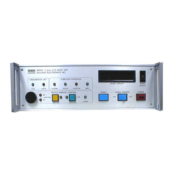
Description of SBE 911plus Figure 1 Schematic of 911plus system with water sampler 3.1 Deck Unit front panel 1. Power—turns power to the Deck Unit on or off. 2. Word Select—thumbwheel switch to select any sensor channel data buffer status, or other diagnostics in the Word Display. - Page 11 Description of SBE 911plus 11. SBE or G.O.—LED stays on to show which water sampler is controlled by SW1 on the Deck Unit or Modem. 12. Home/Arm—Push-button LED. Operation varies for type of water sampler. 13. Fire—Push-button LED. Operation varies with the type of water sampler. SBE 32 Carousel •...
-
Page 12: Deck Unit Back Panel
Description of SBE 911plus 3.2 Deck Unit back panel 1. AC Voltage—Selector switch for 120 VAC at 50 Hz or 240 VAC at 60 Hz. 2. AC Input—Plug for power to Deck Unit. 3. Fuse—5 x 20 mm, 250 VAC Slow-blow; 2 amp for 120 V, 1 amp for 240 V. 4. - Page 13 Description of SBE 911plus...
- Page 14 Description of SBE 911plus...
-
Page 15: Section 4 Connect Cables On Sbe 11Plus System
Section 4 Connect cables on SBE 11plus system D A N G E R Life-threatening voltages of over 250 VDC are on the sea cable and the Deck Unit when it is on, and will persist for up to 1 minute after it is turned off. D A N G E R Make a separate ground connection between the Deck Unit and an isolated power ground. - Page 16 Connect cables on SBE 11plus system Connect the Surface PAR sensor to the Surface PAR Input connector on the back panel of the Deck Unit. The manufacturer supplies an MS3106A14S-2P connector if there is no cable. Remote Unit to Deck Unit Connect to the Remote Out connector on the back panel of the Deck Unit.
-
Page 17: Section 5 Set Up And Configure System
Section 5 Set up and configure system Seasoft V2 software has several components: Seaterm, a terminal launcher; Seasave V7, for real-time data collection; and SBE Data Processing, to process the collected data. 1. Double-click on SeasoftV2.exe to install the manufacturer-supplied software on the 2. - Page 18 Set up and configure system Show model and firmware version SBE 11plus V 5.2 number of scans to average = 8 (set to 1 for full data rate of 24 Hz) PBaud= pressure baud rate = 9600 NMEABaud= NMEA baud rate = 4800 AddSPAR= surface PAR voltage added to scan Offset=...
-
Page 19: Set Up And Configure Ctd
Set up and configure system NMEA baud rate NMEABaud=x x= baud rate for communication between the Deck Unit and the NMEA navigation device, 4800 or 9600. Surface PAR AddSPAR=x x=Y: Add Surface PAR voltage to CTD data. x=N: do not Offset=x x=offset voltage, 0–99, used to adjust Surface PAR data for drift in Deck Unit electronics Pressure baud rate... -
Page 20: Test Nmea In Seasave
Set up and configure system The decoded latitude and longitude data is appended to the CTD data in the Deck Unit and transmitted to the PC to be stored and/or shown with CTD data. The NMEA LED light on the Deck Unit flashes each time data is successfully decoded. This is typically the same rate that the NMEA data is transmitted. -
Page 21: Nmea Interface Commands
Set up and configure system • Connect the SBE 11 Interface RS232 connector on the Deck Unit to the PC. If this connection is not made, noise on the open Sea Cable connector will cause interference with the Deck Unit communication. •... -
Page 22: Nmea Message Format
Set up and configure system x=y: Add latitude and longitude data to CTD data. x=n: Do not add latitude and longitude data to CTD data. 5.3.3 NMEA message format • -- is two device-specific characters. • <CR> is carriage return. •... -
Page 23: Set Up And Configure Surface Par In Seaterm
This data is appended to the CTD data in the Deck Unit and is transmitted to the PC. The Seasave and Data Processing software support several PAR sensors: • Linear or logarithmic Sea-Bird Scientific PAR • Biospherical QSR-240, QCR-240, QSR-2200, QCR-2200. -
Page 24: Set Up And Configure Par In Seasave
Set up and configure system 5.4.2 Set up and configure PAR in Seasave The Deck Unit adds the data from the Surface PAR into the CTD data. The Seasave software stores and can show the PAR data with the CTD data. The software requires a .xmlcon or .con configuration file to add the PAR data to the CTD data. - Page 25 Set up and configure system CDO data automatically shows when the Deck Unit is turned on or reset. The data stops when a line with a <CR><LF> is received by the microcontroller (in Seaterm, push Enter.) 1. Connect the SBE 11 Remote Out connector to the PC. 2.
-
Page 26: Cdo Status Commands
Set up and configure system 5.5.2.1 CDO status commands Show setup parameters Firmware version for Remote Output NAvg=number of scans to average. Deck Unit calculates averages and sends this data to the remote output port at this rate. This is not the same as the number of scans to average that shows in the status command response for the SBE 11 interface. - Page 27 Set up and configure system PT1=F F=pressure T1 PT2=F F=pressure T2 PT3=F F=pressure T3 PT4=F F=pressure T4 PS=F F=pressure slope PO=F F=pressure offset PM=F F=pressure M PB=F F=pressure B AltVolt=N N=CTD A/D voltage number for altimeter AltScale=F F=altimeter scale factor F = floating point number S = String with no spaces N = integer...
-
Page 28: Cdo General Setup Commands
Set up and configure system altimeter voltage number = 2 altimeter scale factor = 5.0 5.5.2.3 CDO general setup commands Format=x x=output format for x < 128, add the parameter value x to see data from any combination of the parameters below, up to four. -
Page 29: Cdo Alarm Commands
Set up and configure system 5.5.2.5 CDO alarm commands CDO has three types of alarms: • Bottom contact—set when the bottom contact bit in modulo word is set and pressure is greater than PEnable. • Pressure—set when pressure is less than PSet and greater than PEnable. •... -
Page 30: Set Up Water Sampler In Seasave
Set up and configure system Water sampler SW1 position SBE 32 carousel G.O. 1015 Rosette G.O. 1016 Rosette For a G.O. 1016, set the Arm offset to adjust the "home" position with SW1 positions 5 through 8: A switch is ON when it is pushed in at the position number. Switches 1, 2, 3, 4, and 8 are On. -
Page 31: Set Up Rs232 Data Uplink
Set up and configure system • SBE Carousel (32, 32C, or 32SC) • SBE ECO (SBE 55) • G.O. 1015 or 1016 • Hydro-Bios (custom applications) • IOW (custom applications) • None b. Enter the "Number of Water Bottles" up to 36. c. -
Page 32: Serial Data Sensor Requirements
Set up and configure system Notes: • The Serial Data Uplink connector is included on all 11plus V2 with serial number 637 and higher. On older units, the connector was included only if the 11plus V2 had the serial data uplink feature. •... -
Page 33: Sbe 911 System Limits
Set up and configure system Short Figure 2 Receiver/Modem printed circuit board jumpers 5.7.4 SBE 911 system limits There are several limits to a 911plus system that is set up for serial data uplink. • The maximum sea cable is 8000 m. •... - Page 34 Set up and configure system...
-
Page 35: Section 6 System Operation
Section 6 System operation 6.1 Collect real-time data and fire bottles from Seasave The user can also use the SBE 17plus V2 to save data in memory at the same time as the 9plus data is transmitted real-time through the Deck Unit. This gives a data back-up if there are problems over the sea cable. -
Page 36: Fire Bottles From Deck Unit
System operation Scan length error shows, make sure the .xmlcon or .con file is correct and has been updated if sensors have been added or removed, or if NMEA or PAR inputs have been added or removed. The software sends Waiting for data...The software will time out if data is not received from the Deck Unit within the "Timeout in seconds at startup"... -
Page 37: 1015 Rosette
System operation 6.2.2 G.O. 1015 rosette 1. Push Home/Arm to turn on the rosette. The Home/Arm LED comes on 15 seconds later to show that the rosette is ready to fire. 2. Push Fire to fire the first bottle. 3. Do steps 1 and 2 to fire each bottle. The rosette fires bottles in sequence. -
Page 38: Process Data
System operation • Push Ctrl-F2 to turn the pump on. Push Ctrl-F4 to turn the pump off. The pump status on the Deck Unit thumbwheel switch will show— 0111 manual pump control installed, pump on. 0110 manual pump control installed, pump off. 6.4 Process data The SBE Data Processing software module lets the user convert raw .hex data into engineering units, edit the data, calculate derived variables, and make plots of processed... -
Page 39: Section 7 Data Formats
Section 7 Data formats For applications that do not require all five frequency channels, all eight A/D channels, Surface PAR, and NMEA, channels that are not used can be suppressed if the user makes the appropriate changes to the configuration file. This will reduce the quantity of memory needed to store CTD data. -
Page 40: Raw Data Format
Data formats Switch Description Details position Primary temperature Primary conductivity Pressure Data shows as a frequency in Hz. Secondary temperature Secondary conductivity A/D channels 0-1 Each switch position shows information from two channels. From left to right, first 4 digits shows lower channel, e.g. V0, and second 4 digits show next channel, e.g. V1. A/D channels 2-3 Each voltage shows as a decimal value, N, of a 12-bit number, the binary notation of analog voltage. - Page 41 Data formats Word Byte Description Details Primary temperature Frequency f = (Byte 0×256) + Byte 1 + (Byte 2÷256) Primary conductivity Frequency f = (Byte 3×256) + Byte 4 + (Byte 5÷256) Pressure Frequency f = (Byte 6×256) + Byte 7+ (Byte 8÷256) 9-11 Secondary temperature Frequency f = (Byte 9×256) + Byte 10 + (Byte 11÷256)
-
Page 42: Rs232 Data Format
Data formats The Deck Unit suppresses words that are not used to save memory. This is based on how the system is configured. For example: • If secondary temperature and conductivity are not used, words 3 and 4 can be suppressed from the data stream. -
Page 43: Pressure Frequency And Pressure Temperature Data Format
Data formats Latitude, degrees = (byte 1 × 65536 + byte 2 × 256 + byte 3) ÷ 50000. Longitude, degrees = (byte 4 × 65536 + byte 5 × 256 + byte 6) ÷ 50000. • If bit 1 in byte 7 is 1, this is a new position. •... -
Page 44: Calculate Engineering Units In Seasave
Data formats Salinity ss.sss Sound Velocity vvvv.v meters/second Two spaces come after each parameter. Each scan of data ends with a carriage return, line feed. 7.3 Calculate engineering units in Seasave The Seasave software lets the user select raw (frequencies and voltage) and converted data (decibars, °C, etc.) to show during data collection. -
Page 45: Section 8 Troubleshooting
Section 8 Troubleshooting D A N G E R Life-threatening voltages of over 250 VDC are on the sea cable and the Deck Unit when it is on, and will persist for up to 1 minute after it is turned off. This section lists some common problems with the Deck Unit and the most likely causes and solutions. -
Page 46: Cannot Communicate With Ctd
Troubleshooting 1. Set the Deck Unit thumbwheel switch to 12 [C] (IEEE488) or 13 [D] (RS232) to show the number of bytes available in the Deck Unit buffer. 2. Start data collection. The number that shows in the Deck Unit LED should reset to 7000 (IEEE488) or 14000 (RS232) at regular intervals. -
Page 47: Rs232 Does Not Work
Seasave software. If the interfaces requires a different address use GPIB=N to change the address If non-Sea-Bird Scientific software is used, verify that the IEEE488 device transmits the correct commands to the Deck Unit. For example, GPIB=N must be used to start to transmit data to the IEEE488 interface. -
Page 48: Error Message: Unsupported Modem
Troubleshooting Verify test point TP1 on the Deck Unit Receiver/Modem PCB. The sine wave should be 2225 Hz 4 V peak-to-peak. 8.9 Error message: unsupported modem The error message FFFFFFFF Unsupported modem message: xx xx xx from the Carousel. Causes There may be noise on the line that causes extra characters to be transmitted. - Page 49 Troubleshooting The software is a simulation, and does not generate actual data. The baud rate (4800 or 9600) and the time between messages are user-programmable, as is the NMEA message format. The user can also specify a raw NMEA data file to use for the simulation.
- Page 50 Troubleshooting...
-
Page 51: Section 9 Command Summary
Section 9 Command summary General setup Command Description show status and setup parameters GPIB=x x=IEEE488 address. Default=1. Must be set to 1 to work with Seasave. Advance Cn=x n=conductivity channel, 0 or 1 x=time (seconds) to advance channel AdvanceVn=x n=A/D channel, 0–7 x=time (seconds) to advance channel. - Page 52 Command summary Command Description show CDO setup parameters show calibration coefficients TCalDate=S S=primary temperature calibration date CCalDate=S S=primary conductivity calibration date PCalDate=S S=pressure calibration date TF0=F F=primary temperature F0 TG=F F=primary temperature G TH=F F=primary temperature H TI=F F=primary temperature I TJ=F F=primary temperature J GC=F...
-
Page 53: Commands Sent Automatically By Seasave
Command summary PSet=x x=pressure, decibars, to turn on pressure alarm AltSet=x x=distance above bottom, meters, to turn on altimeter alarm AltHyst=x x=maximum change in distance above the bottom, meters for altimeter hysteresis Go or Run diagnostic use transmit CDO data to terminal program 9.1 Commands sent automatically by Seasave Seasave automatically sends the commands below to configure the Deck Unit at the start of real-time data collection. - Page 54 Command summary Command Description x=I, R, or B commands the Deck Unit to put data into its buffers at a rate of the number of scans averaged. x=I: put data into IEEE488 buffer x=R: put data into RS232 buffer x=B: put data into both buffers the PC uses the appropriate bus protocol to get this data Stop Placing Data into Buffers Command...
- Page 55 Command summary #GNx go to position x examples: #GN2—go to position #2 GN:—go to position #10 Replies Description 7, Oxf2, 7 positioning error, return to home 7, Oxf4, 7 positioning error, could not find home 7, Oxc9, 7 ready to fire position #1, home 7, Oxca, 7 ready to fire position #2, home Miscellaneous...
- Page 56 Command summary...
-
Page 57: Section 10 General Information
Section 10 General information W A R N I N G This product can expose the user to chemicals with silica, crystalline (airborne particles of respirable size), which is known to the State of California to cause cancer and birth defects or other reproductive harm. -
Page 58: Spare Parts And Accessories
General information 10.4 Spare parts and accessories Part number Description 17556 Deck Unit signal input cable, from slip rings to Deck Unit, 10 m 17557 Deck Unit signal input cable, from slip rings to Deck Unit, 20 m 17841 Deck Unit signal input cable, from slip rings to Deck Unit, 30 m 17912 Deck Unit signal input cable, from slip rings to Deck Unit, 50 m 50086... - Page 60 Sea-Bird Electronics 13431 NE 20th Street Bellevue WA 98005 U.S.A. (425) 643-9866 © Sea-Bird Electronics, Inc., 2023. All rights reserved. Printed in USA. *SBE11plusV2*...
Need help?
Do you have a question about the SBE 11plus V2 and is the answer not in the manual?
Questions and answers