
Related Manuals for Sea-Bird Scientific OCR-504


Summary of Contents for Sea-Bird Scientific OCR-504
- Page 1 Product Manual OCR-504 Multispectral Radiometer Document No. SAT-DN-00034 Release Date: May 21, 2013 Version: Firmware: SatNet Type B Software: seabird.com © Copyright 2017 Sea-Bird Scientific...
-
Page 2: Table Of Contents
SYSTEM OCR-504 Multispectral Radiometer SECTION TABLE OF CONTENTS Operation Manual A - OVERVIEW ..........................A-1 ............................A-1 URPOSE ..........................A-1 ACKGROUND ...........................A-1 EATURES OCR-504 C ......................A-2 ONFIGURATIONS OCR-504........................A-3 TANDARD OCR-504ICSW .........................A-5 AUV OCR-504ICSW ........................A-7 OCR-504 C ..................A-9 NTEGRATED ONFIGURATIONS .......A-11 PECIFICATIONS FOR... - Page 3 ROUBLESHOOTING WITH A ERMINAL MULATOR ................G-1 ROUBLESHOOTING FOR ARDWARE ROBLEMS Check Connections ....................... G-1 Check the Supply Voltage to the OCR-504 ................G-2 Check Cable Continuity......................G-3 H - WARRANTY ........................... H-1 ........................H-1 ARRANTY ERIOD ..........................H-1 ESTRICTIONS ..........................
-
Page 4: A - Overview
RS-422 interface is transmit-only. A non-isolated RS-485 interface is also provided for operating the instrument in a SatNet network environment. The OCR-504 must be powered from a +6 to +22 VDC supply voltage range (25mA nominal current draw). Instrument telemetry, which is transmitted from the... -
Page 5: Ocr-504 Configurations
MEDIA A (Air) W (water) For example, an OCR-504-R10W is an OCR-500 series instrument with four radiance channels, each with a 10° half-angle FOV (Field-Of-View) and is intended for in-water use. Please note that not all OCR-504 models are physically equivalent. Several different configurations have been developed, and are detailed in the following sections. -
Page 6: Standard Ocr-504
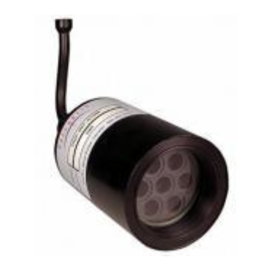
SYSTEM OCR-504 Multispectral Radiometer SECTION A - OVERVIEW Operation Manual Standard OCR-504 Figure 1 - Standard OCR-504 Configurations... - Page 7 OCR-504 Multispectral Radiometer SECTION A - OVERVIEW Operation Manual The standard OCR-504 irradiance and radiance configurations are shown in Figure 1 (dimensions are in inches). In-air and in-water weights are approximate. The housing is constructed from Acetron® GP and has a depth rating of 200 m.
-
Page 8: Deep Ocr-504Icsw
SYSTEM OCR-504 Multispectral Radiometer SECTION A - OVERVIEW Operation Manual Deep OCR-504ICSW Figure 3 - Deep OCR-504ICSW... - Page 9 SYSTEM OCR-504 Multispectral Radiometer SECTION A - OVERVIEW Operation Manual The deep version of the OCR-504ICSW is shown in Figure 3 (dimensions are in inches). The in-air and in-water weights are approximate. The housing is constructed from PEEK plastic and has a depth rating of 2000 m.
-
Page 10: Auv Ocr-504Icsw
SYSTEM OCR-504 Multispectral Radiometer SECTION A - OVERVIEW Operation Manual AUV OCR-504ICSW Figure 5 - AUV OCR-504ICSW... - Page 11 SYSTEM OCR-504 Multispectral Radiometer SECTION A - OVERVIEW Operation Manual The AUV version of the OCR-504ICSW is shown in Figure 5 (dimensions are in inches). The in-air and in-water weights are approximate. The housing is constructed from anodized aluminum and has a depth rating of 1000 m. This configuration is typically used with Autonomous Underwater Vehicles, primarily gliders.
-
Page 12: Integrated Ocr-504 Configurations
SYSTEM OCR-504 Multispectral Radiometer SECTION A - OVERVIEW Operation Manual Integrated OCR-504 Configurations Figure 6 - Integrated OCR-504 Configurations... - Page 13 A - OVERVIEW Operation Manual Several versions of the OCR-504 that have been integrated with other systems are shown in Figure 6 (dimensions are in inches). In-air and in-water weights are approximate. The three configurations shown have a depth rating of 2000 m.
-
Page 14: Specifications For Irradiance Configuration - Nominal Characteristics
SYSTEM OCR-504 Multispectral Radiometer SECTION A - OVERVIEW Operation Manual Specifications for Irradiance Configuration - Nominal Characteristics Spatial Characteristics: • Field of view: cosine response (spectrally corrected) • Collector area: 86.0 mm • Detectors: custom 17 mm silicon photodiodes Spectral Characteristics: •... -
Page 15: Specifications For Radiance Configuration - Nominal Characteristics
SYSTEM OCR-504 Multispectral Radiometer SECTION A - OVERVIEW Operation Manual Specifications for Radiance Configuration - Nominal Characteristics Spatial Characteristics: • Field of view: 10° • Detectors: custom 13 mm silicon photodiodes Spectral Characteristics: • Bandwidth range: 400-700 nm (standard - custom also available) •... -
Page 16: B - Safety & Hazards
SYSTEM OCR-504 Multispectral Radiometer SECTION B - SAFETY & HAZARDS Operation Manual B - SAFETY & HAZARDS Personal Safety • The operators should always remain aware of the cable. Any cable or line released from a ship can be dangerous. Keep a safe distance from the cable coil on deck when the instruments are being used. -
Page 17: Troubleshooting
SYSTEM OCR-504 Multispectral Radiometer SECTION B - SAFETY & HAZARDS Operation Manual Troubleshooting • While checking voltages with a multimeter, extreme care should be used to not short the probe leads. A shorted power supply or battery can output many amperes of current, potentially harming the user, starting fires, or damaging equipment. -
Page 18: C - Start Up
C - START UP Assembly Procedure REPARATION Your OCR-504 Multispectral Radiometer is a simple instrument to setup and operate. The instrument may be operated as a stand-alone device or in a networked environment as part of a larger system. Generally, requirements for operation are the same for both of these operating modes, although a networked environment may impose additional requirements. -
Page 19: Connecting The Components
Finally, ensure that the locking sleeve or locking strap is securely fastened after connection. The following is a generic step-by-step procedure for setting up your OCR-504 Multispectral Radiometer. You may use this procedure with any Sea-Bird Scientific approved interface cable: 1. -
Page 20: Network Assembly
The best way to conduct this test is to use SatView with the .sip (Sea-Bird Scientific Instrument Package) file provided with your instrument. A sip file is simply a binary file in zip format that contains a set of calibration and/or telemetry definition files. - Page 21 Otherwise, if you are experiencing any problems receiving telemetry, see section G - MAINTENANCE for information on troubleshooting your instrument. If you are still experiencing problems, contact a Sea-Bird Scientific customer service representative for assistance.
-
Page 22: D - Operation
This will continue until power is removed or the instrument is reset. Initialization Sequence Once power is applied to the OCR-504, the instrument begins a four-second window of operation called the initialization sequence. During this time, the on- board electronics are powered up, checked, and readied for operation. If the... -
Page 23: Autonomous Operation
Network operation enabled. Autonomous Operation Autonomous, or stand-alone, operation for the OCR-504 is defined as the continuous operation of the instrument outside the scope of a network. This is the default mode of operation for the instrument. Autonomous operation uses only the telemetry interface for communication and telemetry output. - Page 24 SYSTEM OCR-504 Multispectral Radiometer SECTION D - OPERATION Operation Manual you would use the <Ctrl+C> command to access the command console. To do this, press and hold the Ctrl key followed by the C key. This is the same as sending the hexadecimal equivalent byte “03”...
-
Page 25: Network Operation
Network Operation Network operation for the OCR-504 is defined as continuous operation of the instrument within the scope of a SatNet™ network. Furthermore, standard network operation means that the instrument is not operating as a Network Master device. -
Page 26: Telemetry Format
D - OPERATION Operation Manual Telemetry Format The telemetry format for the OCR-504, as with all Sea-Bird Scientific instrumentation, follows the Sea-Bird Scientific Data Format Standard. This standard defines how Sea-Bird Scientific telemetry can be generated and interpreted. For every sample taken of the instrument’s sensors, the instrument will compose and transmit one frame of telemetry containing all the relevant sensor information for that sample. -
Page 27: Binary Telemetry With Engineering Units
SYSTEM OCR-504 Multispectral Radiometer SECTION D - OPERATION Operation Manual Sample Delay A BS formatted value representing the number of milliseconds to offset the Timer value to give an accurate indication of when the frame’s sensors were sampled. A BU formatted value representing the Channel (... - Page 28 SYSTEM OCR-504 Multispectral Radiometer SECTION D - OPERATION Operation Manual Field Name Field Description Size (bytes) Instrument A unique 6 character AS formatted string denoting the start of a frame of telemetry. For irradiance sensors, the instrument string is “SATEI4”; for radiance sensors, the string is “SATER4”.
-
Page 29: Ascii Telemetry - Raw Adc Counts Only
SYSTEM OCR-504 Multispectral Radiometer SECTION D - OPERATION Operation Manual A BF formatted value (single-precision floating Channel ( point) representing the calibrated output (engineering units) from the fourth optical channel. For an irradiance sensor, the units are “uW/cm /nm”; for a radiance sensor, the units are “uW/cm... - Page 30 SYSTEM OCR-504 Multispectral Radiometer SECTION D - OPERATION Operation Manual Serial Number An AS/AI formatted string denoting the serial number of the instrument. This field combined (1 – 10 with the INSTRUMENT field uniquely identifies allowed) the instrument. This combination is known as the frame header or synchronization string.
- Page 31 An AU formatted value representing the Channel ( typical/ sampled A/D counts from the first optical channel. Tab delimiter. The Sea-Bird Scientific OPTIC2 fit type a0 A0 ( (max) coefficient for optical channel 1. Tab delimiter. The Sea-Bird Scientific OPTIC2 fit type a1 A1 (...
- Page 32 SYSTEM OCR-504 Multispectral Radiometer SECTION D - OPERATION Operation Manual Tab delimiter. 6 (max) The Sea-Bird Scientific OPTIC2 fit type Im Im ( (immersion) coefficient for optical channel 2. Tab delimiter. An AU formatted value representing the Channel ( typical/ sampled A/D counts from the third optical channel.
-
Page 33: Ascii Telemetry - Optical Data Only, In Engineering Units
SYSTEM OCR-504 Multispectral Radiometer SECTION D - OPERATION Operation Manual – O ASCII T ELEMETRY PTICAL NGINEERING NITS Data is presented as tab-delimited ASCII text. Only optical channel data is provided, in engineering units; this is known as the “short” frame type. - Page 34 SYSTEM OCR-504 Multispectral Radiometer SECTION D - OPERATION Operation Manual An AF formatted value representing the Channel ( typical/ calibrated output (engineering units) from the fourth optical channel. For an irradiance sensor, the units are “uW/cm /nm”; for a radiance sensor, the units are “uW/cm /nm/sr”.
- Page 35 SYSTEM OCR-504 Multispectral Radiometer SECTION D - OPERATION Operation Manual The Sea-Bird Scientific OPTIC2 fit type a0 A0 ( (max) coefficient for optical channel 1. Tab delimiter. The Sea-Bird Scientific OPTIC2 fit type a1 A1 ( (max) coefficient for optical channel 1.
- Page 36 SYSTEM OCR-504 Multispectral Radiometer SECTION D - OPERATION Operation Manual 6 (max) The Sea-Bird Scientific OPTIC2 fit type Im Im ( (immersion) coefficient for optical channel 3. Tab delimiter. An AF formatted value representing the Channel ( typical/ calibrated output (engineering units) from the fourth optical channel.
-
Page 37: E - Configuration
Terminal emulators are used in many applications involving serial communications, internet mail and news services, telnet and ftp services, etc. For communication with your OCR-504, you will need to make a direct connection to the serial port hosting the instrument. Connect the instrument using the RS-232 telemetry interface. - Page 38 SYSTEM OCR-504 Multispectral Radiometer SECTION E - CONFIGURATION Operation Manual The actual command prompt ends with the “$” character. The characters between the [ ] brackets provide information on the operating mode of the instrument. In the example above, “Auto” indicates that the instrument is running in autonomous mode.
-
Page 39: Reset Command
OMMAND The “id” command displays the identification banner for the instrument, as shown is the following example: Sea-Bird Scientific OCR-504 Multispectral Radiometer Copyright (C) 2011, Sea-Bird Scientific. All rights reserved. Firmware version: 5.1.0 - SatNet Type B Instrument: SATDI4 S/N: 0001 The identification banner is also part of the start-up banner, which is displayed during the initialization sequence described in section D - OPERATION. -
Page 40: Power Command
The “set” command modifies configuration parameters for the instrument. These parameters affect various aspects of the instrument’s operation and can be modified by the user to customize the instrument. For an OCR-504, if you enter a “set -?” command, the following will be displayed:... -
Page 41: Show Command
You may also use “all” as the command line parameter to show a complete list of all configuration parameters and their current values. For example, using the “show all” command on your OCR-504 would display something like this:... - Page 42 2.03852332236e-007 [2.03852e-07] a0: 1.347 [1.347] For more information on these parameters and their effect on your instrument’s operation, see section OCR-504 Configuration Parameters below. Show Calibration Coefficients A special command to display all optical channel calibration coefficients is available. Typing “show calcoeffs” will display the calibration coefficients,...
-
Page 43: Save Command
SYSTEM OCR-504 Multispectral Radiometer SECTION E - CONFIGURATION Operation Manual firmware versions (5.0.x) did not store the raw ASCII calibration string, and so only display the interpreted value. Also note that display of individual calibration coefficients (e.g. show a0ch1) is not currently supported. -
Page 44: Exit And Exit! Commands
OCR-504 Configuration Parameters This section describes, in detail, the function of each configuration parameter used by the OCR-504. The title of each section identifies the name of the parameter, as displayed by the “show” command. Also clearly identified in each section is the command line parameter keyword used in both the “set”... -
Page 45: Telemetry Baud Rate
SYSTEM OCR-504 Multispectral Radiometer SECTION E - CONFIGURATION Operation Manual The frametype parameter determines the format of the telemetry frame. When modifying this parameter with the “set” command, you must enter “binary”, “short”, or “long” as the value parameter. Please refer to the Telemetry Format section. - Page 46 Providing a maximum frame rate slower than what the instrument is capable of providing will help pace the output of each frame evenly. Generally, an OCR-504 cannot exceed a frame rate faster than 7.5 Hz, even under the best of conditions.
-
Page 47: Initialize Silent Mode
SYSTEM OCR-504 Multispectral Radiometer SECTION E - CONFIGURATION Operation Manual example, 0.5 Hz does not mean that half a frame is transmitted every second. It means that every two seconds, a frame will begin transmitting. NITIALIZE ILENT initsm Command Line Parameter: Normally, just after the instrument is powered up or reset, a start-up banner will be output on the telemetry interface during the initialization sequence. -
Page 48: Network Mode
SYSTEM OCR-504 Multispectral Radiometer SECTION E - CONFIGURATION Operation Manual ETWORK netmode Command Line Parameter: This parameter enables or disables network operation for the instrument. Although disabling this parameter will force the instrument to run autonomously, enabling it does not necessarily mean network operation will be invoked. The instrument’s operating mode is determined during the initialization sequence. -
Page 49: Optical Data Averaging Enable
SYSTEM OCR-504 Multispectral Radiometer SECTION E - CONFIGURATION Operation Manual When modifying this parameter with the “set” command, you must enter at least the first two digits of one of these baud rates as the value parameter. IMPORTANT! Make sure that each device on the network, including the Network Master, is operating with the same network baud rate. -
Page 50: Apply Calibration Coefficients Enable
This setting may be useful for synchronizing initial sampling with other instruments, or perhaps for allowing time for an optional Sea-Bird Scientific Bioshutter paddle to move out of the field of view of the OCR-504. The latency value is entered in milliseconds. -
Page 51: Immersion Coefficient
Up to 19 characters may be entered. IMPORTANT! Do not change the calibration coefficients unless you have recalibrated the sensor or instructed to do so by Sea-Bird Scientific personnel. Incorrect calibration coefficients will generate invalid data in telemetry frames generating data using engineering units. -
Page 52: F - Recovery
Operation Manual F - RECOVERY To recover the OCR-504 when it is used in water, terminate data acquisition and pull the instrument back in using the cable. You may then power down the instrument and disconnect all the cables from their corresponding components. -
Page 53: G - Maintenance
If you are experiencing problems receiving data with your data acquisition software, there may be a problem with the instrument, its configuration, or its physical setup. You can check to see if your OCR-504 is transmitting telemetry with a terminal emulator. -
Page 54: Check The Supply Voltage To The Ocr-504
SYSTEM OCR-504 Multispectral Radiometer SECTION G - MAINTENANCE Operation Manual lubricated before mating. Do not use petroleum-based lubricants. Sea-Bird ® Scientific recommends using DC-111 silicone grease (made by Dow Corning on the male pins prior to connection. Also, ensure that the connections are complete and, if applicable, the locking sleeves are secure. -
Page 55: Check Cable Continuity
SYSTEM OCR-504 Multispectral Radiometer SECTION G - MAINTENANCE Operation Manual HECK ABLE ONTINUITY Often, system problems can be traced to cable breaks or shorts. Usually, these cable failures are a result of improper handling or storage. Cable continuity can be checked as outlined below. MAKE SURE ALL CABLES ARE COMPLETELY DISCONNECTED BEFORE PERFORMING THIS TEST. -
Page 56: H - Warranty
Restrictions Warranty does not apply to products that are deemed by Sea-Bird Scientific to be damaged by misuse, abuse, accident, or modifications by the customer. The warranty is considered void if any optical or mechanical housing is opened. In addition, the warranty is void if the warranty seal is removed, broken or otherwise damaged. - Page 57 SYSTEM OCR-504 Multispectral Radiometer SECTION I - DECLARATION OF CONFORMITY Operation Manual I - DECLARATION OF CONFORMITY...
-
Page 58: J - Declaration Of Conformity
Copyright © 2017 by Sea-Bird Scientific This document contains information proprietary to Sea-Bird Scientific or to a third party to which Sea-Bird Scientific may have legal obligation to protect such information from unauthorized disclosure, use or duplication. Any disclosure, use or duplication... -
Page 59: Using Windows Hyper Terminal
You can also use it for direct communications with a serial port, which is ideal for communicating with Sea-Bird Scientific instruments. There are many types of terminal emulation programs. Most of these are suitable for this application, so you are free to use whatever terminal emulator you are comfortable with. - Page 60 SYSTEM OCR-504 Multispectral Radiometer SECTION K - APPENDIX A Operation Manual Figure 7 - Add/Remove Programs When you run HyperTerminal with a new connection, the program will ask you for connection information so it can be saved for your next session. You should...
- Page 61 SYSTEM OCR-504 Multispectral Radiometer SECTION K - APPENDIX A Operation Manual Figure 8 - HyperTerminal Connection Description Enter a name for your new connection in the space provided. The name should reflect the nature of the connections use. In this case, a good name would be “COM1 Direct”...
- Page 62 SYSTEM OCR-504 Multispectral Radiometer SECTION K - APPENDIX A Operation Manual as shown. After you make your selection, press the OK button. Finally, HyperTerminal will open a communications properties dialog box for the serial port you selected. An example dialog box, for COM1, is shown below.
- Page 63 SYSTEM OCR-504 Multispectral Radiometer SECTION K - APPENDIX A Operation Manual Figure 11 – Connection Properties dialog box In the “Emulation:” dropdown box, select ANSI as the connection’s terminal emulation mode. The other settings of the dialog box should be set as shown.
- Page 64 SYSTEM OCR-504 Multispectral Radiometer SECTION K - APPENDIX A Operation Manual Figure 12 – ASCII Setup dialog box Make sure this dialog box is setup as shown. These settings are important in maintaining proper character I/O with your instrument. You are now ready to use HyperTerminal to establish instrument communications.
Need help?
Do you have a question about the OCR-504 and is the answer not in the manual?
Questions and answers