Table of Contents
Advertisement
Quick Links
Q603-RPS
Hardware Guide
DOC-USR-0259-02
Version 1.1
November 18, 2022
This document contains proprietary and confidential information of Z3 Technology, LLC ("Z3"). This document may
not be used, reproduced, disclosed, or disseminated to anyone without the prior written approval of an authorized
representative of Z3.
Advertisement
Table of Contents

Related Manuals for Z3 Technology Q603-RPS


Summary of Contents for Z3 Technology Q603-RPS
- Page 1 Version 1.1 November 18, 2022 This document contains proprietary and confidential information of Z3 Technology, LLC ("Z3"). This document may not be used, reproduced, disclosed, or disseminated to anyone without the prior written approval of an authorized representative of Z3.
- Page 2 CONFIDENTIAL DOC-USR-0259-02 REVISION HISTORY Version Date Change Note Author 1.0.0 09/01/21 Initial Version CF/BM 1.1.0 11/18/22 Added Q603-15 in Section 4 ______________________________________________________________________________________ Z3 Technology, LLC ♦ 100 N 8 ST, STE 250 ♦ Lincoln, NE 68508-1369 USA ♦ +1.402.323.0702...
-
Page 3: Table Of Contents
Serial Console Port ..........................16 Ethernet RJ45 Port ..........................16 Composite Video Input ........................16 Genlock Indication ..........................16 4.0 30-0146 ................................17 5.0 THERMAL CONSIDERATIONS ........................19 ______________________________________________________________________________________ Z3 Technology, LLC ♦ 100 N 8 ST, STE 250 ♦ Lincoln, NE 68508-1369 USA ♦ +1.402.323.0702... - Page 4 Figure 4 Q603-RPS Connected to the FCB-ER8300 ..................8 Figure 5 Correct KEL Ribbon Cable Wiring Diagram ..................8 Figure 6 Q603-RPS Connected to a Sony Block Camera ................10 Figure 7 Correct KEL Ribbon Cable Wiring Diagram ..................11 Figure 8 Top side of 30-0104 ..........................15 Figure 9 Q603-15 PCB Layout …………………………………………………………………………………………………………….17...
-
Page 5: 1.0 Introduction
DOC-USR-0259-02 1.0 INTRODUCTION The Z3-Q603-RPS is a compact video encoder system. The system offers encoding capabilities of H.265/HEVC and H.264 video up to 4K resolutions. Together with the 30-0101 QCS603 CPU module board, the 30-0103 and 30-0104 boards form the Z3-Q603- RPS video encoder system. -
Page 6: 30-0103 Connections
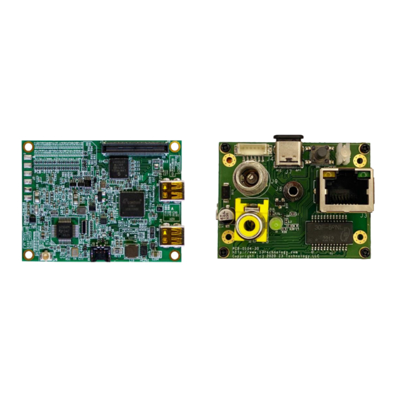
CONFIDENTIAL DOC-USR-0259-02 2.0 30-0103 30-0103 Connections The 30-0103 board has the following connections: Figure 2 Top side of 30-0103 ______________________________________________________________________________________ Z3 Technology, LLC ♦ 100 N 8 ST, STE 250 ♦ Lincoln, NE 68508-1369 USA ♦ +1.402.323.0702... -
Page 7: Connection To A Sony 4K Camera Block
Doing so is likely to cause permanent damage to the jack. Please note that LVDS camera blocks, such as the FCB-EV7520, must use jack J7 of the Q603-RPS encoder systems. Connecting the wrong camera block to the encoder will result in permanent damage to the camera and/or encoder. -
Page 8: Figure 4 Q603-Rps Connected To The Fcb-Er8300
N (N=30 in this case). Z3 Technology provides the correct cable as part of the Q603-RPS complete starter kit system. The KEL cable is also sold separately (ordering part number: CBL-0025-01). Please ONLY USE THE CABLE PROVIDED BY Z3 TECHNOLOGY to connect the Sony FCB-ER8300 to the I/F Front End PCB of the Q603 30-0103. - Page 9 This connector provides a direct connection with the Sony FCB-ER8300 block camera. Make sure to use the KEL ribbon cable provided or approved by Z3 Technology. Risk of permanent damage to the camera or encoder exists if a non-approved cable is used.
-
Page 10: Connection To The Sony Fcb-Ev7520A Camera
Using an incorrect camera is likely to permanently damage the camera body and/or encoder. Please note that the Sony 4K camera blocks, such as the FCB-ER8300, must use jack J5 of the Q603-RPS encoder systems. Connecting the wrong camera block to the encoder will result in permanent damage to the camera and/or encoder. -
Page 11: Figure 7 Correct Kel Ribbon Cable Wiring Diagram
Please note that the pin numbering of J7 on the Interface Front End PCB is opposite of that on the Sony FCB-EV7520 camera, so that it provides a straight through pass. Please only use with a KEL cable provided by ______________________________________________________________________________________ Z3 Technology, LLC ♦ 100 N 8 ST, STE 250 ♦ Lincoln, NE 68508-1369 USA ♦ +1.402.323.0702... -
Page 12: Table 2 Pcb J8 And Sony Ev7520 Pin Out
CONFIDENTIAL DOC-USR-0259-02 Z3 Technology. Using the wrong cable may cause permanent damage to the encoder system and/or camera. Signal Notes (J7) (EV7520) TXOUT4- TXOUT4+ Video output from camera to encoder TXOUT5- TXOUT5+ RESETn Camera reset signal from encoder BMODE TXOUT6-... -
Page 13: Connection To A Generic Hdmi Camera
DOC-USR-0259-02 Connection to a Generic HDMI Camera Figure 2 A Micro-HDMI port is also available on the Interface Front End PCB of the Q603-RPS 30-0103. See Top side of 30-0103 above. Connector J4 allows for an external HDMI source to be connected to the encoder. -
Page 14: Composite Input
Table 4 PCB J10 Pin Out Composite Input Figure 2 A Composite port is also available on the Interface Front End PCB of the Q603-RPS 30-0103. See Top side of 30-0103 above. Connector J6 allows for an external composite source to be connected to the encoder. -
Page 15: Rs485 And Rs232 Serial Port Header
The pin assignments of J4 are composite shown in the table below. Signal Ground RS232 RXD RS232 TXD RS485 B RS485 A +3.3V, 100mA max Table 6 J4 Pin Assignments ______________________________________________________________________________________ Z3 Technology, LLC ♦ 100 N 8 ST, STE 250 ♦ Lincoln, NE 68508-1369 USA ♦ +1.402.323.0702... -
Page 16: Usb Type C Jack
This LED indicates that a genlock-capable camera is correctly locked to a video source connected to the composite video input jack J8. ______________________________________________________________________________________ Z3 Technology, LLC ♦ 100 N 8 ST, STE 250 ♦ Lincoln, NE 68508-1369 USA ♦ +1.402.323.0702... -
Page 17: Figure 9 Q603-15 Pcb Layout
Note: The power cable used with pin connector J5 is part number CBL-0047-01. This cable can be purchased separately from Z3 Technology. ______________________________________________________________________________________ Z3 Technology, LLC ♦ 100 N 8 ST, STE 250 ♦ Lincoln, NE 68508-1369 USA ♦ +1.402.323.0702... -
Page 18: Figure 10 J2 & J7 Pinouts & Connectors
Unused UART0_RXD/GPIO3 @ 1.8V UART0_TXD/GPIO2 @ 1.8V Table 9 J3 Q603-15 pin out connectors Figure 10: Q603-15 J2 & J7 Pinout Connectors ______________________________________________________________________________________ Z3 Technology, LLC ♦ 100 N 8 ST, STE 250 ♦ Lincoln, NE 68508-1369 USA ♦ +1.402.323.0702... -
Page 19: 5.0 Thermal Considerations
This is just an example of a method to dissipate heat from the FPGA and should not be deemed sufficient or adequate for any given application. The system-level application designer must engineer a proper thermal solution that is fit for the application. ______________________________________________________________________________________ Z3 Technology, LLC ♦ 100 N 8 ST, STE 250 ♦ Lincoln, NE 68508-1369 USA ♦ +1.402.323.0702...
Need help?
Do you have a question about the Q603-RPS and is the answer not in the manual?
Questions and answers