Advertisement
Quick Links
Advertisement

Related Manuals for PCS edventures RubiQ


Summary of Contents for PCS edventures RubiQ
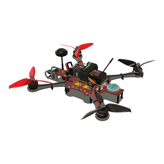
- Page 1 FLIGHT MANUAL...
- Page 2 COPYRIGHT NOTICE | Copyright © 2021 PCS Edventures, Inc. All rights reserved. Permission is hereby granted to owners of this PCS Edventures! curriculum to make photocopies of the student pages ONLY, BUT use is restricted to students attending your program ONLY. Beyond this use, any reproduction of these pages for wider dissemination or for commercial sale is strictly prohibited.
- Page 3 That’s where you come in. This guide includes your step-by- step instructions for piecing RubiQ together. Follow them in reverse to disassemble. This kit includes all the parts and tools needed for assembly, along with a few spares for any accidents along the road. Once RubiQ is built, visit rubiq.edventures.com...
- Page 4 INVENTORY To build RubiQ, you’ll need: Power Distribution Board (PDB) Lower Chassis (Qty 1) (Qty 1) Video Transmitter (VTX) FPV Camera Camera Brackets & Camera Screws (Qty 1) (Qty 1) (Qty 2) Arms CW Motors CCW Motors (Qty 4) (Qty 2)
- Page 5 (Qty 2 ea) LEGEND: EXTRA PARTS: • M3x6 Screws • M3x7 Motor Screws • M3x12 Screws • 12mm Standoffs • 25mm Standoffs FLIP REPEAT 2 TIMES • Zip Ties • Props • Prop Nuts RubiQ FLIGHT MANUAL © 2021 PCS Edventures, Inc.
-
Page 6: Power Distribution Board (Pdb)
POWER DISTRIBUTION BOARD (PDB) TOP VIEW: MICRO-USB PORT RECEIVER (RX) MOTOR CONNECTORS BATTERY CONNECTOR DIP SWITCHES TO ADJUST LED’s VIDEO (VTX) CHANNEL BOTTOM VIEW: CAMERA CONNECTOR FLIGHT CONTROLLER VIDEO TRANSMITTER (VTX) CONNECTORS RubiQ FLIGHT MANUAL © 2021 PCS Edventures, Inc. - Page 7 BUILD PLAN & CONFIGURATION GUIDE...
- Page 8 Power Distribution Board (PDB) ASSEMBLY Handle the RX antennas with care. DO NOT pull on the antennas. Too much tension will cause the wire to separate and permanently damage the RX. CAUTION RubiQ BUILD PLAN © 2021 PCS Edventures, Inc.
- Page 9 To avoid damaging the cable, do not allow the UFL to SMA Connector to twist as you tighten the nut. Do not overtighten the nut, as this will strip the threads. CAUTION RubiQ BUILD PLAN © 2021 PCS Edventures, Inc.
- Page 10 Black Cable = GND (Ground) Red Cable = 5V (5 Volt) If the wires do not match this order, disconnect both ends of the cable and reverse the orientation of the cable. RubiQ BUILD PLAN © 2021 PCS Edventures, Inc.
- Page 11 Attach the FPV camera so that the wires are near the top, close to the PDB. This will ensure that the camera is in the proper orientation. If installed incorrectly, the FPV video feed will be upside-down. CAUTION RubiQ BUILD PLAN © 2021 PCS Edventures, Inc.
- Page 12 Be sure to tighten screws until they are snug, as motors sustain intense vibration CAUTION during flight. RubiQ BUILD PLAN © 2021 PCS Edventures, Inc.
- Page 13 PARTS 25mm Standoffs M3x12 Screws ASSEMBLY black cable cable CAUTION Install all four arms as shown, with matching cables diagonal to each other to avoid erratic behavior in flight. black cable cable RubiQ BUILD PLAN © 2021 PCS Edventures, Inc.
- Page 14 PARTS Zip Ties ASSEMBLY After tightening the zip ties, carefully trim off the excess using wire cutters, scissors or a similar cutting tool. RubiQ BUILD PLAN © 2021 PCS Edventures, Inc.
- Page 15 PARTS 12mm Standoffs M3x6 Screws ASSEMBLY RubiQ BUILD PLAN © 2021 PCS Edventures, Inc.
- Page 16 PARTS Lower Chassis M3x6 Screws ASSEMBLY RubiQ BUILD PLAN © 2021 PCS Edventures, Inc.
- Page 17 PARTS Battery Plate Battery Strap M3x6 Screws ASSEMBLY RubiQ BUILD PLAN © 2021 PCS Edventures, Inc.
- Page 18 PARTS VTX Antenna ASSEMBLY Always attach the VTX antenna before connecting RubiQ to power to avoid CAUTION permanently damaging the VTX. RubiQ BUILD PLAN © 2021 PCS Edventures, Inc.
- Page 19 (see Step 6). Always make sure props are removed before connecting to the battery indoors. CAUTION Always wear safety glasses when connecting the battery. CAUTION RubiQ BUILD PLAN © 2021 PCS Edventures, Inc.
- Page 20 DO NOT wiggle the battery connector side to side when removing it from the board. Side to side motion will weaken the connection between the battery and the board. RubiQ BUILD PLAN © 2021 PCS Edventures, Inc.
-
Page 21: Configuration Guide
The compass needs to be calibrated outside as part of the pre-flight check. • RubiQ requires a GPS lock in order to arm the motors and fly. Navigation is safe indicates the GPS lock status, which defaults to red until a lock has been achieved. See Step 7 of the Pre-Flight Checklist for further information about GPS lock. -
Page 22: Preflight Checklist
GPS lock. GPS lock is achieved when the GPS module has a sufficiently strong connection to the satellites in your area. As RubiQ begins to connect to satellites, the four corners will blink green and count out the number of satellites to which RubiQ is connected. Until you have heard the beep tones that signal a successful GPS lock, you will not be able to arm the motors or fly. - Page 23 Then, arm RubiQ. While the motors are spinning, power down the radio to simulate losing connection. RubiQ should stop her motors. If the motors continue to spin, reset the failsafe and repeat this step. (see Step 3 of the Configuration Guide at rubiq.edventures.com.) Unplug the battery and attach your props.
- Page 24 4. With the hex driver, confirm that screws are still firmly attached and tighten any that feel loose. 5. Inspect RubiQ’s other physical components, including: • Arms, PDB, Frame and Camera Mount: Look for cracks or other signs of a hard impact.
- Page 25 5045BN 5045BNR Do not use the color of a propeller to determine its function. Check the coding printed on each propeller to pair CW and CCW props with the corresponding motor assembly. RubiQ BUILD PLAN © 2021 PCS Edventures, Inc.
- Page 26 ASSEMBLY 5045BN 5045BNR 5045BNR 5045BN Attach prop nuts as firmly as possible. If the props spin independently from the CAUTION motors, they aren’t tight enough. RubiQ BUILD PLAN © 2021 PCS Edventures, Inc.
-
Page 27: Field Notes
FIELD NOTES... -
Page 28: Radio Controls
Trainer Mode (SC) Flight Mode (SA) Power ARM (SD) BEEPER (SE) Disarm FLIGHT MODE (SA) SAFETY FEATURES (SB) Middle: Both OFF Position Hold Acro Mode Middle: Return to Angle Mode Launch/Home Altitude Hold RubiQ FIELD NOTES © 2021 PCS Edventures, Inc. -
Page 29: Flight Modes
Keep in mind that if you lose connection to your radio, your drone will drop out of the sky, so never fly over people, buildings or property that could be damaged. RubiQ FIELD NOTES © 2021 PCS Edventures, Inc. - Page 30 For an extra smooth flight, enable Position Hold shortly after lift-off. SB: both OFF SA: Angle Mode BEGINNERS: Start in Angle Mode. SB: both OFF SA: Acro Mode EXPERIENCED PILOTS: Start in Acro Mode. RubiQ FIELD NOTES © 2021 PCS Edventures, Inc.
- Page 31 Green GPS light (number of blinks = number of satellites detected) ARM: Green Arm State lights (disarmed, meaning the Blue Arm State lights (armed, meaning the motors will not turn on) motors are turned on) RubiQ FIELD NOTES © 2021 PCS Edventures, Inc.
- Page 32 NOTE: The default warning cell voltage is set to 3.5V to account for the dip that can occur when the drone draws heavily on the battery during flight. When RubiQ lands and you plug in the battery to recharge, you should notice that the cells show a voltage higher than 3.5V.
- Page 33 FPV BANDS AND FREQUENCY CHANNELS RubiQ’s VTX transmits on Band A, which is the following set of frequencies: Boscam A/TBS 5.725 5.745 5.765 5.785 5.805 5.825 5.845 5.865 GHz The position of the dip switches on Rubi’s PCB sets the frequency channel for the video feed from the camera.
- Page 34 6 months from the date of shipment. Within the period of this warranty, PCS Edventures will repair or replace, free of charge, any part proving defective in material or workmanship.
- Page 35 V: 01/13/21...
- Page 36 edventures.com...
Need help?
Do you have a question about the RubiQ and is the answer not in the manual?
Questions and answers