Table of Contents
Advertisement
Advertisement
Table of Contents

Subscribe to Our Youtube Channel
Related Manuals for PCS edventures RubiQ


Summary of Contents for PCS edventures RubiQ
- Page 2 COPYRIGHT NOTICE | Copyright © 2020 PCS Edventures, Inc. All rights reserved. Permission is hereby granted to owners of this PCS Edventures! curriculum to make photocopies of the student pages ONLY, BUT use is restricted to students attending your program ONLY. Beyond this use, any reproduction of these pages for wider dissemination or for commercial sale is strictly prohibited.
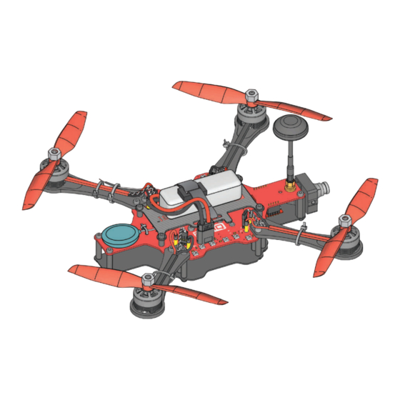
- Page 3 That’s where you come in. This guide includes your step-by- step instructions for piecing RubiQ together. Follow them in reverse to disassemble. This kit includes all the parts and tools needed for assembly, along with a few spares for any accidents along the road. Once RubiQ is built, visit rubiq.edventures.com...
- Page 4 INVENTORY To build RubiQ, you’ll need: Power Distribution Board (PDB) Lower Chassis (Qty 1) (Qty 1) TX Antenna Video Transmitter (VTX) UFL to SMA Cable, (Qty1) (Qty 1) Lock Washer & Lock Nut (Qty 1) FPV Camera Assembly Arm/Motor/ESC Assemblies - CW...
- Page 5 Zip Tie (Qty 28) (Qty 12) (Qty 5) LEGEND: EXTRA PARTS: • M3x6 Screws ROTATE • M3x12 Screws • 12mm Standoffs • 25mm Standoffs • Zip Ties FLIP REPEAT 2 TIMES • Props RubiQ FLIGHT MANUAL © 2020 PCS Edventures, Inc.
-
Page 6: Power Distribution Board
POWER DISTRIBUTION BOARD TOP VIEW: BATTERY CONNECTOR ESC CABLE CONNECTOR PINS DIPSWITCH MOTOR CABLE CONNECTORS RECEIVER (RX) MICRO-USB PORT LED’s BOTTOM VIEW: FLIGHT CONTROLLER VIDEO TRANSMITTER CAMERA CABLE (VTX) CONNECTOR CONNECTOR PINS RubiQ FLIGHT MANUAL © 2020 PCS Edventures, Inc. -
Page 7: Important Notes
Connect cables as shown, with the black wire to GND, red to 5V and yellow to Video. From the bottom view of Rubi, GND is the pin closest to the center of the drone. Failure to do so may cause irreparable damage to RubiQ. FIRE RISK... - Page 8 Connect cables as shown, with the red motor cables connecting to V+ and black to GND. The white ESC wire connect to SIG and the black wire to GND. Failure to do so may cause irreparable damage to RubiQ. FIRE RISK...
- Page 9 BUILD PLAN & CONFIGURATION GUIDE...
- Page 10 PARTS 12mm M3 x 6 ASSEMBLY Attach all screws as firmly as possible to keep the frame stable during flight. CAUTION RubiQ BUILD PLAN © 2020 PCS Edventures, Inc.
- Page 11 Connect cables as shown, with the black wire to GND, red to 5V and yellow to Video. From the bottom view of Rubi, GND is the pin closest to the center of the drone. Failure to do so may cause irreparable damage to RubiQ. FIRE RISK...
- Page 12 Install all four arms as shown, with matching colored cables diagonal to each other to avoid erratic behavior in flight. Wait until STEP 7 to plug in the cables to avoid bending the pins. RubiQ BUILD PLAN © 2020 PCS Edventures, Inc.
- Page 13 PARTS ASSEMBLY Leave some slack when securing the receiver’s antenna. Too much tension will cause CAUTION the wire to separate, rendering your receiver inoperable. RubiQ BUILD PLAN © 2020 PCS Edventures, Inc.
- Page 14 CAUTION If the nut is tightened correctly, there will be a few metal threads visible after the antenna is attached. Orient the VTX so each pin slides into its own connector. CAUTION RubiQ BUILD PLAN © 2020 PCS Edventures, Inc.
- Page 15 PARTS M3 x 6 ASSEMBLY RubiQ BUILD PLAN © 2020 PCS Edventures, Inc.
-
Page 16: Motor Cables
SIG = Signal - white wire GND = Ground - black wire The orientation and casing-type of the ESC connector in this diagram may differ from your RubiQ drone. Depending on the batch of motors, the smooth plastic casing of the ESC connector may face in (as shown here) or may face out. - Page 17 PARTS M3 x 6 ASSEMBLY Attach battery plate with the hole directly above the receiver to facilitate radio binding. CAUTION RubiQ BUILD PLAN © 2020 PCS Edventures, Inc.
- Page 18 Make sure hole in battery plate is directly above the receiver (RX). (see Step 8) CAUTION Always remove props before connecting the battery while indoors. CAUTION Always wear safety glasses when connecting battery. CAUTION RubiQ FLIGHT MANUAL © 2020 PCS Edventures, Inc.
- Page 19 DO NOT wiggle the battery connector side to side when removing it from the board. Side to side motion will weaken the connection between the battery and the board. RubiQ BUILD PLAN © 2020 PCS Edventures, Inc.
-
Page 20: Configuration Guide
• The compass needs to be calibrated outside as part of the pre-flight check. • RubiQ comes with GPS lock enabled, which means she won’t indicate that navigation is safe or be able to fly without first connecting to seven satellites, something she can only do while out at the flight field. -
Page 21: Preflight Checklist
Make sure the drone and the radio are bound. Power on the radio controller and connect the battery to RubiQ. Look for a solid light of RubiQ’s RX or flip the beeper switch to test the connection. Make sure all radio controller switches face away from you. - Page 22 Then, arm RubiQ. While the motors are spinning, power down the radio to simulate losing connection. RubiQ should stop her motors. If the motors continue to spin, reset the failsafe and repeat this step. (see Step 3 of the Configuration Guide at rubiq.edventures.com.) Unplug the battery and attach your props.
- Page 23 4. With the hex driver, confirm that screws are still firmly attached and tighten any that feel loose. 5. Inspect RubiQ’s other physical components, including: • Arms, PDB, Frame and Camera Mount: Look for cracks or other signs of a hard impact.
- Page 24 Pusher (R) Normal Propeller Propeller 5045BNR 5045BN Pusher (R) Normal Propeller Propeller 5045BN 5045BNR Check the coding printed on each propeller to pair CW and CCW props with the corresponding motor assembly. RubiQ BUILD PLAN © 2020 PCS Edventures, Inc.
- Page 25 ASSEMBLY 5045BNR 5045BN 5045BN 5045BNR Attach prop nuts as firmly as possible. If the props spin independently from the CAUTION motors, they aren’t tight enough. RubiQ BUILD PLAN © 2020 PCS Edventures, Inc.
-
Page 26: Radio Controls
Hold/Return to Home (SA) Power BEEPER (SF) ARM (SG) Middle: no function Disarm FLIGHT MODE (SE) Both Acro Mode features: Off Middle: Middle: Angle Mode Position Hold Return to Altitude Hold Launch/Home RubiQ FIELD NOTES © 2020 PCS Edventures, Inc. -
Page 27: Flight Modes
Position Hold and Return to Home, can only be activated after she has been armed. Failsafe: If RubiQ loses connection to the radio, either because she’s flown out of radio range or because the radio loses power and shuts down, the default failsafe is for the drone to drop out of the sky. To make it easier to find, the drone will steadily beep until a radio connection is restored. - Page 28 For an extra smooth flight, enable Position Hold shortly after lift-off. SE: Altitude Hold SA: both SE: Angle Mode features off BEGINNERS: Start in Angle Mode. SE: Acro Mode SA: both features off EXPERIENCED PILOTS: Start in Acro Mode. RubiQ FIELD NOTES © 2020 PCS Edventures, Inc.
- Page 29 Green GPS light (number of blinks = number of satellites detected) ARM: Green Arm State lights (disarmed, meaning the Blue Arm State lights (armed, meaning the motors will not turn on) motors are turned on) RubiQ FIELD NOTES © 2020 PCS Edventures, Inc.
- Page 30 NOTE: The default warning cell voltage is to set 3.5V to account for the dip that can occur when the drone draws heavily on the battery during flight. When RubiQ lands and you plug the battery in to recharge, you may notice that the cells show a voltage higher than 3.5V.
- Page 31 FPV BANDS AND FREQUENCY CHANNELS RubiQ’s VTX transmits on Band A, which is the following set of frequencies: Boscam A/TBS 5.725 5.745 5.765 5.785 5.805 5.825 5.845 5.865 GHz The position of the dip switches on Rubi’s PCB sets the frequency channel for the video feed from the camera.
- Page 32 6 months from the date of shipment. Within the period of this warranty, PCS Edventures will repair or replace, free of charge, any part proving defective in material or workmanship.
- Page 33 V: 03/04/20...
Need help?
Do you have a question about the RubiQ and is the answer not in the manual?
Questions and answers