Table of Contents
Advertisement
Quick Links
Advertisement
Table of Contents

Related Manuals for CSC RX1E


Summary of Contents for CSC RX1E
- Page 2 Preface The electric motorcycle can be used on road only and by one driver. The user should read the user’s manual carefully prior to using the product. The user shall have a proper command of basic operation functions, usage method and other common sense for the model. The data, technical specifications and performance parameters labeled in the manual are compiled based on the latest status.
- Page 3 It indicates a potential danger that may cause damages to the motorcycle if any misoperation. The most efficient service information is available for faster warranty service and more understandable instructions. CSC Motorcycles Address: 1331 W Foothill Blvd, Azusa, CA Customer service hotline: 1-800-884-4173...
-
Page 4: Table Of Contents
Table of Contents Preface Security Information Matters Needing Attention Vehicle Identification Number (VIN) and Engine Number Motorcycle Introduction Electric Switch USB, Charging Port Instrument Indicator Left handle switch Right handle switch Control part Load limit Inspection before driving Starting and Driving Operation Inspection and Adjustment after the Running-in Period Safe Driving Guidance Periodic Maintenance Schedule... - Page 5 Instruction to User Please read this manual carefully before using the electric vehicle! Caution ! Danger After unpacking, please check the attached accessories and Strictly abide by traffic regulations and drive safely. various materials according to the packing list. Users who don't have motor vehicle driver’s license should not This model is a single-rider vehicle.
-
Page 6: Vehicle Identification Number (Vin) And Engine Number
Instruction to User Vehicle Identification Number (VIN) and Engine Number Vehicle identification number (VIN), engine number and vehicle certificate are used to apply for driving license and motorcycle account. 1.The vehicle identification 2. The vehicle nameplate is 3. The motor number is engraved number (VIN) is printed on the riveted on the left frame riser. -
Page 7: Motorcycle Introduction
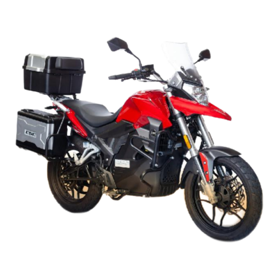
Instruction to User Motorcycle Introduction 1. Rear view mirror 2. Left steering handle 3. Left control switch 4. Instrument assembly 5. Right control switch 6. Throttle 7. Ignition lock 8. Storage box lock... - Page 8 Instruction to User Motorcycle Introduction 1. Rear armrest 2. Seat cushion 3. Storage box 4. Headlight 5. Rear wheel 6. Rear disc brake 7. Motor 8. Rear brake pedal 9. Front shock absorber 10. Front wheel...
- Page 9 Instruction to User Motorcycle Introduction 1. Front wheel 2. Front brake 3. Engine guard 4. Charging interface 5. Kickstand 6. Center stand 7. Drive belt 8. Taillight 9. Drive pulley 10. Rear wheel...
-
Page 10: Electric Switch
Instruction to User Electric Switch Name Functional Description Turn the key to the position “ ” and turn on 1. How to turn on the circuit to start the motor. the switch Turn the key to the position “ ”. Do not 2. -
Page 11: Usb, Charging Port
Instruction to User USB, Charging Port Name Direction for Use 1.USB port The USB interface is located on the right side of the instrument panel and connected to the mobile phone charging line for mobile phone charging. 2. Charging The charging port for the motorcycle interface battery is located on the left side of the motorcycle, under the body panel that... -
Page 12: Instrument Indicator
Instruction to User Instrument Indicator... - Page 13 Instruction to User Name Functional Description Name Functional Description 11. ABS fault light When starting, the ABS fault light is on and it will be 1. Speedometer Displays the running speed of the vehicle. off if the speed is above 20km / h. When the left turn indicator is on, “...
-
Page 14: Left Handle Switch
Instruction to User Left handle switch The main functions of the left handle switch are as follows: Name Direction for Use 1. Passing light To flash your high beams at night when passing another vehicle, press this “PASS” switch. switch. To activate cruise control, press this button while 2. -
Page 15: Right Handle Switch
Instruction to User Right handle switch The main functions of the right handle switch are as follows: Name Direction for Use When the vehicle is parked, the indicator 1.Pmodekey light on the instrument is on; When the user presses this key, the indicator light will be off and the vehicle can be started. -
Page 16: Control Part
Instruction to User Control part The brakes of this model are equipped with front and rear disc brakes, and the braking performance is reliable. Braking is related to personal and property safety and must be regularly and correctly adjusted and maintained to achieve the goal of safe driving. - Page 17 Instruction to User Control part Name Direction for Use 3. Seat lock Insert the key and turn clockwise to open the seat cushion. 4. Locker lock Insert the key and turn clockwise to turn on the locker light under the seat cushion.
-
Page 18: Load Limit
Instruction to User Load limit This model is made for one rider and one passenger only. Do not exceed this limit or you could compromise the safety and stability of the vehicle. Factory-determined maximum payload of the finished vehicle : 330 lbs. The maximum load of the locker : 11 lbs. Danger Follow these instructions carefully. -
Page 19: Inspection Before Driving
Operation Guide Inspection before driving Before driving, check in accordance with the following requirements to ensure users' safe driving and successful driving. Items Check Remark Depending on how far and how Battery Check if the battery has enough power. often you ride your motorcycle, you should perform three levels of Drive device Check whether the controller and drive motor are working properly. -
Page 20: Starting And Driving Operation
Operation Guide Starting and Driving Operation Turn the switch lock to the position“ ” and turn on the ignition of the electric vehicle. Hold the front and rear brake levers to prevent the motorcycle from sliding. Please use the left blinker to warn pedestrians and cars when exiting your spot. - Page 21 Operation Guide Inspection and Adjustment after the Breaking-in Period When you get a new motorcycle, you need to take care of it during the break-in period (the first 500 miles on the odometer). How well you break in your new motorcycle affects how long it will last. The break-in period is when the new parts of your motorcycle get used to working together and become smoother and more efficient.
-
Page 22: Safe Driving Guidance
Operation Guide Safe driving guidance 1. Precautions for driving up and down ramps When driving on mountain roads with twists and turns and undulating slopes, the driving speed shall be adjusted according to the actual situation to avoid motor overload. 2. - Page 23 Operation Guide Safe driving guidance ③ When you ride down steep or long hills, don’t keep your foot on the brake pedal or brake too often, because the brake will get too hot and won’t work well. You need to brake according to the situation. When you ride on rainy, wet and slippery roads, don’t ride too fast.
-
Page 24: Periodic Maintenance Schedule
Maintenance Periodic maintenance schedule Maintenan Odometer miles ce times 500 miles 2,000 miles 4,000 miles 7,500 miles Remark Maintenance items ※Controller Check Check Check Control cable Cleaning Cleaning Cleaning Cleaning Brake handle Adjustment Adjustment Adjustment Adjustment ※Battery The user charges in accordance with the mileage ※Brake shoe Check Check... -
Page 25: Maintenance Requirements
Maintenance Maintenance requirements In the process of driving an electric vehicle, various parts will have different degrees of looseness and mechanical wear and tear, it is necessary to carry out correct periodic maintenance of the vehicle, in order to extend the service life of the vehicle, reduce maintenance costs, to achieve the goal of safe driving. -
Page 26: Use And Maintenance Of Charger
Maintenance Use and maintenance of charger Chargers are an important part of electric vehicles, and the quality of chargers affects the service life of batteries a lot. The charger is mainly composed of rectification filter, high voltage switch, voltage exchange, constant voltage and charging control. This charger features a trickle mode to prevent overcharging. -
Page 27: Use And Maintenance Of Battery
Use and maintenance of battery The battery of the RX1E is installed near the front of the frame. The battery has the advantages of large capacity, small self discharge, high energy, long service life, safety and reliability. It is an ideal power battery. Please read the instructions carefully before using the battery. -
Page 28: Maintenance Of Drive Motor
Maintenance Maintenance of drive motor This vehicle features a permanent magnet DC motor mounted at the center, which achieves an efficiency of over 92%. This design offers several benefits, such as enhanced hill-climbing capability, high speed, low current draw, extended range, and smooth coasting. -
Page 29: Inspection And Adjustment Of Brakes
Maintenance Inspection and adjustment of brakes Inspection of hydraulic brake 1. Make sure the brake lever has the correct amount of free play according to the manufacturer’s specifications. If the brake lever travel cannot be adjusted properly, it means that the brake pads are worn beyond the service limit and need to be replaced. 2. -
Page 30: Cleaning And Storage
Maintenance Cleaning and storage 1. Cleaning of electric vehicles (1) Do not use high-pressure water to clean your electric motorcycle. This could cause damage or malfunction of the internal electronic components and circuits due to water intrusion. (2) After cleaning, wipe the surface of the motorcycle with a clean cotton cloth or clean towel. (3) Apply wax on the surface of pained parts and anti-rust oil on the chrome plated surfaces. -
Page 31: Common Fault Diagnosis And Troubleshooting Methods
Maintenance Common Fault Diagnosis and Troubleshooting Methods I. Fault: motor does not turn. Fault causes and solutions: 1. Fault cause: the battery voltage is too low, causing the controller to be under-voltage protected; Solution: charge the battery. 2. Fault cause: the battery voltage is too high, which causes the controller to be in overvoltage protection state; Solutions: a. - Page 32 Maintenance Solution: replace the controller. Malfunction cause: the motor is damaged; Such as turn-to-turn short circuit of the motor winding, large interference of Hall signal output, etc. . Solution: this kind of fault is difficult to be measured, detected and processed by multimeter, so replacement method can be used to replace the new motor to see if the problem still exists, and if the problem is solved, the motor is faulty.
- Page 33 Maintenance Solution: replace the controller. IX. Fault: Sometimes, after applying the brake while riding, the throttle does not respond. Failure cause: the lever fails or is damaged after being used for a long time; Solution: replace the brake switch. X. Fault: short cruising range. Failure cause analysis: The range of the bike depends on various factors, some of which are determined by the manufacturer: the efficiency and performance of the motor, the capacity and lifespan of the battery;...
- Page 34 Maintenance Fault code display Faulty component Fault name Fault code Faulty Fault name Fault code component Battery system b Discharge monomer undervoltage fault 3 b310 Controller overvoltage failure P301 BMS discharge over temperature fault 1 b119 Controller undervoltage failure P302 BMS discharge over temperature fault 2 b219 Controller overcurrent failure...
- Page 35 Maintenance Faulty component Fault name Fault code Faulty component Fault name Fault code BMS internal communication failure b333 Input overvoltage protection 1 C107 BMS internal MOS failure or relay failure b307 Input overvoltage protection 2 C207 Charging monomer battery undervoltage fault level 1 b140 Input overvoltage protection 3 C307...
-
Page 36: Technical Specifications And Performance Parameters
Technical Specifications and Performance Parameters Items ZS8000D-2 Specifications / Parameters Outline dimension L × W × H 82.2×34×47.4in/2090×865×1205mm Wheelbase 55.5 in/1400mm Minimum ground clearance 6in/150mm Complete vehicle curb mass 436.5lbs/198kg Maximum capacity 331lbs/150kg Maximum speed 75mph/120km/h 112 miles – 62 miles/180km-100km Driving range (working condition method / isokinetic method) Motor specification and model... -
Page 37: Electrical Schematic Diagram
Electrical Schematic Diagram Electrical Schematic Diagram 1. Power supply system 2. DC-DC converter and auxiliary 3. Power drive system 4. Control switches and 5.Instrument system lamps Horn Rear brake switch Left turn signal Flash relay Left turn signal indicator Position lamp Right turn signal Instrument lighting lamp Right turn signal indicator... - Page 38 All rights reserved First edition in April 2023...
Need help?
Do you have a question about the RX1E and is the answer not in the manual?
Questions and answers