Table of Contents
Advertisement
SG250 Owner's and Service Manual
www.CSCMotorcycles.com
Contents
Foreword ....................................................................................................................................................... 4
Caution and Warning Symbols ...................................................................................................................... 4
Section 1: Owner's Manual .......................................................................................................................... 5
General Motorcycle Safety Guidance ........................................................................................................... 5
Inspections Before Riding ............................................................................................................................. 6
Motorcycle Specifications ............................................................................................................................. 6
Motorcycle Description ................................................................................................................................. 8
Controls ......................................................................................................................................................... 9
Ignition Lock and Fork Lock ........................................................................................................................... 9
Fork Lock ....................................................................................................................................................... 9
Instruments ................................................................................................................................................... 9
Left and Right Handlebar Switchgear ........................................................................................................... 9
Fuel, Fuel Tank, Filler Cap, and Petcock ...................................................................................................... 10
Choke .......................................................................................................................................................... 11
Load Limits .................................................................................................................................................. 11
Tool Kit ........................................................................................................................................................ 12
Engine Break-In Procedure ......................................................................................................................... 12
Starting the Motorcycle .............................................................................................................................. 12
Operating the Motorcycle ........................................................................................................................... 13
Cleaning the Motorcycle ............................................................................................................................. 13
Storing the Motorcycle ............................................................................................................................... 14
Section 2: Service Manual ......................................................................................................................... 16
Maintenance Cautions and Warnings ......................................................................................................... 16
Component Cleaning................................................................................................................................... 16
Parts Inspection .......................................................................................................................................... 17
Maintenance Adjustments .......................................................................................................................... 17
Recommended Tools .................................................................................................................................. 17
Adjustment Specifications .......................................................................................................................... 17
Motorcycle Maintenance Schedule ............................................................................................................ 18
Torque Values ............................................................................................................................................. 18
Unpacking ................................................................................................................................................... 19
Inspection .................................................................................................................................................... 19
Frame and Body .......................................................................................................................................... 19
Brakes .......................................................................................................................................................... 20
Master Cylinder Location ............................................................................................................................ 20
Front Brake Pad Inspection and Replacement ............................................................................................ 21
Rear Brake Pad Inspection and Replacement ............................................................................................. 22
Front Brake Rotor Inspection ...................................................................................................................... 23
Flushing and Replacing the Brake Fluid ...................................................................................................... 24
Bleeding the Brakes .................................................................................................................................... 24
Brake Troubleshooting ................................................................................................................................ 24
Power Transmission .................................................................................................................................... 25
Chain Drive System ..................................................................................................................................... 25
1
Advertisement
Table of Contents
Troubleshooting

Related Manuals for CSC SG250


Summary of Contents for CSC SG250
-
Page 1: Table Of Contents
SG250 Owner’s and Service Manual www.CSCMotorcycles.com Contents Foreword ............................... 4 Caution and Warning Symbols ........................4 Section 1: Owner’s Manual .......................... 5 General Motorcycle Safety Guidance ......................5 Inspections Before Riding ..........................6 Motorcycle Specifications ..........................6 Motorcycle Description ..........................8 Controls ................................. - Page 2 SG250 Owner’s and Service Manual www.CSCMotorcycles.com Chain Lubrication ............................25 Chain Adjustment ............................25 Sprocket and Chain Inspection ........................27 Chain Drive Troubleshooting ........................28 Clutch Maintenance ............................ 28 Clutch Cable Installation and Adjustment ....................29 Clutch Replacement ............................ 30 Clutch Troubleshooting ..........................
- Page 3 Thank you for purchasing this CSC San Gabriel 250 motorcycle. The SG250 is a great motorcycle and we are very proud of it. The SG250 is easy to maintain, it’s reliable, and it’s fun. You’ve made a wise purchase decision.
-
Page 4: Foreword
Reproduction of the CSC SG250 Owner’s and Service Manual or posting it online without CSC’s permission is expressly prohibited. If you have any questions, please contact CSC Motorcycles by calling us at 909 445 0900 or via email at info@CSCMotorcycles.com. -
Page 5: Section 1: Owner's Manual
SG250 Owner’s and Service Manual www.CSCMotorcycles.com Section 1: Owner’s Manual General Motorcycle Safety Guidance Warning! Do not attempt to ride this motorcycle on public roads if you do not have a motorcycle license. Warning! Do not attempt to ride this motorcycle if you do not know how to ride a motorcycle. -
Page 6: Inspections Before Riding
SG250 Owner’s and Service Manual www.CSCMotorcycles.com Inspections Before Riding Before riding your motorcycle, you should check the following: Both tires are appropriately inflated. Neither tire has nails nor other foreign objects embedded in the tread or the sidewall. - Page 7 SG250 Owner’s and Service Manual www.CSCMotorcycles.com Bore x Stroke 66.5mm x 66.2mm Displacement 229.9 cc Compression Ratio 9.6:1 Horsepower 16.1 @ 7000 rpm Torque 13.5 ft-lb Oil Type 10W 40, motorcycle type Oil Capacity 1.3 quart Starting Electric and kick...
-
Page 8: Motorcycle Description
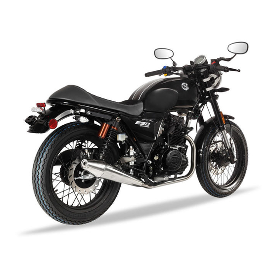
SG250 Owner’s and Service Manual www.CSCMotorcycles.com Motorcycle Description The CSC SG250 motorcycle is a 250cc street motorcycle. The motorcycle has a single-cylinder, 4-stroke, air-cooled engine and a 5-speed transmission. Major components are identified in the photographs below. SG250 Right Side View... -
Page 9: Controls
The ignition switch also operates the parking light. If you need additional keys, CSC stocks the key blanks for the SG250 motorcycle. Please call us at 909 445 0900 if you need to make additional keys for your motorcycle. -
Page 10: Fuel, Fuel Tank, Filler Cap, And Petcock
Fuel, Fuel Tank, Filler Cap, and Petcock The SG250 fuel tank holds 4.0 gallons of fuel. Use 87 octane or higher fuel. The fuel petcock is located on left side of the tank. Turn the petcock to the OFF position when you are not riding the motorcycle. -
Page 11: Choke
Do not attempt to actuate the choke lever while riding the motorcycle. Warning! Load Limits The SG250 motorcycle weighs 273 lbs. The gross vehicle weight rating is 573 lbs. Warning! Do not overload or unevenly load the motorcycle or the handling will be adversely affected. -
Page 12: Tool Kit
SG250 Owner’s and Service Manual www.CSCMotorcycles.com Tool Kit The SG250 includes a tool kit stored in a container on the right side of the motorcycle beneath the battery. Pull up on the tab beneath the tool kit cover and the cover will rotate up, providing access to the tool kit. -
Page 13: Operating The Motorcycle
SG250 Owner’s and Service Manual www.CSCMotorcycles.com After the engine starts, allow it to warm for at least one minute. As the engine warms, open the choke an intermediate position and then after the engine has warmed to the fully open position (the choke lever should be all the way forward). -
Page 14: Storing The Motorcycle
When riding the motorcycle after cleaning it, actuate the brakes to make sure they have not been degraded as a result of cleaning the motorcycle. CSC stocks numerous cleaning and lubrication products; please call us at 909 445 0900 to order these items. - Page 15 SG250 Owner’s and Service Manual www.CSCMotorcycles.com CSC stocks all the items described above. Please call us at 909 445 0900 to order any of the items described above.
-
Page 16: Section 2: Service Manual
When you maintain or repair the motorcycle, please use original components and parts, accessories, lubricating oil and other materials that are made or recognized by CSC Motorcycles. Caution! If you use any parts or components other than those recommended by CSC, it may adversely affect the performance, reliability, stability, or warranty of your motorcycle. -
Page 17: Parts Inspection
Tire pressure should be maintained at 40 psi for the front tire and 36 psi for the rear tire. Recommended Tools The CSC SG250 motorcycle includes a basic tool kit that is stored under the battery. These tools are suitable for emergency repairs only. CSC sells custom tool kits with professional grade tools; please contact us at 909 445 0900 to order tools. -
Page 18: Motorcycle Maintenance Schedule
SG250 Owner’s and Service Manual www.CSCMotorcycles.com Motorcycle Maintenance Schedule Maintenance Odometer (miles) Times 5,000 7,500 10,000 12,500 15,000 2,500 miles miles miles miles miles Maintenance miles miles Item Fuel system Fuel filter Air cleaner element Spark plug gap Valve lash... -
Page 19: Unpacking
When the motorcycle is delivered, check the condition of the delivered crate. If there are any anomalies, stop and call CSC at 909 445 0900. Check the VIN numbers on the exterior of the crate. Compare these numbers to the documentation delivered to you prior to the motorcycle’s arrival. If the numbers don’t match, stop and call CSC at 909 445 0900. -
Page 20: Brakes
Impact Deformation Compromised Replace the rear rack placement of items Brakes This section of the SG250 Owner’s and Service Manual covers the following topics: Master cylinder locations Inspecting and replacing the brake pads Inspecting and replacing the brake disk ... -
Page 21: Front Brake Pad Inspection And Replacement
Note that one of the brake pads has a wear groove machined into the pad surface. When the pad is worn such that the wear groove is no longer visible, replace both pads with new pads. CSC stocks these pads, so call us at 909 445 0900 if you need to order a pair. -
Page 22: Rear Brake Pad Inspection And Replacement
Rear Brake Pad Inspection and Replacement The SG250 uses a mechanically-actuated drum brake in the rear. It is mechanically linked to the rear brake pedal with a steel rod. The amount of free play in the rear brake pedal before the rear brake starts to engage is adjusted via a threaded nut on the rear of the steel rod. -
Page 23: Front Brake Rotor Inspection
CSC stocks replacement brake shoes, so call us at 909 445 0900 if you need to order a pair. Note that it is normal for the front brake pads to wear out much more quickly than the rear brake shoes. -
Page 24: Flushing And Replacing The Brake Fluid
Loctited in place at the factory and it is easy to strip the Allen drive socket (we recommend heating the head of the bolt first to soften the adhesive). CSC stocks replacement rotors and Allen bolts; if you need a new rotor please call us at 909 445 0900. -
Page 25: Power Transmission
This section of the Owner’s and Service Manual addresses adjusting the SG250 motorcycle’s chain and aligning the rear wheel. You don’t have to get the rear wheel off the ground to adjust the SG250’s chain. Adjusting the chain on a motorcycle consists of two jobs: Adjusting chain tension and aligning the rear wheel. - Page 26 SG250 Owner’s and Service Manual www.CSCMotorcycles.com You should check the chain adjustment during your motorcycle’s first scheduled maintenance and at every scheduled maintenance thereafter. The biggest adjustment will occur at the first service interval, because chains do most of their stretching in their first several hundred miles of use. When the chain is properly adjusted, it should have about 15mm (or 3/5 of an inch) slack at its midpoint.
-
Page 27: Sprocket And Chain Inspection
Lube the chain every time it is adjusted. You can use either a wax-based or an oil-based chain lube; CSC stocks both types. You can call us at 909 445 0900 if you need chain lube. -
Page 28: Chain Drive Troubleshooting
The SG250 motorcycle chain does not have a master link. When you need to replace the original equipment chain on your motorcycle, you have to cut it off. -
Page 29: Clutch Cable Installation And Adjustment
SG250 Owner’s and Service Manual www.CSCMotorcycles.com Clutch Cable Installation and Adjustment Route the cable from the handlebar (without attaching it yet) to the engine. Note that there is a loop welded on the left front frame downtube through which you should route the clutch cable. -
Page 30: Clutch Replacement
Note that the photos in this portion of the SG250 Service Manual show the TT250 engine. The TT250 and SG250 engines are identical. - Page 31 SG250 Owner’s and Service Manual www.CSCMotorcycles.com Drain the engine oil. See the Oil Change section of the Service Manual for instruction on how to do this. Disconnect the rear brake lever from the rear master cylinder by removing the cotter pin and pulling the shaft out. This will allow rotating the rear brake lever out of the way to allow removing the right engine case.
- Page 32 SG250 Owner’s and Service Manual www.CSCMotorcycles.com Disconnect the clutch cable at the engine end. Remove the 13 10mm bolts securing the right engine cover to the engine. Tap the right engine cover lightly with a soft mallet to loosen Remove the right engine cover.
- Page 33 SG250 Owner’s and Service Manual www.CSCMotorcycles.com Remove the clutch actuation rod and bushing. Remove the clutch throwout bearing. If this bearing is worn or does not operate smoothly, replace it with a new bearing.
- Page 34 SG250 Owner’s and Service Manual www.CSCMotorcycles.com Remove the six clutch bolts in an even pattern by unscrewing each bolt a few turns at a time. Do this in a crisscross pattern to allow the clutch hub to back out evenly.
- Page 35 SG250 Owner’s and Service Manual www.CSCMotorcycles.com This is the rounded edge. To remove the rest of the clutch components, it is necessary to remove the centrifugal oil cleaner. Unscrew the three Phillips head screws on the centrifugal oil cleaner. Remove the centrifugal oil cleaner cover.
- Page 36 SG250 Owner’s and Service Manual www.CSCMotorcycles.com The inner portion of the centrifugal oil cleaner is secured by a castellated nut. This nut is shown by the lower red arrow on the right in the photo. Use a castellated nut driver like the one shown here to remove the nut.
- Page 37 The fiber plates are the outer plates on both sides of the clutch assembly. The plates alternate (fiber, steel, fiber, steel, etc.). CSC stocks the clutch plates and the clutch springs. Please call us at 909 445 0900 if you need these components.
- Page 38 SG250 Owner’s and Service Manual www.CSCMotorcycles.com Inspect the clutch inner basket for any discontinuities in the notches on which the clutch plates translate. If the clutch inner basket has surface discontinuities or excessive wear, replace it. Similarly inspect the clutch outer basket for any surface discontinuities or excessive wear.
-
Page 39: Clutch Troubleshooting
5 ft-lbs. Torque the engine cover bolts to 15 ft-lbs. Torque the kick start lever bolt to 35 ft- lbs. Torque the centrifugal oil cleaner castellated nut to 60 ft-lbs. After installing all components, adjust the clutch as explained in the SG250 Clutch Adjustment section of this manual. Clutch Troubleshooting... -
Page 40: Suspension
If you wish to use a higher viscosity fork oil to stiffen the forks, please call CSC at 909 445 0900 to discuss which oil will best meet your needs. - Page 41 SG250 Owner’s and Service Manual www.CSCMotorcycles.com Loosen any wiring or cable clamps on the fork lower triple tee. Remove the reflector. Inserting a wrench under the lower triple tee cover, loosen the lower triple tee pinch bolt. Loosen the upper triple tee pinch blot.
- Page 42 SG250 Owner’s and Service Manual www.CSCMotorcycles.com Slide the fork leg out of the motorcycle. Slide the fork gator off the lower folk leg. Using a flat bladed screwdriver, gently pry the seal retainer out of its groove in the lower fork leg.
- Page 43 SG250 Owner’s and Service Manual www.CSCMotorcycles.com Remove the Allen bolt from the lower fork leg. Turn the fork leg right side up and drain the oil from the fork. Note that each fork leg contains approximately 160cc of oil Secure the lower fork leg in a vice, taking care not to mar the finish.
-
Page 44: Swingarm And Rear Suspension
If the seal(s) leak due to age-induced degradation, you should to replace the seals on both fork legs. Please call CSC at 909 445 0900 for a discussion on which oil best suits your needs and to order replacement oil. - Page 45 SG250 Owner’s and Service Manual www.CSCMotorcycles.com Remove the nut and bolt that attaches the rear shock absorber to the swingarm. Rotate the lower portion of the rear shock absorber to clear the swingarm mounting bracket, and remove the bushing from the rear shock absorber.
- Page 46 SG250 Owner’s and Service Manual www.CSCMotorcycles.com Remove the swingarm from the motorcycle frame. Remove the dust caps that fit between the frame and the swingarm. The next steps involve re-greasing (lubricating) the swingarm pivot points. We use Maxima waterproof grease, which is a great lubricant.
-
Page 47: Swingarm And Rear Suspension Troubleshooting
SG250 Owner’s and Service Manual www.CSCMotorcycles.com Apply grease to the rear shock absorber bushing. Insert the rear shock absorber bushing and apply grease to the exterior exposed edge of the bushing. Assembly is the reverse of disassembly. Torque the shock absorber nut and bolt to 25 ft-lbs. There is no torque specification for the swingarm pivot axle nuts. -
Page 48: Steering System
If you hear or feel clicking in the front end, it is likely you need to adjust the steering stem bearings. The photos in this section of the SG250 Service Manual show the TT250 motorcycle. The SG250 and TT250 motorcycles are similar in design. - Page 49 SG250 Owner’s and Service Manual www.CSCMotorcycles.com Loosen both the left and right pinch bolts. Loosen the steering stem bolt. You don’t need to remove the handlebars to do this. Use a spanner to either tighten or loosen the steering stem adjustor nut.
-
Page 50: Steering System Troubleshooting
Replace steering column Wheels and Tires The SG250 uses a 2.50x17 aluminum-rimmed wire wheel on the front of the motorcycle, and a 3.00x17 aluminum-rimmed wire wheel on the rear of the motorcycle. Both the front and rear wheels use inner tubes. -
Page 51: Front Wheel Removal
SG250 Owner’s and Service Manual www.CSCMotorcycles.com Front Wheel Removal Support the motorcycle such that the front wheel is off the ground. Warning! Make sure the motorcycle is adequately supported. If it is not, it could tip over, injuring you and damaging the motorcycle. -
Page 52: Rear Wheel Removal
SG250 Owner’s and Service Manual www.CSCMotorcycles.com While removing the front wheel, remove the speedometer wheel from the front wheel. Note that the front hub has drive tabs to engage the speedometer drive unit. The slots that engage the tabs on the speedometer drive unit. - Page 53 SG250 Owner’s and Service Manual www.CSCMotorcycles.com Remove the rear brake torque rod cotter pin and nut, and disconnect the rear brake torque rod from the rear brake. Remove the rear brake actuation rod nut and rotate the brake actuator to disconnect the actuation rod from the rear brake.
- Page 54 SG250 Owner’s and Service Manual www.CSCMotorcycles.com Remove the left axle adjustor. Note that the axle adjustor has an integral washer on one side. It faces out, away from the wheel. Remove the right axle adjustor. Note that the axle adjustor has an integral washer on one side.
-
Page 55: Wheel And Tire Inspection
SG250 Owner’s and Service Manual www.CSCMotorcycles.com Rear wheel installation is the reverse of removal. The rear axle nut should be torqued to 35 ft-lbs. When the rear wheel is installed, the chain should be adjusted and the rear wheel should be aligned. - Page 56 Note that the photos shown in this section of the Service Manual are photos of the RX3 motorcycle. The concepts are the same for the SG250 motorcycle. Remove the wheel with the flat tire in accordance with the instructions for doing so in this Service Manual.
- Page 57 After accomplishing the above, inflate the tire and to seat it on the rim. CSC advises keeping a patch kit, a tire repair kit, and a source of compressed air with you, especially if you ride in remote locations. If you need these items, please call CSC at 909 445 0900.
-
Page 58: Engine
The SG250 takes 1.3 quarts of 10W-40 motorcycle oil. The SG250 has two oil cleaning devices. One is the strainer (it is addressed in this section of the Owner’s and Service Manual), and it should be removed and cleaned with each oil change. The other cleaning device is the centrifugal oil cleaner, which is located inside the right engine crankcase cover. - Page 59 SG250 Owner’s and Service Manual www.CSCMotorcycles.com Remove the dipstick from the engine. Remove the oil drain plug underneath the engine and allow the oil to drain. Hold the bike in the vertical position so all the oil drains. The oil drain plug takes a 17mm wrench or socket.
- Page 60 SG250 Owner’s and Service Manual www.CSCMotorcycles.com When the oil strainer cap is removed, there will be a spring inside of it, as shown below. Usually, the oil strainer remains in the engine when the oil strainer cap and spring are removed. You’ll have to reach into the engine with a pick or a screwdriver to get the oil strainer out of the engine.
- Page 61 SG250 Owner’s and Service Manual www.CSCMotorcycles.com Pour 1.2 liters of oil into the oil fill port on the right side of the motorcycle. 1.2 liters is about 1.3 quarts. The best way to get the right amount of oil in the engine is to pour in a quart, and then pour the last 0.3 quarts in at a slow rate keeping an eye on...
-
Page 62: Spark Plug Removal And Installation
10,000 miles or more often if the motorcycle exhibits symptoms consistent with spark plug failure (missing under load, no spark across the electrode, etc.). Note that the photos in this section of the Service Manual show the TT250 motorcycle. The SG250 and the TT250 use the same engine. - Page 63 SG250 Owner’s and Service Manual www.CSCMotorcycles.com photos in this section of the Service Manual show the TT250 motorcycle. The SG250 and the TT250 use the same engine. You’ll need the following tools for this operation: A pair of pliers ...
- Page 64 Most of the work in adjusting the valves is associated with just getting access to the adjustors. The adjustment operation (once we have access) takes only a few minutes. When you adjust the valves, you have to start with a cold engine. Let your SG250 cool down completely.
- Page 65 SG250 Owner’s and Service Manual www.CSCMotorcycles.com The valve cover is attached to the cylinder head by three 10mm bolts. Note that there is a fourth 10mm bolt on top of the valve cover (it’s the one in the photo below just beneath and partially behind the hose).
- Page 66 SG250 Owner’s and Service Manual www.CSCMotorcycles.com The valve cover seals to the cylinder head with an o-ring type seal. Place the valve cover where this seal will not be contaminated by dirt or debris. Prior to reinstalling the valve cover (after you have adjusted the valves), apply a light coat of motor oil to the rubber seal.
- Page 67 SG250 Owner’s and Service Manual www.CSCMotorcycles.com After you have removed the cover, you will see a 14mm bolt head. By placing a socket wrench on this bolt head, you will be able to rotate the engine (it’s why we removed the spark plug).
- Page 68 SG250 Owner’s and Service Manual www.CSCMotorcycles.com The next mark is a scribe line with an F. This shows when the spark plug fires. We’re not interested in that mark, either, for the valve adjustment operation. It’s mentioned here for reference only.
-
Page 69: Carburetor
Note that the photos shown here are from the TT250 motorcycle. The engine is the same as the SG250 motorcycle. The SG250 uses a Keima slide carburetor. It will be much easier to gain access to the carburetor if the fuel tank is removed. - Page 70 SG250 Owner’s and Service Manual www.CSCMotorcycles.com Loosen the Phillips head screw securing the airbox inlet to the carburetor. Detach it from the carburetor. Unscrew the carburetor slide assembly cap and remove the carburetor slide assembly from the carburetor. Pull the slide out of the carburetor body.
- Page 71 SG250 Owner’s and Service Manual www.CSCMotorcycles.com It will be easier to access the left side carburetor mounting nut if you first detach the rear brake master cylinder. Pull the carburetor away from the engine. Detach the vent hose such that you can move the carburetor to a clean work area.
- Page 72 SG250 Owner’s and Service Manual www.CSCMotorcycles.com Place the float bowl aside. At this point, when you invert the carburetor you can see the float, the float valve, the main jet, the slow jet, and the idle jet. The float pivots on the float pivot shaft to operate the float...
- Page 73 SG250 Owner’s and Service Manual www.CSCMotorcycles.com Gently push the float pivot shaft out of the carburetor body. Lift the float and the float valve from the carburetor body. Take care not to drop the float valve; it will fall off of the float when the float is tilted.
- Page 74 SG250 Owner’s and Service Manual www.CSCMotorcycles.com The main jet is in a brass carrier. It’s likely the entire carrier will unscrew when you unscrew the main jet. You can then unscrew the main jet if you secure the main jet carrier with an 8mm wrench.
- Page 75 SG250 Owner’s and Service Manual www.CSCMotorcycles.com Remove the idle jet. There will be a spring, a flat metal washer, and an o-ring beneath the idle jet. Carefully remove these from the carburetor body if they do not come out with the idle jet.
- Page 76 SG250 Owner’s and Service Manual www.CSCMotorcycles.com Clean all three jets using a suitable cleaning solvent and a jet cleaning tool to assure all passageways are open. We stock these items; please call us at 909 445 0900 if you need them.
- Page 77 SG250 Owner’s and Service Manual www.CSCMotorcycles.com Remove the o-rings from the float bowl and the carburetor body. Clean the carburetor interior and exterior surfaces using a suitable solvent. Use a q-tip to clean the interior of the float valve body.
- Page 78 SG250 Owner’s and Service Manual www.CSCMotorcycles.com This is what the seat should look like viewed from the carburetor bore. After the bushing is in place, install the main jet carrier and lightly tighten it. Do not overtighten it. Install the main jet and lightly tighten it with a flat head screwdriver.
- Page 79 SG250 Owner’s and Service Manual www.CSCMotorcycles.com Lowering the float valve into the carburetor body. Guide the float pivot shaft through the carburetor body tangs’ drilled pivot points and the float. Reinstall the O-rings on the float body and the carburetor body.
-
Page 80: Air Filter Replacement
909 445 0900 and we will ship these items to you. You should check your SG250 air filter every 2500 miles. If it is dirty or clogged, it will reduce the motorcycle’s performance and you should replace it. You should check the air filter more often if you ride in dusty or offroad conditions. -
Page 81: Exhaust System
Assembly is the reverse of disassembly. Exhaust System This section of the Owner’s and Service Manual addresses the SG250 exhaust system. This section of the SG250 Service Manual shows the TT250 motorcycle. The SG250 and TT250 exhaust systems are similar. - Page 82 SG250 Owner’s and Service Manual www.CSCMotorcycles.com Remove the acorn nuts. Slide the exhaust header flange away from the cylinder head Loosen the 10mm bolt securing the exhaust header-to- muffler clamp. Remove the 10mm bolt securing the forward end of the muffler to the motorcycle frame.
-
Page 83: Engine Troubleshooting
Remove the mesh gasket between the exhaust header and the muffler. Assembly is the reverse of disassembly. CSC stocks all SG250 exhaust system parts. Please call us at 909 445 0900 if you require replacement parts. Engine Troubleshooting Item... -
Page 84: Fuel System
SG250 Owner’s and Service Manual www.CSCMotorcycles.com Item Symptom Cause Vehicle Effect Maintenance Action Starter Difficult starting Clogged air Difficult to start engine Check air filter, check filter, charging circuit, check carburetor not valves; adjust/correct as adjusted required correctly, valves too... - Page 85 Remove and replace the fuel filter. If you need replacement fuel filters, please contact CSC at 909 445 0900. To gain access to the components located underneath the fuel tank, you will need to remove the fuel tank. Start by removing the left and right body panels.
- Page 86 If you wish to remove the fuel tank, unplug the fuel tank sending unit wiring harness. CSC stocks all fuel system components. Please contact us at 909 445 0900 if you need any parts.
-
Page 87: Fuel System Troubleshooting
SG250 Owner’s and Service Manual www.CSCMotorcycles.com Fuel System Troubleshooting Item Symptom Cause Vehicle Effect Maintenance Action Fuel tank Rusty tank body Water intrusion Fuel leakage Repair or replace the tank Fuel supply impeded Fuel cap vent Starting failure, engine Clean air vent... -
Page 88: Control Cables
Control Cables The CSC SG250 uses one control cable for the throttle, and one for the clutch. The pictures shown here are for the TT250. The SG250 and the TT250 are similar in design. The throttle cable should be adjusted such that there it has 2 to 5 degrees of free rotation before the throttle is actuated. - Page 89 SG250 Owner’s and Service Manual www.CSCMotorcycles.com The horn is located on the frame immediately behind the forks. It is accessible without removing the fuel tank. The fuel sensor sending unit is located beneath the fuel tank. The connector from the fuel tank’s fuel gage sending unit to the fuel gage is underneath the tank.
- Page 90 SG250 Owner’s and Service Manual www.CSCMotorcycles.com As you can see from the photo, red is positive, and green is ground. Throughout the motorcycle, wires with green insulation are ground wires. The rectifier and the CDI are underneath the fuel tank. If this component is not working, the battery will not charge properly or it may overcharge and boil over.
- Page 91 SG250 Owner’s and Service Manual www.CSCMotorcycles.com The starter solenoid is located on the right side of the motorcycle just to the rear of the battery. It closes when commanded to do so to send power to the starter motor. The motorcycle’s only electrical fuse is located in a carrier alongside the battery.
- Page 92 SG250 Owner’s and Service Manual www.CSCMotorcycles.com Another connector bundle is located on the left side of the engine just above the transmission. These are the connectors inside the shroud shown above. The flasher and its connector are located immediately behind the battery.
-
Page 93: Battery
Connectors and harnesses for the controls are located beneath the fuel tank. This SG250 Owner’s and Service Manual provides a wiring diagram, which can be used in conjunction with the above photos when troubleshooting any electrical problems. Battery This section of the Owner’s and Service Manual addresses SG250 battery maintenance. - Page 94 SG250 Owner’s and Service Manual www.CSCMotorcycles.com battery when it won’t hold a charge. In this section of the Owner’s and Service Manual, we’re showing everything with the battery removed from the motorcycle (which is the way we prefer to work on the battery), but everything seen in this section can be done with the battery in the bike.
-
Page 95: Lighting And Turn Signals
If it’s less than 12.8 volts, replace the battery. If you need a new battery, CSC stocks all of the parts for your SG250. Please call us at 909 445 0900. - Page 96 SG250 Owner’s and Service Manual www.CSCMotorcycles.com Unscrew the two Phillips head screws at the bottom of the headlight nacelle. Tight the headlight and its trim ring forward, out of the headlight nacelle. Unplug the headlight. Remove the bulb from the reflector.
-
Page 97: Charging System
You might have a charging system problem if the battery is dead or the bike is hard to start. It’s more likely this is just a battery problem, so the first thing to do is to check the battery (see the SG250 battery maintenance section of this Manual). - Page 98 The photos shown here are from the TT250 motorcycle; the SG250 is similar. Place a drip pan beneath the engine, as oil will escape from the engine during this operation, and remove the gear shift lever with a 10mm wrench.
- Page 99 SG250 Owner’s and Service Manual www.CSCMotorcycles.com Remove the countershaft sprocket cover. Disconnect the stator harness. Remove the starter motor transfer gear cover. Remove the starter transfer gears. Note their orientation; the smaller gear is closest to the starter motor. Note that there are small shims on either side of the gear cluster;...
-
Page 100: Starting System
60 N-m. Torque the engine cover mounting and countershaft cover bolts to 9 N- m. Apply Loctite to the stator mounting bolts and torque the stator mounting bolts to 9 N-m. Starting System The SG250 has both a kickstarter and an electric starter. This section of the Operation and... - Page 101 Maintenance Manual addresses the SG250 electric start system. If your SG250 does not start when you press the starter button, the first thing you should check is the engine kill switch to make sure it is in the run position.
- Page 102 If the starter solenoid closes, use a multimeter and check to see if electrical energy is reaching the starter motor. Note that the photos shown here are from the TT250; the SG250 motorcycle is similar. If the starter motor is receiving electrical energy but does not crank, the problem is most likely the starter motor.
- Page 103 SG250 Owner’s and Service Manual www.CSCMotorcycles.com Remove the countershaft sprocket cover. Remove the charging circuit harness retention clip. Disconnect the charging circuit connector plug. Unbolt the 8mm bolt inside the starter motor transfer case. Gently remove the left engine crankcase cover.
- Page 104 SG250 Owner’s and Service Manual www.CSCMotorcycles.com Check the two drive gears that interface with the starter motor gear transfer gears and the engine start drive gear. Note that the gear cluster has thin shims on either side; take care not to lose these. If either is damaged, replace the transfer gears.
-
Page 105: Electrical System Troubleshooting
SG250 Owner’s and Service Manual www.CSCMotorcycles.com After removing the rotor, remove the engine start drive gear if it is damaged. To do so, you must remove the small Woodruff key that indexes the engine start drive gear to the crankshaft. Gently tap the Woodruff key out with a screwdriver and a hammer. - Page 106 SG250 Owner’s and Service Manual www.CSCMotorcycles.com Item Symptom Cause Vehicle Effect Maintenance Action Charging Cannot start or operate Check charging system system defect motorcycle. output to isolate defective component, replace defective component Leaks Cracked battery Leaking battery acid Check battery case for case, battery cracking;...
-
Page 107: Electrical Schematic
SG250 Owner’s and Service Manual www.CSCMotorcycles.com Electrical Schematic... -
Page 108: Appendix A - Service Checklists
SG250 Owner’s and Service Manual www.CSCMotorcycles.com Appendix A - Service Checklists 500-Mile New Motorcycle First Service Customer Name: License: Odometer; Repair Order No: Date: Technician: Service Item Completion Comments Change engine oil and filter Check/adjust intake and exhaust valves to 0.07mm... - Page 109 SG250 Owner’s and Service Manual www.CSCMotorcycles.com 2500-Mile Motorcycle Service Customer Name: License: Odometer; Repair Order No: Date: Technician: Service Item Completion Comments Change engine oil and filter, clean screens Check engine mounts; tighter as required Inspect air filter, clean or replace as necessary...
- Page 110 SG250 Owner’s and Service Manual www.CSCMotorcycles.com 5000-Mile Motorcycle Service Customer Name: License: Odometer; Repair Order No: Date: Technician: Service Item Completion Comments Change engine oil and filter, clean screens Check engine mounts; tighter as required Check intake/exhaust valve timing; adjust gap to 0.07mm...
- Page 111 SG250 Owner’s and Service Manual www.CSCMotorcycles.com Annual Motorcycle Service Customer Name: License: Odometer; Repair Order No: Date: Technician: Service Item Completion Comments Change engine oil and filter Change brake fluid front and rear Check throttle cable for smooth operation Check/adjust tire pressure (32 psi front and rear)
Need help?
Do you have a question about the SG250 and is the answer not in the manual?
Questions and answers