Table of Contents
Advertisement
Quick Links
General Description
The MIC2786/7/8/9 are low-current, ultra-small, push-
button reset supervisors with long set-up delays. All the
devices feature two manual reset inputs and two reset
outputs. The devices initiate a reset for the reset timeout
period when the /MR0 and /MR1 inputs are asserted low
for a period longer than the set-up delay.
In addition, the MIC2786 and MIC2787 feature an
integrated supply voltage monitor. Reset will be
asserted for the reset timeout delay once the supply
voltage increases above the rising threshold voltage.
The MIC2786 and MIC2788 feature integrated pull-up
resistors on the /MR0 and /MR1 inputs, while the
MIC2787
and
MIC2789
resistors. The PDY input pin selects between a 2s, 4s,
or 6s set-up period. Factory-programmed reset timeout
periods of 140ms (minimum) and 240ms (minimum) are
available.
The MIC2788-XYMT EV Evaluation Board comes with
the MIC2788-XYMT (t
RESET
also be used to evaluate the MIC2786, MIC2787 and
MIC2789. Contact Micrel or an authorized distributor for
samples and simply replace the chip on board, as these
devices are all pin-to-pin compatible.
For the MIC2787 and MIC2789, positions R1 and R2 will
need to be populated with 100kΩ resistors.
Datasheets and support documentation can be found on
Micrel's web site at: www.micrel.com.
Requirements
The MIC2788 Evaluation Board requires only a single
power supply that is capable of delivering greater than
1mA at a voltage range of 1.5V to 5.5V. An oscilloscope
can be used to view and measure the inputs and
outputs.
Precautions
There is no reverse input protection on this board. While
connecting supplies and signals ensure that correct
polarities are observed. The maximum operating VIN is
rated at 5.5V.
MLF and MicroLeadFrame are trademarks of Amkor Technology, Inc.
Micrel Inc. • 2180 Fortune Drive • San Jose, CA 95131 • USA • tel +1 (408) 944-0800 • fax + 1 (408) 474-1000 •
May 2012
require
external
pull-up
= 140ms) installed, but it can
MIC2786/7/8/9 Evaluation Board
Push-Button Reset IC
Getting Started
1. VIN Supplies
Connect a supply to the VIN and GND terminals, paying
careful attention to the polarity and the supply range
(1.5V ≤ VIN ≤ 5.5V). An ammeter may be placed
between the input supply and the VIN terminal to the
evaluation board. Ensure that the supply voltage is
monitored at the VIN terminal. The ammeter can reduce
the voltage supplied to the input.
2. Connect PDY Pin (J5)
Connect the programmable delay input (PDY) pin
according to desired set-up delay. Leave PDY pin open
for setup-delay of 2s, connect to GND for set-up delay of
4s or connect to VIN for set-up delay of 6s.
3. Monitor Inputs and Outputs
Monitor the inputs (/MR0 and /MR1) and outputs (/RST
and RSTP) with an oscilloscope.
4. Turn on the Power
Turn on the power supply. Observe that /MR0, /MR1
and /RST are pulled up to VIN while RSTP remains at
0V.
5. Press Push-Buttons
Press push-button inputs /MR0 and /MR1 and observe
/RST and RSTP outputs. Keeping the push-button
inputs asserted low for the programmed setup delay
time initiates one reset output pulse for the reset timeout
delay period.
Ordering Information
Part Number
Description
MIC2788-XYMT EV
MIC2788 Evaluation Board
http://www.micrel.com
M9999-052412
Advertisement
Table of Contents

Related Manuals for Micrel MIC2786


Summary of Contents for Micrel MIC2786
- Page 1 5.5V. MLF and MicroLeadFrame are trademarks of Amkor Technology, Inc. Micrel Inc. • 2180 Fortune Drive • San Jose, CA 95131 • USA • tel +1 (408) 944-0800 • fax + 1 (408) 474-1000 • http://www.micrel.com May 2012...
- Page 2 MIC2786/7/8/9 Evaluation Board Evaluation Board Features See the MIC2788/MIC2789 datasheet for detailed explanations of these functions. For detailed operation of the MIC2786/MIC2787 see the MIC2786/MIC2787 datasheet. Programmable Delay Pin (PDY) Use Table 1 to program the PDY pin for desired set- up delay time.
- Page 3 Micrel, Inc. MIC2786/7/8/9 Evaluation Board Evaluation Board Schematic Bill of Materials Item Part Number Manufacturer Description Qty. GRM188R71C104KA01D Murata 0.1µF, 16V capacitor, X7R, 0603 CRCW0603100KJNEA Vishay 100k, 5% resistor, 0603 R1, R2 MIC2788-XYMT Micrel, Inc. Push-Button Reset IC Notes: Murata: www.murata.com.
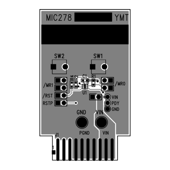
- Page 4 Micrel, Inc. MIC2786/7/8/9 Evaluation Board PCB Layout Recommendations Top Silkscreen Copper Layer 1 M9999-052412 May 2012...
- Page 5 Micrel, Inc. MIC2786/7/8/9 Evaluation Board PCB Layout Recommendations (Continued) Copper Layer 2 Bottom Silkscreen M9999-052412 May 2012...
- Page 6 (b) support or sustain life, and whose failure to perform can be reasonably expected to result in a significant injury to the user. A Purchaser’s use or sale of Micrel Products for use in life support appliances, devices or systems is a Purchaser’s own risk and Purchaser agrees to fully indemnify Micrel for any damages resulting from such use or sale.
Need help?
Do you have a question about the MIC2786 and is the answer not in the manual?
Questions and answers