Advertisement
Quick Links
General Description
The
MIC7401
is
configurable, power-management IC (PMIC) featuring five
synchronous buck regulators, one boost regulator, and
2
high-speed I
C interface with an internal EEPROM and
micro-power shutdown. The device offers two distinct
modes of operation "standby mode" and "normal mode".
In normal mode, the programmable switching converters
can be configured to support a variety of features,
including start-up sequencing, timing, soft-start ramp,
output voltage levels, current-limit levels, and output
discharge for each channel.
In standby mode the PMIC can configured in a low power
state by either disabling an output or by changing the
output voltage to a lower level. Independent exit from
standby
mode
can
communication or the external STBY pin.
The initial settings of the evaluation board are:
Input: 2.4V to 5.5V
Output 1: 1.8V/0.8A
Output 2: 1.1V/0.5A
Output 3: 1.8V/0.5A
Datasheets and support documentation are available on
Micrel's web site at: www.micrel.com.
Evaluation Board
D
HyperLight Load is a registered trademark of Micrel, Inc.
Micrel Inc. • 2180 Fortune Drive • San Jose, CA 95131 • USA • tel +1 (408) 944-0800 • fax + 1 (408) 474-1000 •
July 21, 2015
a
powerful,
highly-integrated,
be
achieved
either
Output 4: 1.05V/3.0A
Output 5: 1.25V/1.0A
Output 6: 12V/0.2A
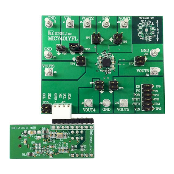
B
G
A
E
C
MIC7401 Evaluation Board
Configurable PMIC, Five-Channel
Buck Regulator plus One-Boost with
HyperLight Load
Requirements
The MIC7401 evaluation board requires only a single
power supply with 5A (minimum) current capability. The
output load can either be an active (electronic) or passive
(resistive) load.
Precautions
The MIC7401 evaluation board does not have reverse
polarity protection. Applying a negative voltage to the VIN
and GND terminals can damage the device. The maximum
operating rating for V
could damage the device.
Ordering Information
Part Number
2
by
I
C
MIC7401EV
MICUSB
A) INPUT VOLTAGE
B) OUTPUT VOLTAGES
C) USB DONGLE CONNECTOR
2
D) I
C SDA AND SCL
2
E) I
C PULL-UP TO VIN
F)
STATUS AND CONTROL BIT HEADER
F
G) ENABLE
®
2
, I
C Control and Enable
is 5.5V. Exceeding 5.5V on the VIN
IN
Description
MIC7401 Evaluation Board
USB Dongle
http://www.micrel.com
Revision 1.0
Advertisement

Subscribe to Our Youtube Channel
Related Manuals for Micrel MIC7401


Summary of Contents for Micrel MIC7401
- Page 1 G) ENABLE HyperLight Load is a registered trademark of Micrel, Inc. Micrel Inc. • 2180 Fortune Drive • San Jose, CA 95131 • USA • tel +1 (408) 944-0800 • fax + 1 (408) 474-1000 • http://www.micrel.com July 21, 2015...
- Page 2 “Target OK” will appear on the bottom of the GUI window indicating it is operational. Before configuring the MIC7401, the GUI needs to be set for direct editing. To do this click on Link > Link Mode > Directing Editing. Now it is time to program the MIC7401.
- Page 3 As the voltage 905305. level in the GUI changes, the output of the MIC7401 will also change. The “On” check box is the ON/OFF control for the regulators. If checked, the regulator is enabled.
- Page 4 MIC7401 Evaluation Board Functional Description The MIC7401 is one of the industry’s most-advanced The MIC7401 has a current-mode boost regulator that can PMIC devices designed for solid state drives (SSD) on the deliver up to 200mA of output current and only consumes market today.
-
Page 5: Table Of Contents
Micrel, Inc. MIC7401 Evaluation Board Table 1. Buck Outputs Default Soft-Start Time (DEFAULT) Figure 7 shows the output of Buck 1 ramping up cleanly, starting from 0.15V to its final 1.1V value. RAMP (µs) (µs) OUT1 OUT2 OUT3 1.05 OUT4 VOUT5 1.25... - Page 6 Micrel, Inc. MIC7401 Evaluation Board The ramp time is determined by Equation 2: Programmable Boost Soft-Start Control The boost soft-start time is divided into two parts as shown Figure 10. T1 is a fixed 367µs delay starting from when −...
-
Page 7: Vout5
Boost Digital Voltage Control (DVC) The boost output control works the same way as the buck, The MIC7401 buck regulators have high-side current limiting that can be varied by a 4-bit code. If the regulator except that the voltage steps are 200mV (see Figure 12). - Page 8 Micrel, Inc. MIC7401 Evaluation Board During start-up sequencing if Output 1 is still shorted, Global Power-Good Pin Outputs 2 through 4 will come up normally. Once an The global power-good output indicates that all the outputs overcurrent condition is sensed, then the fault register is are above the 91% limit after the power-up sequence is set to “1”...
- Page 9 MIC7401 Evaluation Board Power-Up Sequencing Global Enable Pin When power is first applied to the MIC7401, all I²C When the enable pin rises above the enable threshold registers are loaded with their default values from the voltage, the MIC7401 enters its start-up sequence.
- Page 10 PORUP register. The POR output goes low without delay if goes high without delay if the PGOOD_MASK[6] bit is set AVIN falls below the lower UVLO threshold set by the to “0”. PORDN register. Figure 17. MIC7401 Power-Up/Down July 21, 2015 Revision 1.0...
- Page 11 An I²C write command to the STBY_CTRL_REG register There is a 100µs STBY deglitch time that eliminates or the STBY pin can be used to set the MIC7401 into nuisance tripping, allowing all regulators to enable at the stand-by mode. The standby (STBY) pin provides a same time and ramp up with their programmed ramp rates.
- Page 12 Micrel, Inc. MIC7401 Evaluation Board Evaluation Board Schematic VOUT3 150µF 0Ω PGND 499kΩ 2.2µF 100kΩ PVIN2 PVIN1 10µF 10µF 2.2µH 2.2µH OUT2 OUT1 1.1V/0.5A 1.8V/0.8A OUT2 OUT1 22µF 22µF PGND PGND2 PGND1 PGND MIC7401 PVIN3 PVIN6 10µF 2.2µH PMEG4002 2.2µH OUT3 1.8V/0.5A...
- Page 13 Micrel, Inc. MIC7401 Evaluation Board Bill of Materials Item Part Number Manufacturer Description Qty. CL05A225KO5NQNC Samsung 2.2µF/16V, Ceramic, X5R, 0402, 0.8mm, ±10% C2, C7, C9, C11, CL10A106MO8NQNC Samsung 10µF/16V, Ceramic, X5R, 0603, 0.8mm, ±20% C4, C6 CL21A106KAYNNNE Samsung 10µF/25V, Ceramic, X5R, 0805, 1.25mm, ±20%...
- Page 14 Micrel, Inc. MIC7401 Evaluation Board PCB Layout Recommendations Evaluation Board Top Layer − Power Component Placement Evaluation Board Top Layer − Layer 1 (Power Routing Layer) July 21, 2015 Revision 1.0...
- Page 15 Micrel, Inc. MIC7401 Evaluation Board PCB Layout Recommendations (Continued) Evaluation Board Top Layer − Layer 1 (Power Routing Layer) Evaluation Board Layer 2 (Ground Plane) July 21, 2015 Revision 1.0...
- Page 16 Micrel, Inc. MIC7401 Evaluation Board PCB Layout Recommendations (Continued) Evaluation Board Top Layer − Layer 3 (Signal Routing Layer) Evaluation Board Layer 4 (Ground Plane) July 21, 2015 Revision 1.0...
- Page 17 Micrel, Inc. MIC7401 Evaluation Board PCB Layout Recommendations (Continued) Evaluation Board Layer − Layer 5 (V Plane) Evaluation Board Bottom Later − Layer 6 (Ground Plane) July 21, 2015 Revision 1.0...
- Page 18 (b) support or sustain life, and whose failure to perform can be reasonably expected to result in a significant injury to the user. A Purchaser’s use or sale of Micrel Products for use in life support appliances, devices or systems is a Purchaser’s own risk and Purchaser agrees to fully indemnify Micrel for any damages resulting from such use or sale.
- Page 19 Mouser Electronics Authorized Distributor Click to View Pricing, Inventory, Delivery & Lifecycle Information: Microchip ADM00812...
Need help?
Do you have a question about the MIC7401 and is the answer not in the manual?
Questions and answers