Table of Contents
Advertisement
Quick Links
Advertisement
Table of Contents

Related Manuals for Ricoh DU5040


Summary of Contents for Ricoh DU5040
- Page 1 Decurl Unit DU5040 Machine Code: D3A4 Field Service Manual November, 2014...
-
Page 3: Safety, Conventions, Trademarks
Safety, Conventions, Trademarks Conventions Common Terms This is a list of symbols and abbreviations used in this manual. Symbol What it means Screw Connector E-ring Clip ring Harness clamp Flexible Film Cable Junction Gate Leading Edge of paper Long Edge Feed Short Edge Feed Trailing Edge of paper [A] Short Edge Feed (SEF) -
Page 4: Warnings, Cautions, Notes
Warnings, Cautions, Notes In this manual, the following important symbols and notations are used. • A Warning indicates a potentially hazardous situation. Failure to obey a Warning could result in death or serious injury. • A Caution indicates a potentially hazardous situation. Failure to obey a Caution could result in minor or moderate injury or damage to the machine or other property. -
Page 5: Table Of Contents
TABLE OF CONTENTS Safety, Conventions, Trademarks........................1 Conventions..............................1 Common Terms............................1 Warnings, Cautions, Notes...........................2 Responsibilities of the Customer Engineer....................2 Reference Material for Maintenance....................2 The Aim of Anti-tip Components and Precautions..................2 1. Replacement and Adjustment Decurl Unit and Electrical Components......................5 Decurl Unit.............................. -
Page 7: Replacement And Adjustment
1. Replacement and Adjustment Decurl Unit and Electrical Components Decurl Unit Removal Procedure • Most parts in the decurl unit have been precisely adjusted at the factory. Do not remove the parts for which replacement procedures are not mentioned in this manual. Otherwise, adjustment for the decurl unit requires special tools. - Page 8 1. Replacement and Adjustment 3. Disconnect the stay [A] of the main machine ( x4). 4. Disconnect the DDRB bracket [A] ( x2).
- Page 9 Decurl Unit and Electrical Components 5. Remove the stay [A] with the DDRB bracket [B] ( x4, x3). 6. Remove the decurl unit [A] from the left side of the main machine ( x4, x3).
-
Page 10: Maintenance Position
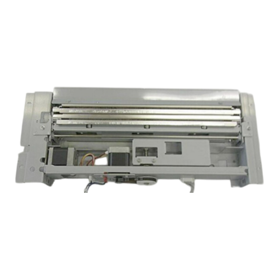
1. Replacement and Adjustment 7. Keep the decurl unit in the “Maintenance Position” as described below. Maintenance Position Lay the decurler unit [A] on temporary supports [C] as shown below. The entrance guide of the decurl unit must not touch the floor or any object. Otherwise, the sheets on the entrance gate may be bent or folded. -
Page 11: Sp Settings After Installing A New Decurler Unit
Decurl Unit and Electrical Components Side View SP Settings After Installing a New Decurler Unit 1. Turn on the main machine and then enter the SP mode. 2. Refer to the accessory sheet and enter the settings for SP1927-001 and SP1928-001. 3. -
Page 12: Decurl Unit Motor
1. Replacement and Adjustment [B]: Decurl Unit 3. DDRB [A] ( Decurl Unit Motor 1. Decurl unit (page 5 "Decurl Unit") 2. Remove the timing belt [A] and then remove the motor bracket [B] ( X2). -
Page 13: Decurl Feed Motor
Decurl Unit and Electrical Components 3. Separate the bracket [A] and decurl unit motor [B] ( x1). Decurl Feed Motor 1. Decurl unit (page 5 "Decurl Unit") 2. On the rear side, disconnect the motor ( x1). 3. At the rear side of the unit [A], disconnect the motor ( x2). -
Page 14: Decurl Unit Hp And Limit Sensor
1. Replacement and Adjustment 5. Remove the motor. Decurl Unit HP and Limit Sensor 1. Decurl unit (page 5 "Decurl Unit") 2. On the front side, remove the rack of the front pinion gear ( x1). - Page 15 Decurl Unit and Electrical Components 3. On the rear side, remove the rack of the rear pinion gear ( x1). 4. In the center, disconnect the tongue bracket ( x2). 5. Remove the decurl unit assembly [A] so that you can see both sensors [B]. •...
-
Page 16: Re-Installation
1. Replacement and Adjustment 6. Disconnect a sensor ( x1). 7. On the other side [C] (shown above) of the unit, release the sensor ( x3). Re-installation 1. Set the decurl unit assembly in the frame. 2. Fasten the tongue bracket before you attach the front and rear racks ( x2).
Need help?
Do you have a question about the DU5040 and is the answer not in the manual?
Questions and answers