Table of Contents
Advertisement
Quick Links
PRONAR SP. Z O.O.
17-210 NAREW, UL. MICKIEWICZA 101A, WOJ. PODLASKIE
TEL.:
+48 085 681 63 29
+48 085 681 63 81
FAX:
+48 085 681 63 83
OPERATOR`S MANUAL
MANURE SPREADER
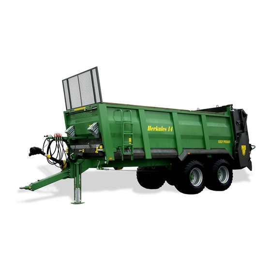
PRONAR N262/2
TRANSLATION OF THE ORIGINAL COPY OF THE MANUAL
EDITION NO. 624.01.UM.2B.EN
ISSUE 2B
08-2020
+48 085 681 64 29
+48 085 681 63 82
+48 085 682 71 10
www.pronar.pl
EN
Advertisement
Table of Contents

Subscribe to Our Youtube Channel
Related Manuals for PRONAR N262/2


Summary of Contents for PRONAR N262/2
- Page 1 PRONAR SP. Z O.O. 17-210 NAREW, UL. MICKIEWICZA 101A, WOJ. PODLASKIE TEL.: +48 085 681 63 29 +48 085 681 64 29 +48 085 681 63 81 +48 085 681 63 82 FAX: +48 085 681 63 83 +48 085 682 71 10 www.pronar.pl...
- Page 3 INTRODUCTION...
-
Page 4: Introduction
The manual instruction is intended for the end user. For this reason, some required maintenance is listed in the inspection tables but the procedure is not described in this publication. To perform them, call the manufacturer's authorized service center. U.10.1.EN PRONAR N262/2... -
Page 5: Introduction
ADVICE Additional instructions contained in the ADVICE manual describe useful information on op- erating the machine and are marked with a frame with the word ADVICE. U.02.1.EN PRONAR N262/2... -
Page 6: Designation Of Directions In The Manual
(operator facing the mechanism). direction. Turn left – turn the mechanism counter- Right side – the right hand side of the ob- clockwise (operator facing the mechanism). server facing the machine in the forward direction. U.03.1.EN PRONAR N262/2... -
Page 7: Checking The Machine After Delivery
• Check the condition of the paint flexible hydraulic and pneumatic coating. hoses. • Visually inspect machine compo- • Make sure there are no hydraulic oil nents for mechanical damage re- leaks. sulting, e.g., from incorrect machine • Check the manure lighting lamps. U.31.1.EN PRONAR N262/2... -
Page 8: Start-Up
(if present), adapter wheels). drive. • Make sure that the articulated tel- • Stop the tractor and turn off the escopic shaft (WPT) can be con- engine, immobilize the tractor and nected to the tractor (the shaft should PRONAR N262/2... - Page 9 Introduction the manure spreader with the parking brake. U.33.1.EN PRONAR N262/2...
- Page 10 Introduction PRONAR N262/2...
-
Page 13: Table Of Contents
Table of contents INTRODUCTION Introduction _________________________________________________________ 2 Symbols used in the manual ____________________________________________ 3 Designation of directions in the manual ____________________________________ 4 Checking the machine after delivery ______________________________________ 5 Start-up ___________________________________________________________ 6 GENERAL Identification ________________________________________________ 1.2 Intended use ________________________________________________ 1.4 Equipment __________________________________________________ 1.7 Terms of warranty ____________________________________________ 1.8 Transport ___________________________________________________ 1.9... - Page 14 Operation of the broken hydraulic support __________________________ 4.9 Test run ____________________________________________________ 4.11 Loading the loading box ________________________________________ 4.13 Disconnecting from the tractor ___________________________________ 4.15 Load transportation ___________________________________________ 4.16 Spreading and fertilizing dose adjusting ___________________________ 4.18 4.10 Clogging of the spreading mechanism _____________________________ 4.21 4.11 Use of tires __________________________________________________ 4.22 4.12...
-
Page 15: General
GENERAL... -
Page 16: Identification
After purchasing the machine, fields placed on the plates is presented in we recommend that you enter the indi- the table (1.1). vidual serial numbers of the axes in the When purchasing the machine, check that fields below. PRONAR N262/2... - Page 17 Contact with the service department requires provid- ing the factory number of the manure spreader and often the number of axle, so we recommend that you write these numbers in the manual and have access to them. E.3.10.624.01.1.EN PRONAR N262/2...
-
Page 18: Intended Use
Chapter 1 General 1.2 INTENDED USE Pronar manure spreader is designed for DANGER even spreading of all types of manure, peat The machine may not be used for purposes other and compost. Using the manure spreader than those for which it is intended. - Page 19 1 000 Clockwise (looking at the shaft PTO rotation direction head) – a different oil may be used, provided it can be mixed with oil in the manure spreader. Detailed information can be found in the product information card. PRONAR N262/2...
- Page 20 • overloading the manure spreader manure spreader elements, over the maximum load capacity. • for transporting and spreading toxic E.3.10.624.02.1.EN PRONAR N262/2...
-
Page 21: Equipment
ADDITIONAL AND OPTIONAL (wide angle shaft) EQUIPMENT shaft end on the tractor side, 6-splines • rear flaps shaft end on the tractor side, 21-splines • K80 ball link shaft end on the tractor side, 20-splines • rear beam E.3.10.624.03.1.EN PRONAR N262/2... -
Page 22: Terms Of Warranty
Chapter 1 General 1.4 TERMS OF WARRANTY PRONAR Sp. z o.o. in Narew guarantees DANGER smooth operation of the machine when it During road transport, the machine must be mount- is used in accordance with the technical ed on the platform of the vehicle in accordance with and operational conditions described in safety requirements and regulations. -
Page 23: Transport
The spreader tural elements of the spreader (stringers, must be correctly connected to the tractor crossbars). Transport handles are welded 624-E.03-1 Figure 1.3 Arrangement of transport handles spreader (1) carrying handle (2) bottom frame side member PRONAR N262/2... - Page 24 While driving, adjust the speed to the pre- attached spreader will not change its po- vailing road conditions, but it must not be sition relative to the transporting vehicle. greater than the maximum design speed. The fastening means must be selected E.3.10.624.05.1.EN 1.10 PRONAR N262/2...
-
Page 25: Threat To The Environment
It is pro- hibited to throw or pour oil into the sewage system or an oil waste disposal point. The container water reservoirs. should be kept away from heat sources, E.3.6.621.06.1.EN PRONAR N262/2 1.11... -
Page 26: Withdrawal From Use
(e.g. by dealing with the utilization of this type of means of the air tank drain valve). waste. In the event of parts being replaced, worn E.3.10.624.07.1.EN 1.12 PRONAR N262/2... -
Page 27: Safety Of Use
SAFETY OF USE... -
Page 28: Basic Safety Rules
• Before each start-up of the manure spreader using mudguards wheels. spreader, check that it is properly prepared for work, first of all in terms • Careless and improper use and PRONAR N262/2... - Page 29 • When operating the machine, use and properly fastened. protective gloves and appropriate • Pronar sp.z o.o. warns of the ex- tools. istence of a residual risk, therefore • Loading work should be carried out the application of the principles of...
-
Page 30: Safety When The Machine Aggregating
• Hitching and unhitching the spreader with the spreader's hydraulic oil. may only take place when the ma- • Before coupling the manure spreader, chine is immobilized by means of the make sure that both machines are parking brake. F.3.10.624.02.1.EN PRONAR N262/2... -
Page 31: Safety Rules For Operating Hydraulic And Pneumatic Systems
• Rubber hydraulic conduits must be replaced every 4 years regardless of • In the event of injuries being caused by pressurized hydraulic oil, contact their technical condition. a doctor immediately. Hydraulic oil F.3.10.624.03.1.EN PRONAR N262/2... -
Page 32: Safe Operation Of The Pto Shaft
Contact it may cause an accident. A damaged shaft must be repaired or replaced. with rotating PTO shaft may cause serious injury. • Disconnect the shaft drive each PRONAR N262/2... - Page 33 • It is forbidden to use safety chains to spect to each other. support the shaft during standstill or • Secure the shaft guard against transporting the manure spreader. F.3.10.624.04.1.EN PRONAR N262/2...
-
Page 34: Rules Of Safe Technical Service
• Before starting repair work on hy- access by unauthorized persons. draulic or pneumatic systems, the • During maintenance repair residual oil or air pressure must be work, the manure spreader may be PRONAR N262/2... - Page 35 • It is forbidden to carry out independent foam extinguisher. repairs of elements of the hydraulic or • In the event of work requiring the pneumatic system, i.e. control valves, spreader to be raised, use properly modules, actuators and regulators. In PRONAR N262/2...
- Page 36 • It is forbidden to install additional (welding, surfacing, straightening, devices or accessories that do not etc.) is prohibited and requires re- comply with the specification spec- placement of parts with new ones. ified by the Manufacturer. F.3.10.624.05.1.EN 2.10 PRONAR N262/2...
-
Page 37: Safe Driving Rules
PRONAR N262/2 2.11... - Page 38 • The arrangement of the load must the tractor operator at all times. not cause overloading of the running • Use extreme caution when passing gear, as well as the hitch spreader near overhead power lines. F.3.10.624.06.1.EN 2.12 PRONAR N262/2...
-
Page 39: Tires
• Check the correct tightening of the • Tire valves should be protected with wheel nuts according to the assumed suitable caps to avoid penetration of schedule. dirt. • Avoid damaged surfaces, sudden F.3.10.624.07.1.EN PRONAR N262/2 2.13... -
Page 40: Description Of Residual Risk
Chapter 2 Safety of use 2.8 DESCRIPTION OF RESIDUAL RISK Pronar Sp. z o. o. in Narew made every • presence of persons or obstacles in effort to eliminate the risk of an accident. areas invisible from the operator's However, there is some residual risk that position. -
Page 41: Information And Warning Stickers
Do not take up space under the raised tailgate of the adapter. Caution. Do not step on the chain conveyor if the engine is running and 70N-00000008 the PTO shaft is engaged. Caution. Danger of crushing. 70N-00000009 Keep a safe distance from rotating spreading discs. PRONAR N262/2 2.15... - Page 42 Permissible load on the coupling device. 544N-00000003 High pressure fluid - body injection. 535N-00000009 The air pressure in the wheels depends on the used tires The air pressure in the wheels depends on the used tires (1) - F.3.10.624.09.1.EN 2.16 PRONAR N262/2...
- Page 43 Safety of use Chapter 2 N262/2 PRONAR Herkules 18 n=1000 min.18 mm max.25 mm 40 kN min. 40 m Łączenie tylko z zaczepem do przyczep jednoosiowych 624-F.02-1 Figure 2.3 Arrangement of information and warning stickers PRONAR N262/2 2.17...
- Page 44 Chapter 2 Safety of use 2.18 PRONAR N262/2...
-
Page 45: Construction And Principle Of Operation
CONSTRUCTION AND PRINCIPLE OF OPERATION... -
Page 46: Technical Characteristics
-Parameter: Permissible total weight - depending on legal restrictions on the target market, may differ from the given. Information on tires is provided in Chapter 7 'Tire assembly’ G.3.10.624.01.3.EN PRONAR N262/2... -
Page 47: General Construction
These are single wheels equipped with calliper brakes actuated by suspension consists of two driving axles in a tandem arrangement on parabolic mechanical cam expanders. A ladder (12) is mounted on the left side springs connected by a swing arm. The PRONAR N262/2... - Page 48 At the customer's request, the manure The main working element is the shredding spreader can be equipped with a rear adapter (7) with two impellers arranged beam (19). G.3.10.624.02.1.EN PRONAR N262/2...
-
Page 49: Feeding Mechanism
(4) mounted to the reduction gear (3). mechanism (6) and on the front wheels of the tensioning assembly (5). Four G.3.10.624.03.1.EN PRONAR N262/2... -
Page 50: Powertrain
PTO shaft to the manure spreader mech- mission when the torque exceeds the cali- anisms through the articulated shafts (1), bration value of the clutch. After reducing (2), (3), (4), (5) to the reduction gear of the the speed or stopping the power take-off, PRONAR N262/2... - Page 51 1 000 rpm. The use of a different PTO speed will cause the spreading drums to have insufficient ro- tation, or the drive will be exposed to dam- age. G.3.10.624.04.1.EN PRONAR N262/2...
-
Page 52: 2-Roller Spreading Adapter
(4) on which drums. The frame is made up of the vertical spreading drums (5) are mounted left side wall (1) and right side wall (2) PRONAR N262/2... - Page 53 Used knives should be replaced. Working tools are replaceable crushing The adapter is driven by the tractor drive knives (6) twisted to the spreading shafts. and PTO shaft at a speed of 1 000 rpm. G.3.10.624.05.1.EN PRONAR N262/2...
-
Page 54: Rear Flaps Of The Adapter
The selection of the spreading limitation side is done by means of the hydraulic walls of the adapter with hinges. The flaps are opened sideways using hydraulic valves (4). When using dampers as de- flectors, i.e. blocking the damper on one cylinders. 3.10 PRONAR N262/2... - Page 55 Closing is accomplished The hydraulic hoses for controlling the by changing the spreader setting on the adapter flaps around the connection plugs tractor. have been marked with the information G.3.10.624.06.1.EN PRONAR N262/2 3.11...
-
Page 56: Hydraulic System Of The Feeding Mechanism
(3) located at the hydraulic motor. arrows indicating the direction of hydraulic oil flow have been placed on the cables At the moment of reloading, when the conveyor is overloaded or mechanically in the vicinity of the connection plugs to 3.12 PRONAR N262/2... - Page 57 (3.6). CAUTION ADVICE The hydraulic system of the covers was It is forbidden to remove seals and change filled with L-HL32 Lotos hydraulic oil. factory settings on the overload valve and flow regulator. G.3.10.624.07.1.EN PRONAR N262/2 3.13...
-
Page 58: Hydraulic Valve System
The manure spreader is equipped with adapter in the side guides and ensures a loading box slide (1) as standard. It safe transport of transported materials is mounted in front of the spreading (e.g. compost, peat) on public roads, and 3.14 PRONAR N262/2... - Page 59 The hydraulic cylinders ADVICE opening and closing the slide are con- The hydraulic system of the covers was trolled by means of a distributor in the filled with L-HL32 Lotos hydraulic oil. G.3.10.624.08.1.EN PRONAR N262/2 3.15...
-
Page 60: Hydraulic System Of The Broken Support
Disassembly and along the valve. Hydraulic oil fed from the assembly is performed by ejecting or in- tractor's hydraulic distributor extends the serting a single-acting hydraulic piston cylinder piston to the desired height. The rod. 3.16 PRONAR N262/2... - Page 61 The shut-off switch a quick coupler - plug (5) and secured with must be in the closed position. a stopper (6). G.3.10.624.09.1.EN PRONAR N262/2 3.17...
-
Page 62: Hydraulic Steering Lock System
The axle steering lock is made possible tending or retracting the hydraulic cylinder by the 2-pipe hydraulic system shown in piston rod (1). The hydraulic hoses (2) for figure (3.9). connecting to the tractor are equipped with 3.18 PRONAR N262/2... - Page 63 Construction and principle of operation Chapter 3 quick couplings - plugs (3) and secured with plugs (4). G.3.10.624.10.1.EN PRONAR N262/2 3.19...
-
Page 64: Hydraulic System (Control From The Spreader)
It consists of four tractor's external hydraulic system. The independent circuits controlling individual control is carried out by means of levers 3, machine components: 4, 5, 6 - figure (3.10). G.3.10.624.11.1.EN 3.20 PRONAR N262/2... -
Page 65: Service Brake
List of symbols used in the schemes Symbol Description Pneumatic connection, plug Pneumatic connection, socket Drainage valve Main control valve Relay valve Automatic braking force regulator Manual braking force regulator Wire connection Air tank Brake cylinder Control valve (connector) Air filter PRONAR N262/2 3.21... - Page 66 Switching to the appropriate oper- spreader is disconnected from the tractor. ating mode is done manually by the ma- After connecting the air line to the tractor, chine operator before starting the journey 3.22 PRONAR N262/2...
- Page 67 In the case of pneumatic cylinders, the air • B - „Half-load” supplied to the cylinder exerts pressure on • C - „Full load”. the diaphragm, which in turn moves the Pneumatic brake cylinders used in the cylinder piston rod and rotates the axle PRONAR N262/2 3.23...
- Page 68 Automatic braking force regulator (3) - by the extraction springs. The relay valve figure (3.12) adjusts braking pressure (10) is designed to increase the aeration depending on how much the manure 3.24 PRONAR N262/2...
- Page 69 DIN ISO 1728, which makes it impossible (2) connection body to mistakenly connect the connectors to agricultural tractor sockets. After uncou- prepared for this purpose, located on the pling the manure spreader, pneumatic pipe support. connections should be placed in sockets G.3.10.624.11.1.EN PRONAR N262/2 3.25...
-
Page 70: Parking Brake
The parking brake must be released before By turning the mechanism crank (1) driving - the steel cable must hang loosely. (clockwise), the steel cable tensions, 624-G.16-1 Figure 3.17 Parking brake construction (1) crank mechanism (2) spreader lever (3) steel cable G.3.1.624.12.1.EN 3.26 PRONAR N262/2... -
Page 71: Hydraulic Lock System
Raising or lowering the drawbar is used to the tractor. 624-G.19-1 Figure 3.18 Construction of drawbar with hydraulic shock absorption (1) drawbar (2) lower frame (3) hydraulic cylinder (4) hydraulic accumulator (5) quick coupler - plug (6) hydraulic lock G.3.1.624.13.1.EN PRONAR N262/2 3.27... -
Page 72: Electrical Lighting Installation
Arrangement of electric installation elements and reflective elements (1) front position lamp (2) white reflector (3) connection socket (4) orange reflector (5) rear multifunctional lamp (6) connection cable 7pin-7pin (7) distinctive plate (8) license plate lamp (9) warning plate G.3.1.624.14.1.EN 3.28 PRONAR N262/2... - Page 73 Multifunctional rear right lamp Orange Multifunctional rear left lamp Green Board lighting lamp Brown Yellow CAUTION The machine lamps work only when the manure spreader is connected to the agricultural tractor and the position lights are on. PRONAR N262/2 3.29...
- Page 74 2/54 Not used 3/31 Weight (white) Right indicator (green) Rear right position light 3/31 5/58R (brown) 5/58R 6/54 STOP light (red) Rear left position light (black) 624-G.20-1 Figure 3.21 Connection socket (1) socket (2) beam side view 3.30 PRONAR N262/2...
-
Page 75: Rules Of Use
RULES OF USE... -
Page 76: Adjusting The Position Of The Drawbar
- figure (4.1): • remove the coupling of the drawbar • immobilize manure spreader with with the lower frame (7) by un- parking brake. screwing the screws (8) and pulling PRONAR N262/2... - Page 77 • after determining the height of the maximum (drawbar eye in the maximum upper position), drawbar cushioning will drawbar, mount the pins (3) and tighten the screws (8) to the torque not work. according to table 5.8. H.3.10.624.01.1.EN PRONAR N262/2...
-
Page 78: Connecting And Coupling Of The Manure
Pay attention • Immobilize manure spreader with to the compatibility of oils in the tractor's hydraulic parking brake. system and in the hydraulic systems of the manure spreader. Turn brake mechanism PRONAR N262/2... - Page 79 (4.1) or tractor hitch. shoes. In this case, after starting the tractor and the air compressor, wait until the air in the pneumatic • Turn off the tractor engine and tank is topped up. remove the keys from the ignition. PRONAR N262/2...
- Page 80 • Connect the main connection cable for the lighting installation - see chapter (3.15). • Perform daily inspection of the manure spreader. • If the manure spreader is functional, you can start working. • Immediately before driving, remove PRONAR N262/2...
-
Page 81: Telescopic Support Service
• Install the safety pin. more slowly and you do not need to apply • Set the crank to neutral (A). much force to raise the machine's drawbar. Lowering the support Raising the support • Remove the securing bolt. PRONAR N262/2... - Page 82 (if the • Set the crank (3) to position (B) or manure spreader is to be connected (C). to the tractor). • By turning the crank in the right H.3.10.624.03.1.EN PRONAR N262/2...
-
Page 83: Operation Of The Broken Hydraulic Support
• By operating the distributor in the The manure spreader must NOT be driven if the sup- tractor, raise the support foot. port securing elements - bolt (3) and cotter pin (4) are damaged or lost. • Lock the support position by moving PRONAR N262/2... - Page 84 • Release the cotter pin (4) and pull the • Lock the support position by moving safety pin out of position (B) - figure the valve lever (5) to the closed (4.4). position. • Turn support to position (1). H.3.10.624.04.1.EN 4.10 PRONAR N262/2...
-
Page 85: Test Run
"0" to the maximum • At low revolutions start the PTO drive "10" position. Use the appro- in the tractor (starting the drive of the priate tractor manifold lever to spreading drums of the adapter). PRONAR N262/2 4.11... - Page 86 If the fault cannot be rectified or remedied, rubbing moving parts against the it may invalidate the warranty, contact the spreader structure, point of sale or the Manufacturer directly • hydraulic oil leakage, to clarify the problem or repair it. H.3.10.624.05.1.EN 4.12 PRONAR N262/2...
-
Page 87: Loading The Loading Box
Approximate volumetric weights of selected loads Type of material Volumetric weight kg/m Organic fertilizers: Old manure 700 - 800 Settled down manure 800 - 900 Fresh manure 700 - 750 Compost 950 – 1,100 Fresh peat 700 - 850 PRONAR N262/2 4.13... - Page 88 (4.1). Therefore, cause contamination of the road. If this is pay special attention not to overload the not possible, it is prohibited to transport manure spreader. this type of load H.3.10.624.06.1.EN 4.14 PRONAR N262/2...
-
Page 89: Disconnecting From The Tractor
• Disconnect hydraulic system lines and drive the tractor away. and put in appropriate sockets. H.3.10.624.07.1.EN Protect plugs of these wires against contamination by putting on caps. • Disconnect the pneumatic system lines. • Secure the cable ends with covers. PRONAR N262/2 4.15... -
Page 90: Load Transportation
• While driving, obey the rules of the for the tractor and spreader operator, or other road users. road, signal the change of direction 4.16 PRONAR N262/2... - Page 91 • When driving, avoid sharp turns, es- 8°. Moving the manure spreader over steep slopes may cause overturning pecially on slopes. • When traveling on public roads, the due to loss of stability. H.3.10.624.08.1.EN PRONAR N262/2 4.17...
-
Page 92: Spreading And Fertilizing Dose Adjusting
624-H.05-1 (3). Figure 4.5 Feed speed adjustment (1) flow regulator (2) valve support • The feed speed is reduced by turning (3) adjustment knob the regulator knob clockwise to the 4.18 PRONAR N262/2... - Page 93 • Activate the adapter by engaging the of the hydraulic connections and protective PTO drive on the tractor. covers on the manure spreader and the Start the tractor PTO shaft articulated telescopic shaft again. at slow revolutions to avoid PRONAR N262/2 4.19...
- Page 94 PTO shaft after first switching off the ADVICE chain conveyor drive. This protects If the wide-angle shaft is mounted to connect the manure spreader with the tractor, it is not necessary to disengage the PTO drive at the headland during work. H.3.10.624.09.1.EN 4.20 PRONAR N262/2...
-
Page 95: Clogging Of The Spreading Mechanism
• Start the tractor and engage the PTO unauthorized persons. drive in order to clean the remaining • Remove the elements blocking the material. spreading adapter with a suitable H.3.10.624.10.1.EN PRONAR N262/2 4.21... -
Page 96: Use Of Tires
Wheel nuts should be tightened in accordance with the the tires. • Avoid damaged surfaces, sudden recommendations contained in the Technical Maintenance Schedule and variable maneuvers, and high speeds when turning. chapter. • Regularly check and maintain proper H.3.10.624.11.1.EN 4.22 PRONAR N262/2... -
Page 97: Cleaning
• Do not use organic solvents, prepa- The water temperature should rations of unknown origin or other not exceed 55 substances that may damage the Paint damage occur lacquered, rubber or plastic surface. PRONAR N262/2 4.23... - Page 98 After washing, wait for the manure spreader to dry and then grease all grease points as recommended. Wipe off excess grease or oil with a dry cloth. During work, use appropriate, close-fitting protective clothing, gloves and the right tools. H.3.10.624.12.1.EN 4.24 PRONAR N262/2...
-
Page 99: Preparation For The End Of The Season
• tires should be maintained at least • check tire pressure on road wheels, once a year using the available • a corroded or damaged surface means for this purpose. should be cleaned and properly H.3.10.624.13.1.EN PRONAR N262/2 4.25... -
Page 100: Preparation For The Season
• Check technical condition of PTO scratches and cracks. shaft, guards and securing chains. • Check the condition of the slats of the • Check the oil level in the adapter floor conveyor mechanism, replace if necessary. gear. H.3.10.624.14.1.EN 4.26 PRONAR N262/2... -
Page 101: Storage
• For long-term storage outside the room, it must be protected against • Store the articulated telescopic shaft to connect with the tractor in a hori- the effects of weather conditions, es- pecially factors causing corrosion of zontal position. H.3.10.624.15.1.EN PRONAR N262/2 4.27... - Page 102 Chapter 4 Rules of use 4.28 PRONAR N262/2...
-
Page 103: Technical Inspection Schedule
TECHNICAL INSPECTION SCHEDULE... -
Page 104: General
Repair of the machine during the war- loses the warranty. ranty period may only be carried out by The manure spreader's warranty in- Authorized Sales and Service Points spection is only carried out by authorized (APSiO). In the event of unauthorized service centres. I.3.10.624.01.1.EN PRONAR N262/2... -
Page 105: Periodic Inspections Of The Manure Spreader
Each time before carrying out this inspec- Maintenance Operator tion, perform a daily inspection, inspection every 1 month of manure spreader use and inspection every 3 months. Inspection carried out every 4 years of manure Maintenance Service spreader use (1) - post-warranty service PRONAR N262/2... - Page 106 Cleaning the drainage valve 5.23 Checking of parking brake cable tension • 5.24 Hydraulic system Checking • 5.26 • Control of pneumatic braking system 5.27 See table: Suspension control Suspension control 5.28 schedule. See table: Spreader lubrication Lubrication 5.30 schedule. PRONAR N262/2...
- Page 107 Piston rod stroke in hydraulic systems 25 - 45 mm Minimum brake lining thickness 5 mm With the brake de- Angle between the spreader axis and the fork pressed Parking brake Permitted parking brake cable clearance 20 mm I.3.10.624.02.1.EN PRONAR N262/2...
-
Page 108: Preparation Of The Manure Spreader For Inspection
• In exceptional cases, release the that the machine will not roll during manure spreader parking brake, e.g. inspection. when measuring the play of the axle • In case when the wheel needs to be shaft bearings. Take special care. I.3.10.624.03.1.EN PRONAR N262/2... -
Page 109: Checking The Air Pressure In The Wheels
(1) information sticker (2) valve the tire as a result of delamination of the material. Incorrect tire pressure also causes faster tire wear. ADVICE The tire pressure value is on the information sticker on the wheel rim - figure (5.2). I.3.10.624.04.1.EN PRONAR N262/2... -
Page 110: Air Tank Drainage
• If the valve stem does not want to return to its position, wait until the tank 624-I.03-1 empties. Then unscrew and clean or Figure 5.3 Air tank (1) drain valve (2) air tank replace the valve with a new one. I.3.10.624.01.EN PRONAR N262/2... -
Page 111: Checking Plugs And Connection Sockets
(e.g. silicone lubricants for rubber degree of cleanliness of connections elements). and sockets on the agricultural tractor. Each time before connecting the ma- If necessary clean or repair tractor sockets. chine, check the technical condition and I.3.10.624.06.1.EN PRONAR N262/2... -
Page 112: Covers Inspection
• Check the condition of guards and safety chains of PTO shafts. THE SCOPE OF ACTIVITIES • If necessary, tighten the screw con- • Check that the covers are correctly nections of the covers. I.3.10.624.07.1.EN 5.10 PRONAR N262/2... -
Page 113: Transmission Oil Filling And Top-Up
• If necessary, unscrew the plug (5) and up the sight glass. add oil to the required level. Tighten • Check the oil level in the chain con- the plug. veyor drive gear (2) through the The oil level should be halfway PRONAR N262/2 5.11... - Page 114 Chapter 5 Technical inspection schedule transparent oil sight glass (4). the plug. • If necessary, unscrew the plug (6) and The oil level should be halfway add oil to the required level. Tighten up the sight glass. I.3.10.624.08.1.EN 5.12 PRONAR N262/2...
-
Page 115: Control And Regulation Of Floor Conveyor Chains Tension
The tension is measured on the springs of the front (1) and the conveyor front cover (3) is 18 - 25 mm - figure (5.6). winding mechanism, at the front of the I.3.10.624.09.1.EN PRONAR N262/2 5.13... -
Page 116: Checking And Replacing The Adapter Knives
Table 5.4. List of replaceable elements Marking Name, catalogue number Quantity Figure 5.7 Flat knife / 535N-17010001 Bent knife / 535N-17010002 Bent knife II/ 535N-17020001 Screw M16x1,5x40-8.8 PN-EN ISO 8676 Self-locking nut M16x1,5-8 A2J PN-EN ISO 10512 5.14 PRONAR N262/2... - Page 117 Technical inspection schedule Chapter 5 clamping screws should be replaced. The Blades fixing bolts should be mounted list of replaceable elements is presented with their heads up. Tighten the nuts with in the table (5.4). 170 Nm. I.3.10.624.10.1.EN PRONAR N262/2 5.15...
-
Page 118: Checking The Manure Spreader Before Driving Off
Driving with defective lighting installations braking is prohibited. If the manure spreader is damaged, it should be dis- continued until it is repaired. 526-I.05-1 Figure 5.8 Brake cylinder other systems while operating the the actuator (6) are not clogged with manure spreader. I.3.10.624.11.1.EN 5.16 PRONAR N262/2... -
Page 119: Measurement Of Air Pressure, Check Tires And Wheels
• Inspect the tire for defects, cuts, pecially around welds and in the place deformations, bumps indicating me- contact with the tire. chanical damage to the tire. In the I.3.10.624.12.1.EN PRONAR N262/2 5.17... -
Page 120: Cleaning The Air Filters
• Slide out the filter securing lock (1). cated in the filter housing. Installation • Hold the filter cover (2). should be in reverse order. I.3.10.624.13.1.EN 5.18 PRONAR N262/2... -
Page 121: Checking Brake Lining Wear
• The brake shoes should be replaced • Remove the upper and lower plugs if the thickness of the brake lining is and then check the thickness of the less than 5 mm. lining. • Check the remaining linings for wear. I.3.10.624.14.1.EN PRONAR N262/2 5.19... -
Page 122: Checking The Clearance Of The Axle Bearings
When checking bearings, make sure excessive resistance and jamming - that any noticeable looseness comes figure (5.12). from the bearings, not the suspension • Turn the wheel so that it rotates very system (e.g. looseness on the spring 5.20 PRONAR N262/2... - Page 123 Dimensions if necessary. penetration of dirt and moisture into the hub, which will result in much faster wear of bearings and hub seals. Bearing life depends on spreader operating condi- tions, load, vehicle speed and lubrication conditions. I.3.10.624.11.EN PRONAR N262/2 5.21...
-
Page 124: Checking Of Mechanical Brakes
• Measure the distance Y with the given in table 5.3, the brake should tractor brake pedal pressed. be adjusted. • Calculate the distance difference X-Y I.3.10.624.16.1.EN 5.22 PRONAR N262/2... -
Page 125: Cleaning The Drainage Valve
• Clean the valve, blow with com- Figure 5.14 Air tank (1) drain valve (2) tank pressed air. • Replace the copper gasket. air, check the tank for leaks. • Screw in the valve, fill the tank with I.3.10.624.17.1.EN PRONAR N262/2 5.23... -
Page 126: Checking Of Parking Brake Cable Tension
• Turn the parking brake crank (2) to- (2) as far as possible by turning the wards (B) and apply the parking crank in the direction (A). brake. • Loosen the nuts (4) of the bow clamps • Check cable tension (1). 5.24 PRONAR N262/2... - Page 127 • Apply the parking brake and release If it is necessary to change the brake cable, it again. Check (approximately) cable refer to chapter 6.2 „Replacing the parking slack. When the service and parking brake cable”. brakes are completely released, the I.3.10.624.18.1.EN PRONAR N262/2 5.25...
-
Page 128: Hydraulic System Checking
(scratch the surface of cylinders, etc.) When the cylinder is fully extended, check the seal locations. Slight leaks are I.3.10.624.19.1.EN 5.26 PRONAR N262/2... -
Page 129: Control Of Pneumatic Braking System
In the event of a leak, the compressed Repair, replacement or regeneration of pneumatic system components may only be carried out in a air will leak out in places of damage with specialized workshop. a characteristic hiss. The system leak I.3.10.624.20.1.EN PRONAR N262/2 5.27... -
Page 130: Suspension Control
- unscrew the lock nuts, ation. - tighten the nuts diagonally to the specified torque After 5000 km or after - screw on the lock nuts and tighten diagonally to the 1500 hours of work, then specified torque. once a year. 5.28 PRONAR N262/2... - Page 131 CAUTION ADVICE In the event of severe conditions of use or heavy The manure spreader screw connections should be tightened under load. use, maintenance should be carried out more often. I.3.10.624.21.1.EN PRONAR N262/2 5.29...
-
Page 132: Lubrication
Lubricate the spring surface and Table 5.6. Lubricants Item Symbol Description general purpose machine grease (lithium, calcium), solid grease for heavily loaded components with the addition of MOS graphite anti-corrosive spray plain machine oil, silicone spray grease 5.30 PRONAR N262/2... - Page 133 D - working day (8 hours of manure spreader oper- manufacturer's instructions. ation), M-month Table 5.7. Spreader lubrication schedule Name Hub bearings (1) (2 in each hub) 526-I.19-1 Rigid axle expander shaft bushings (1) Rigid axle expander arm (2) 624-I.10-1 PRONAR N262/2 5.31...
- Page 134 Technical inspection schedule Name Spring leaves (1) Spring sliding surface (2) Spring pin (3) 624-I.11-1 Control arm pin (4) Draw bar hitching eye (1) Rotating cable (2) 624-I.12-1 Spring fixing pin (1) Draw bar bolt (2) 624-I.13-1 5.32 PRONAR N262/2...
- Page 135 Technical inspection schedule Chapter 5 Name Wheel axle guiding the brake cable 624-I.21-1 Parking brake mechanism 624-I.22-1 Front axle sprocket bear- ings 624-I.14-1 Chain conveyor drive shaft bearings 624-I.15-1 PRONAR N262/2 5.33...
- Page 136 Chapter 5 Technical inspection schedule Name Surface of the spline of the shaft 624-I.16-1 Rear cover cylinder ears 624-I.17-1 Tailgate hinges 624-I.19-1 Telescopic support with gear 624-I.20-1 5.34 PRONAR N262/2...
- Page 137 (1) Steering axle expander arm The steering spindle axis 624-I.23-1 Ladder rotation pin 624-I.29-1 PTO shaft * 624-I.24-1 * - For detailed information on operation and maintenance, refer to the operating instructions supplied with the shaft. I.3.10.624.22.1.EN PRONAR N262/2 5.35...
-
Page 138: Screw Connections Inspection
(5.18). Wheel nuts must not be tightened with 589-I.10-1 impact wrenches, due to the danger of Figure 5.17 Metric thread screw (1) strength class, (d) thread diameter exceeding permissible tightening torque, which may result in breaking the 5.36 PRONAR N262/2... - Page 139 The tightening torque of M20x80 bolts should be 395Nm. Tighten the screws diagonally with a torque wrench. 395Nm 624-I.28-1 Figure 5.19 The draw bar eye tightening I.3.10.624.23.1.EN PRONAR N262/2 5.37...
-
Page 140: Transmission Oil Change
(3) located only in the middle gear, wait the side gears, so adding oil to the appropriate level until all the oil has drained from the side gears. should be done in stages, periodically checking the oil level until it stabilizes. 5.38 PRONAR N262/2... - Page 141 • Unscrew the filler cap and add oil to the tractor engine. the required level. • Loosen the cover screws (4). • Check the plug seal, replace if • Prepare the container and drain the necessary. I.3.10.624.24.1.EN PRONAR N262/2 5.39...
-
Page 142: Replacement Of Hydraulic Hoses
Chapter 5 Technical inspection schedule 5.25 REPLACEMENT OF HYDRAULIC HOSES Rubber hydraulic hoses should be re- placed every 4 years regardless of their technical condition. This operation should be entrusted to specialized workshops. I.3.1.526.20.1.EN 5.40 PRONAR N262/2... -
Page 143: Technical Support
TECHNICAL SUPPORT... -
Page 144: Wheel Assembly And Disassembly
• Lower the manure spreader, tighten of the lift base on the ground to the nuts according to the recom- prevent penetration into the ground. mended torque and the given order • Remove the wheel. - see chapter 5.23„Checking screw connections” J.3.10.624.01.1.EN PRONAR N262/2... -
Page 145: Parking Brake Cable Replacement
(2). the other end of the cable in a similar • Clean the parking brake components. manner. • Lubricate the parking brake crank • Adjust the cable tension - see chapter PRONAR N262/2... - Page 146 Secure the ends of the cable with a shrink tube. mechanism and loosen again. If The distance between the clamps should be 30 mm, with the first clamp placed as close as possible to necessary, correct the brake cable the thimble. tension. J.3.10.624.02.1.EN PRONAR N262/2...
-
Page 147: Adjusting The Clearance Of The Axle Bearings
(1). operating conditions. • Gently tap the hub with a rubber or • Secure the castellated nut with wooden hammer. J.3.10.624.03.1.EN PRONAR N262/2... -
Page 148: Brake Adjustment
(1) so range, and the angle between the piston that when fully braked the angle of oper- rod (1) and the expander arm (3) should ation is approx. 90 °. PRONAR N262/2... - Page 149 (45mm), the system should be adjusted. When removing the cylinder fork (6), re- member or mark the original position of the cylinder fork pin (7). The mounting position depends on the type of braking PRONAR N262/2...
- Page 150 (6.7) of the cylinder mark with a line • Remember or mark the original po- (A) the position of the maximum re- sition of the cylinder fork (6) in the ex- traction of the piston rod with the pander arm bore (3). PRONAR N262/2...
- Page 151 • Install the piston rod fork pin and of the brake linings and / or overheating of the brake. The diaphragm actuator should not be opened. The washers and secure the pin with membrane is pasted and may lose its seal. cotter pins. PRONAR N262/2...
- Page 152 • If any drum is too hot, correct the • If the piston rod stroke is not within brake adjustment and perform the the correct operating range, repeat test drive again. J.3.10.624.04.1.EN 6.10 PRONAR N262/2...
-
Page 153: Electrical System Service And Warning Elements
The light source in the lamps are LEDs and in case of damage are only replaced as a complete lamp lead. without the possibility of repair or regeneration. • Make sure the connection cable is J.3.10.624.05.1.EN PRONAR N262/2 6.11... -
Page 154: Adapter Disassembly And Assembly
624-J.03-1 Figure 6.8 Adapter disassembly and assembly (1) adapter, (2) adapter flaps (additional equipment), (3) transport hook for the adapter, (4) M16x40 screw, (5) M14x40 screw, (6) hydraulic conduit plug, (7) pin 6.12 PRONAR N262/2... - Page 155 (4) connecting the it against tipping over. adapter with the load box. • Installation should be made in re- • Unscrew the screws (5) that connect verse order. the adapter to the bottom side. J.3.10.624.08.1.EN PRONAR N262/2 6.13...
-
Page 156: Assembly And Disassembly Of Silo Extensions
624-J.04-1 Figure 6.9 Assembly and disassembly of silo extensions (1) front left extension, (2) rear left extension, (3) front right extension, (4) rear right extension, (5) post profile, (6) post support, (7) crossbar J.3.10.624.09.1.EN 6.14 PRONAR N262/2... -
Page 157: Consumables
ADVICE however long-term effects on the skin or eyes may cause irritation. In the event of Lubrication frequency (Table Spreader lubrica- tion schedule). contact of oil with skin, wash the place of PRONAR N262/2 6.15... - Page 158 Table 6.1. Characteristics of oil L-HL 32 Item Name Unit Viscosity classification according to ISO 3448VG Kinematic viscosity at 400C 28.8 – 35.2 Qualitative classification according to ISO 6743/99 Quality classification according to DIN 51502 Flash-point J.3.10.624.06.1.EN 6.16 PRONAR N262/2...
-
Page 159: Faults And How To Remove Them
Replace brake shoes. Check the oil quality, make sure that the oils in both machines are of the same Incorrect hydraulic Incorrect hydraulic oil vis- system operation. cosity. grade. If necessary, change the oil in the tractor and/or spreader. PRONAR N262/2 6.17... - Page 160 Roller too short or too long. tions in the manual provided by the shaft manufacturer. Incorrect selection of the Small spreading Change the PTO shaft speed on the trac- PTO shaft speed in the width. tor to 1000 rpm. tractor. J.3.10.624.07.1.EN 6.18 PRONAR N262/2...
-
Page 161: Tire Assembly
TIRE ASSEMBLY... - Page 162 400 kPa 600/55-26.5 16PR 170A8 20.00x26.5H2 ET=-50 260 kPa 600/55R26.5 165D 176A8 20.00x26.5H2 ET=-50 400 kPa 710/45-26,5 169A8 24.00x26.5; ET=-50 240 kPa 700/50-26.5 16PR 174A8 24.00x26.5H2; ET=-80 240 kPa 710/50R26,5 170D 181A8 24.00x26.5H2; ET=-80 400 kPa width over 2550 PRONAR N262/2...
Need help?
Do you have a question about the N262/2 and is the answer not in the manual?
Questions and answers