Table of Contents
Advertisement
Quick Links
INTRODUCTION
Information contained herein is current at date of publication. As a result of improvements,
some numerical values and illustrations contained in this publication may not correspond to the
factual specification of the machine supplied to the user. The manufacturer reserves the right to
introduce design changes in machines produced that facilitate operation and improve the quality
of their work, without making minor amendments to this Operator's Manual.
This Operator's Manual is an integral part of the machine's documentation. Before using the
machine, the user must carefully read
recommendations. This guarantees safe operation and ensures malfunction free work of the
machine. The machine is designed to meet obligatory standards, documents and legal
regulations currently in force.
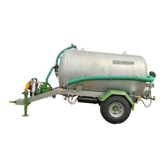
The manual describes the basic safety rules and operation of Pronar T314, Pronar T315 and
Pronar T316 slurry spreaders.
If the information contained in the Operator's Manual needs clarification then the user should
refer for assistance to the sale point where the machine was purchased or to the Manufacturer.
MANUFACTURER'S ADDRESS:
CONTACT TELEPHONES
PRONAR Sp. z o.o.
ul. Mickiewicza 101A
17-210 Narew
+48 085 681 63 29
+48 085 681 63 81
this
Operator's Manual and observe all
+48 085 681 64 29
+48 085 681 63 82
Advertisement
Table of Contents

Subscribe to Our Youtube Channel
Related Manuals for PRONAR T314


Summary of Contents for PRONAR T314
- Page 1 The machine is designed to meet obligatory standards, documents and legal regulations currently in force. The manual describes the basic safety rules and operation of Pronar T314, Pronar T315 and Pronar T316 slurry spreaders. If the information contained in the Operator's Manual needs clarification then the user should refer for assistance to the sale point where the machine was purchased or to the Manufacturer.
- Page 2 SYMBOLS APPEARING IN THIS OPERATOR'S MANUAL Information, descriptions of danger and precautions and also recommendations and prohibitions associated with user safety instructions are marked: and also preceded by the word "DANGER”. Failure to observe the instructions may endanger the machine operator's or other person's health or life. Particularly important information and instructions, the observance of which is essential, are distinguished in the text by the sign: and also preceded by the word "ATTENTION".
- Page 3 DIRECTIONS USED IN THIS OPERATOR'S MANUAL Left side – side to the left hand of the operator facing in the direction of machine's forward travel. Right side – side to the right hand of the operator facing in the direction of machine's forward travel.
-
Page 5: Table Of Contents
TABLE OF CONTENTS 1 BASIC INFORMATION IDENTIFICATION 1.1.1 IDENTIFICATION OF SLURRY TANKER 1.1.2 AXLE IDENTIFICATION 1.1.3 LIST OF SERIAL NUMBERS PROPER USE EQUIPMENT TERMS & CONDITIONS OF WARRANTY TRANSPORT 1.5.1 TRANSPORT ON VEHICLE 1.5.2 INDEPENDENT TRANSPORT BY THE USER 1.12 ENVIRONMENTAL HAZARDS 1.12 WITHDRAWAL FROM USE... - Page 6 3 DESIGN AND OPERATION TECHNICAL SPECIFICATION DESIGN OF THE SLURRY TANKER 3.2.1 CHASSIS 3.2.2 TANK WITH EQUIPMENT 3.2.3 MAIN BRAKE 3.2.4 PARKING BRAKE 3.2.5 LIGHTING SYSTEM 4 CORRECT USE PREPARING SLURRY TANKER FOR WORK 4.1.1 PRELIMINARY INFORMATION 4.1.2 HAND-OVER AND INSPECTION OF THE MACHINE AFTER DELIVERY 4.1.3 PREPARING THE SLURRY TANKER FOR THE FIRST USE, TEST RUN OF THE SLURRY TANKER...
- Page 7 5.2.4 MOUNTING AND DISMOUNTING WHEEL, INSPECTION OF WHEEL NUT TIGHTENING. 5.2.5 CHECK AIR PRESSURE, EVALUATE TECHNICAL CONDITION OF WHEELS AND TYRES 5.2.6 MECHANICAL BRAKES ADJUSTMENT 5.10 5.2.7 CHANGE OF PARKING BRAKE CABLE AND ADJUSTMENT OF CABLE TENSION. 5.12 PNEUMATIC SYSTEM MAINTENANCE 5.14 5.3.1 PRELIMINARY INFORMATION 5.14...
- Page 8 5.11 CLEANING THE TANK INTERIOR 5.32 5.12 CHECKING THE SLURRY TANKER'S TECHNICAL CONDITION 5.33 5.13 TROUBLESHOOTING 5.35 5.13.1 TROUBLESHOOTING 5.35 ANNEX A ANNEX B - CLEAN WATER ACCESSORIES...
-
Page 9: Basic Information
SECTION BASIC INFORMATION... -
Page 10: Identification
Pronar T314, Pronar T315, Pronar T316 SECTION 1 1.1 IDENTIFICATION 1.1.1 IDENTIFICATION OF SLURRY TANKER FIG. 1.1 Location of the data plate and vehicle identification number (VIN) (1) data plate, (2) example of vehicle identification number (VIN) Slurry tankers are marked with the data plate (1) and vehicle identification number (VIN) (2). -
Page 11: Axle Identification
SECTION 1 Pronar T314, Pronar T315, Pronar T316 longitudinal member – figure (1.1). When buying the machine check that the serial numbers on the machine agree with the number written in the WARRANTY BOOK and in the sales documents. The meanings of the individual fields found on the data plate are presented in the table below: TAB. -
Page 12: List Of Serial Numbers
Pronar T314, Pronar T315, Pronar T316 SECTION 1 FIG. 1.2 Location of the axle data plate (1) data plate, (2) wheel axle, 1.1.3 LIST OF SERIAL NUMBERS In the event of ordering a replacement part or in the case of the appearance of... -
Page 13: Proper Use
SERIAL NUMBER OF ROTARY VANE VACUUM PUMP 1.2 PROPER USE Slurry tankers Pronar T314, Pronar T315 and Pronar T316 are designed for transporting, pumping over and spreading liquid substances such as liquid manure, water (not for food processing), municipal wastewater. The machines can be used in fieldwork and on the farm. - Page 14 Pronar T314, Pronar T315, Pronar T316 SECTION 1 • prevent accidents, • comply with the road traffic regulations and transport regulations in force in a given country, in which the machine is used, • carefully read the Operator's Manual and comply with its recommendations, •...
-
Page 15: Equipment
SECTION 1 Pronar T314, Pronar T315, Pronar T316 CONTENTS UNIT REQUIREMENTS Other requirements Min. Tractor power (T314) 45 / 33 Min. Tractor power (T315) 54 / 40 Min. Tractor power (T316) hp / /kW 65 / 48 Hydraulic system Hydraulic oil... -
Page 16: Terms & Conditions Of Warranty
Information concerning tyres is provided at the end of this manual in ANNEX A. 1.4 TERMS & CONDITIONS OF WARRANTY PRONAR Sp. z o.o., Narew guarantees the reliable operation of the machine when it is used according to its intended purpose as described in the OPERATOR'S MANUAL. The repair period is specified in the WARRANTY BOOK. -
Page 17: Transport
SECTION 1 Pronar T314, Pronar T315, Pronar T316 • by inappropriate use, adjustment or maintenance, use of the slurry tanker for purposes other than those for which it is intended, • use of damaged machine, • repairs carried out by unauthorised persons, improperly carried out repairs, •... - Page 18 Pronar T314, Pronar T315, Pronar T316 SECTION 1 operating reloading equipment must have the qualifications required to operate these machines. Lifting equipment used for transporting the machine must be attached only to the fixed structural elements of the machine. These elements are, first of all: frame, drawbar and axle.
- Page 19 SECTION 1 Pronar T314, Pronar T315, Pronar T316 Additionally, support the drawbar with a wooden block of such a height that the slurry tanker frame is positioned parallel to the load platform. Chocks, wooden blocks or other objects without sharp edges should be placed under the wheels of the slurry tanker to prevent it from rolling.
-
Page 20: Independent Transport By The User
Pronar T314, Pronar T315, Pronar T316 SECTION 1 1.5.2 INDEPENDENT TRANSPORT BY THE USER IMPORTANT! Before transporting independently, the tractor driver must carefully read this operator's manual and observe its recommendations. In the event of independent transport by the user, carefully read the OPERATORS MANUAL and follow its recommendations. -
Page 21: Withdrawal From Use
SECTION 1 Pronar T314, Pronar T315, Pronar T316 Oil, which has been used up or is unsuitable for further use owing to a loss of its properties should be stored in its original packaging in the conditions described above. Waste oil should be taken to the appropriate facility dealing with the re-use of this type of waste. - Page 22 Pronar T314, Pronar T315, Pronar T316 SECTION 1 1.14...
-
Page 23: Safety Advice
SECTION SAFETY ADVICE... -
Page 24: Safety Information
Pronar T314, Pronar T315, Pronar T316 SECTION 2 2.1 SAFETY INFORMATION 2.1.1 BASIC SAFETY RULES • Before using the machine, the user should carefully read this Operator's Manual, the Operator's Manual of PTO shaft and the Operator's Manual of rotary vane vacuum pump. -
Page 25: Hitching And Unhitching From Tractor
SECTION 2 Pronar T314, Pronar T315, Pronar T316 • Any modification to the slurry tanker frees the manufacturer from any responsibility for damage or detriment to health which may arise as a result. • Before using the machine always check its technical condition, and in particular: technical condition of the drawbar, systems, safety guards and air pressure in tyres. -
Page 26: Hydraulic And Pneumatic System
Pronar T314, Pronar T315, Pronar T316 SECTION 2 • When connecting the hydraulic conduits to the tractor, make sure that the hydraulic systems of the tractor and slurry tanker are not under pressure. If necessary reduce residual pressure in the system. -
Page 27: Cleaning, Maintenance And Adjustment
SECTION 2 Pronar T314, Pronar T315, Pronar T316 • Safety valves must be efficient and adjusted according to the Manufacturer's recommendations. Unauthorised changing of valve setting is forbidden. • Entering the tank is allowed only after earlier preparation of the tank and when using a proper breathing apparatus. - Page 28 Pronar T314, Pronar T315, Pronar T316 SECTION 2 • Servicing and repair work should be carried out in line with the general principles of workplace health and safety. In the event of injury, the wound must be immediately cleaned and disinfected. In the event of more serious injuries, seek a doctor's advice.
-
Page 29: Safe Driving
SECTION 2 Pronar T314, Pronar T315, Pronar T316 • After completing work associated with lubrication, remove excess oil or grease. The machine should be kept clean and tidy. • The user must not repair by himself the hydraulic and pneumatic cylinders. In the event of damage to these elements, repair should be entrusted to authorised service point or replace elements with new parts. - Page 30 Pronar T314, Pronar T315, Pronar T316 SECTION 2 • Do NOT exceed permissible travel speed. Excessive speed may cause loss of control over the tractor-slurry tanker combination and damage to slurry tanker and/or tractor and may limit braking efficiency of the tractor-slurry tanker combination.
- Page 31 SECTION 2 Pronar T314, Pronar T315, Pronar T316 • Do NOT attempt to board slurry tanker while travelling. • Do NOT park slurry tanker on slope. • Before driving off check that the parking brake is released, the braking force regulator is positioned in the proper position (applies to pneumatic systems with a manual three position regulator).
-
Page 32: Tyres
Pronar T314, Pronar T315, Pronar T316 SECTION 2 2.1.7 TYRES • When working with tyres, the slurry tanker should be secured against rolling by placing chocks under the wheels. Wheels can be taken off the machine axle only when the machine is not loaded. - Page 33 SECTION 2 Pronar T314, Pronar T315, Pronar T316 • Do NOT use the securing chains to support the shaft while slurry tanker is parked or when transporting the slurry tanker. Use shaft bracket for this purpose (1) – figure (2.3).
-
Page 34: Description Of Minimal Risk
2.1.9 DESCRIPTION OF MINIMAL RISK Pronar Sp. z o. o. in Narew has made every effort to eliminate the risk of accidents. There is, however, a certain minimal risk, which could lead to an accident, and this is connected mainly with the actions described below: •... -
Page 35: Information And Warning Decals
Information and warning decals may be purchased directly from the Manufacturer or your PRONAR dealer. Part numbers of information decals are given under pictogram description in table (2.1) and in SPARE PARTS LIST. New assemblies, changed during repair, must be labelled once again with the appropriate safety signs. - Page 36 Pronar T314, Pronar T315, Pronar T316 SECTION 2 TAB. 2.1 Information and warning decals ITEM SAFETY SYMBOL DESCRIPTION Caution! Before starting work, carefully read the OPERATOR'S MANUAL 70N-00000004 Before beginning servicing or repairs, switch off engine and remove key from...
- Page 37 SECTION 2 Pronar T314, Pronar T315, Pronar T316 ITEM SAFETY SYMBOL DESCRIPTION Tank capacity: 5 000 litres 219N-00000013 Tank capacity: 6 000 litres 303N-00000002 The slurry tanker should be hitched only to a hitch designed for single axle trailers (lower transport hitch).
- Page 38 Pronar T314, Pronar T315, Pronar T316 SECTION 2 ITEM SAFETY SYMBOL DESCRIPTION Danger of crushing to limbs. Do not put hands near the open gate. 219N-00000009 Machine type. 239N-00000001 Machine type. 219N-00000012 Machine type. 303N-00000001 Controlling the distributor of the vacuum pump manifold.
- Page 39 SECTION 2 Pronar T314, Pronar T315, Pronar T316 FIG. 2.4 Locations of information and warning decals. 2.17...
- Page 40 Pronar T314, Pronar T315, Pronar T316 SECTION 2 2.18...
-
Page 41: Design And Operation
SECTION DESIGN AND OPERATION... -
Page 42: Technical Specification
Pronar T314, Pronar T315, Pronar T316 SECTION 3 3.1 TECHNICAL SPECIFICATION TAB. 3.1 Basic technical data of standard fittings CONTENTS UNIT T314 T315 T316 Dimensions Length 5 350 5 965 6 708 Width 2 050 2 300 2 400 Height... -
Page 43: Design Of The Slurry Tanker
SECTION 3 Pronar T314, Pronar T315, Pronar T316 3.2 DESIGN OF THE SLURRY TANKER 3.2.1 CHASSIS FIG. 3.1 Chassis (1) lower frame, (2) wheel axle, (3) light bracket, (4) support, (5) conduit bracket, (6) rotating drawbar eye, (7) PTO shaft bracket, (8) tank fixing bracket Slurry tanker chassis consists of subassemblies indicated on figure 3.1. -
Page 44: Tank With Equipment
Pronar T314, Pronar T315, Pronar T316 SECTION 3 are mounted on cone bearings. The wheels are single, equipped with brake shoes activated through mechanical expander cams. Conduit bracket (5), slurry tanker support (4) and drawbar with rotating drawbar eye (6) are located in the front part of the lower frame. - Page 45 SECTION 3 Pronar T314, Pronar T315, Pronar T316 FIG. 3.3 Tank – rear view (1) rear gate, (2) gate hinge (adjustable), (3) gate fixing bolts, (4) damper, (5) spout, (6) spout spoon, (7) hydraulic cylinder, (8) suction hose, (9) connector pipe The tank and its equipment are shown in figures (3.2) and (3.3).
-
Page 46: Main Brake
Pronar T314, Pronar T315, Pronar T316 SECTION 3 In the rear part of the tank there is gate (1) – figure (3.3) to which damper (4) is bolted. The damper is controlled by means of the tractor's external hydraulic system. Connector pipe (9) is attached to the damper's outlet opening. - Page 47 SECTION 3 Pronar T314, Pronar T315, Pronar T316 FIG. 3.4 Design and diagram of the double conduit pneumatic brake system. (1) air tank, (2) control valve, (3) brake force regulator, (4) pneumatic cylinder, (5) lead connector (red), (6) lead connector (yellow), (7) air filter, (8) drain valve...
- Page 48 Pronar T314, Pronar T315, Pronar T316 SECTION 3 FIG. 3.5 Design and diagram of the single conduit pneumatic brake system (1) air tank, (2) control valve, (3) brake force regulator, (4) pneumatic cylinder, (5) lead connectors, (6) air filter, (7) drain valve...
-
Page 49: Parking Brake
SECTION 3 Pronar T314, Pronar T315, Pronar T316 FIG. 3.6 Control valve and brake force regulator (1) control valve, (2) brake force regulator, (3) slurry tanker brake release button, (4) work selection regulator lever, (A) position "NO LOAD”, (B) position "HALF LOAD”, (C) position "FULL LOAD”... -
Page 50: Lighting System
Pronar T314, Pronar T315, Pronar T316 SECTION 3 FIG. 3.7 Parking brake housing with crank mechanism (1) crank mechanism, (2) axle, (3) cable, (4) guide roller 3.2.5 LIGHTING SYSTEM The slurry tanker's electrical system is designed for supplying from direct current source of 12 V. - Page 51 SECTION 3 Pronar T314, Pronar T315, Pronar T316 FIG. 3.8 Arrangement of electrical system components (1) rear lamp assembly, (2) front parking light, (3) connection socket 3.11...
- Page 52 Pronar T314, Pronar T315, Pronar T316 SECTION 3 FIG. 3.9 Connection socket (A) view of socket, (B) view of socket on the wiring harness fixing side TAB. 3.2 Marking of connection socket's connections MARKING FUNCTION Weight Power supply +12V Left indicator...
-
Page 53: Correct Use
SECTION CORRECT USE... -
Page 54: Preparing Slurry Tanker For Work
Pronar T314, Pronar T315, Pronar T316 SECTION 4 4.1 PREPARING SLURRY TANKER FOR WORK 4.1.1 PRELIMINARY INFORMATION The slurry tanker is supplied to the user completely assembled and does not require additional assembling of machine sub-assemblies. The manufacturer guarantees that the machine is fully operational and has been checked according to quality control procedures and is ready for use. -
Page 55: Preparing The Slurry Tanker For The First Use
SECTION 4 Pronar T314, Pronar T315, Pronar T316 IMPORTANT! The seller is obliged to conduct the first start up of the slurry tanker in the presence of the user. The user trained by the seller is not released from the obligation to carefully read this operator's manual, the Operator's Manual of PTO shaft and the Operator's Manual of rotary vane vacuum pump. - Page 56 Pronar T314, Pronar T315, Pronar T316 SECTION 4 provided in section 5. Check lubricating oil level in the vacuum pump transmission and level of oil lubricating the pump vanes (read the operator's manual). • Drain air tank of the brake system.
-
Page 57: Preparing The Slurry Tanker For Normal Use
SECTION 4 Pronar T314, Pronar T315, Pronar T316 • incorrect operation of brake cylinders, • other suspected faults, stop operating the slurry tanker and do not operate it until the malfunction is corrected. If a fault cannot be rectified or the repair could void the warranty, please contact retailer for additional clarifications or to perform the repair. -
Page 58: Hitching And Unhitching The Slurry Tanker
Pronar T314, Pronar T315, Pronar T316 SECTION 4 DANGER The slurry tanker must never be used by persons, who are not authorised to drive agricultural tractors, including children and people under the influence of alcohol or other drugs. Non-compliance with the safety rules of this Operator’s Manual can be dangerous to the health and life of the operator and others. - Page 59 SECTION 4 Pronar T314, Pronar T315, Pronar T316 Connect pneumatic conduit marked yellow with yellow socket in tractor. Connect pneumatic conduit marked red with red socket in tractor. FIG. 4.1 Support operation (1) support, (2) foot, (3) crank, (A) sliding the foot out / raising the drawbar hitching eye, (B) sliding the...
- Page 60 Pronar T314, Pronar T315, Pronar T316 SECTION 4 Check and, if necessary, protect conduits against rubbing or other mechanical damage. Just before driving off, remove chocks from under the slurry tanker's wheels and release parking brake. IMPORTANT! Do NOT use out of order slurry tanker.
-
Page 61: Filling The Tank
SECTION 4 Pronar T314, Pronar T315, Pronar T316 Set the drawbar eye at such a height that one may safely unlock and unhitch the slurry tanker's drawbar eye. Disconnect PTO shaft from tractor and place it in the bracket. Disconnect electric lead. - Page 62 Pronar T314, Pronar T315, Pronar T316 SECTION 4 Disconnect liquid manure spout with spoon (1) – figure (4.2). Connect suction hose (3) and immerse its other end in the tank to be emptied. Set the rotary vane vacuum pump's lever to tank filling position (negative pressure) –...
- Page 63 SECTION 4 Pronar T314, Pronar T315, Pronar T316 Disconnect suction hose, wait until remaining liquid flows into the tank and place the suction hose on brackets. Check that there are no material leaks. First of all, check if the damper is correctly closed and if the gate and side connections are properly tightened.
-
Page 64: Unloading
Pronar T314, Pronar T315, Pronar T316 SECTION 4 IMPORTANT! Before starting the rotary vane vacuum pump, always check oil level and after starting the system, check dose of oil lubricating the pump vanes. If necessary, correct the setting. If it is difficult to reach the required negative pressure, check tank tightness. -
Page 65: Transporting The Machine
SECTION 4 Pronar T314, Pronar T315, Pronar T316 Start driving in the field, open the tank damper. Reduce drive shaft speed, control PTO speed in order to maintain constant pressure in the tank. When pressure of 0.5 bar is exceeded, safety valve (2) – figure (4.3), located on the rotary vane vacuum pump will be opened. - Page 66 Pronar T314, Pronar T315, Pronar T316 SECTION 4 • Ensure that slurry tanker is properly hitched to the tractor and that the tractor hitch has been properly secured. • Please note that liquid load behaves differently that solid loads during transport.
-
Page 67: Proper Use And Maintenance Of Tyres
SECTION 4 Pronar T314, Pronar T315, Pronar T316 • Speed must be sufficiently reduced before making a turn or driving on an uneven road or a slope. • When driving, avoid sharp turns especially on slopes. • Please note that the braking distance of the tractor and slurry tanker combination is substantially increased at higher speeds and loads. - Page 68 Pronar T314, Pronar T315, Pronar T316 SECTION 4 4.16...
-
Page 69: Maintenance
SECTION MAINTENANCE... -
Page 70: Preliminary Information
Pronar T314, Pronar T315, Pronar T316 SECTION 5 5.1 PRELIMINARY INFORMATION When using the slurry tanker, regular inspections of its technical condition and the performance of maintenance procedures are essential, which keep the machine in good technical condition. In connection with this the user of the slurry tanker is obliged to perform all the maintenance and adjustment procedures defined by the Manufacturer. -
Page 71: Check Wheel Axle Bearings For Looseness
SECTION 5 Pronar T314, Pronar T315, Pronar T316 5.2.2 CHECK WHEEL AXLE BEARINGS FOR LOOSENESS FIG. 5.1 Lifting jack support point (1) wheel axle, (2) U bolt Preparation procedures Hitch the slurry tanker to tractor, immobilize tractor with parking brake. - Page 72 Pronar T314, Pronar T315, Pronar T316 SECTION 5 Check wheel axle bearings looseness Turning wheel slowly both directions check that movement is smooth and that the wheel rotates without excessive resistance. Turn the wheel so that it rotates very quickly, check that the bearing does not make any unusual sounds.
-
Page 73: Adjustment Of Play Of Wheel Axle Bearings
SECTION 5 Pronar T314, Pronar T315, Pronar T316 Bearing life is dependent on working conditions of slurry tanker, loading, speed of travel and lubrication conditions. If play is felt, adjust bearing. Unusual sounds coming from bearing may be symptoms of excess wear, dirt or damage. - Page 74 Pronar T314, Pronar T315, Pronar T316 SECTION 5 Take off hub cover (1), figure (5.3). Take out split cotter pin (3) securing castellated nut (2). Tighten castellated nut in order to eliminate looseness. Wheel should rotate with insignificant resistance. Unscrew nut (not less than 1/3 rotation) to cover the nearest thread groove with FIG.
-
Page 75: Mounting And Dismounting Wheel, Inspection Of
SECTION 5 Pronar T314, Pronar T315, Pronar T316 5.2.4 MOUNTING AND DISMOUNTING WHEEL, INSPECTION OF WHEEL NUT TIGHTENING. Dismounting wheel Place chocks under wheel that will not be dismounted. Ensure that the slurry tanker is properly secured and shall not move during wheel dismounting. - Page 76 Pronar T314, Pronar T315, Pronar T316 SECTION 5 Tightening nuts TAB. 5.1 Connections of wheels with axle SLURRY TANKER PIN THREAD ITEMS T314 M18x1.5 T315 M18x1.5 T316 M22x1.5 Nuts should be tightened gradually diagonally, (in several stages, until obtaining the required tightening torque) using a torque spanner.
-
Page 77: Check Air Pressure, Evaluate Technical Condition
SECTION 5 Pronar T314, Pronar T315, Pronar T316 TAB. 5.2 Selection of spanner arm length WHEEL TIGHTENING TORQUE BODY WEIGHT (F) ARM LENGTH (L) [Nm] [kg] 0.30 0.35 0.40 0.45 0.85 IMPORTANT! Axle nuts may not be tightened with impact wrench, because of danger of exceeding permissible tightening torque, the consequence of which may be breaking the thread connection or breaking off the hub pins. -
Page 78: Mechanical Brakes Adjustment
Pronar T314, Pronar T315, Pronar T316 SECTION 5 frequently. During this time the slurry tanker must be unloaded. Checking should be done before travelling when tyres are not heated, or after an extended period of parking. DANGER Damaged tyres or wheels may be the cause of a serious accident. - Page 79 SECTION 5 Pronar T314, Pronar T315, Pronar T316 Required service actions FIG. 5.7 Adjustment of axle mechanical brakes (1) expander arm, (2) expander ring, (3) pin, (4) spring, (5) cylinder fork Dismantle pin (3) – figure (5.7) fixing the cylinder fork to expander lever (1).
-
Page 80: Change Of Parking Brake Cable And Adjustment Of
Pronar T314, Pronar T315, Pronar T316 SECTION 5 create the angle of 90° with the cylinder piston, and the stroke should amount to approximately half the length of the total stroke of the piston. After brake release expander arms may not be supported on any structural elements, because too little withdrawal of a piston ram may cause abrasion of brake shoes in drum and result in overheating slurry tanker brakes. - Page 81 SECTION 5 Pronar T314, Pronar T315, Pronar T316 FIG. 5.8 Installing the parking brake cable (1) U-bolt clamp, (2) nuts of clamps, (3) handbrake cable Adjustment of parking brake cable tension Hitch slurry tanker to tractor. Park machine and tractor on level surface.
-
Page 82: Pneumatic System Maintenance
Pronar T314, Pronar T315, Pronar T316 SECTION 5 IMPORTANT! Parking brake cable clamps must be installed as shown in figure (5.8), i.e. clamp bracket (2) must be installed on the side of the shorter brake cable section. Tighten nuts using tightening torque given in table TIGHTENING... -
Page 83: Inspecting And Checking Air Tightness Of
SECTION 5 Pronar T314, Pronar T315, Pronar T316 The duties of the operator connected with the pneumatic system include: • inspecting and checking air tightness of system. • cleaning the air filter (filters), • draining water from air tank, • cleaning drain valve, •... -
Page 84: Visual Assessment Of System
Pronar T314, Pronar T315, Pronar T316 SECTION 5 In the event of the appearance of leaks, compressed air will reach places of damage on the exterior, with a characteristic hiss. Lack of system tightness may be exposed by covering checked elements with washing fluid or other foaming preparations, which will not react aggressively with system components. - Page 85 SECTION 5 Pronar T314, Pronar T315, Pronar T316 FIG. 5.9 Air filter (1) securing slide lock, (2) air filter cover DANGER Before proceeding to dismantle filter, reduce pressure in supply line. While disengaging filter slide gate, hold cover with other hand. Stand away from filter cover vertical direction.
-
Page 86: Draining Water From Air Tank
Pronar T314, Pronar T315, Pronar T316 SECTION 5 Cleaning the air filter (filters): • every 3 months of use, 5.4.1 DRAINING WATER FROM AIR TANK Required service actions FIG. 5.10 Draining water from air tank (1) drain valve, (2) air tank Open out drain valve (1) placed in lower part of tank (2) –... -
Page 87: Cleaning Drain Valve
SECTION 5 Pronar T314, Pronar T315, Pronar T316 In the event, that the valve stem resists returning to its setting, then the whole drain valve must be unscrewed and cleaned, or replaced (if it is damaged) - see section CLEANING DRAIN VALVE. -
Page 88: Cleaning And Maintaining Pneumatic Line
Pronar T314, Pronar T315, Pronar T316 SECTION 5 5.4.3 CLEANING AND MAINTAINING PNEUMATIC LINE CONNECTIONS AND PNEUMATIC SOCKETS DANGER Unreliable and dirty slurry tanker connections may cause unreliability and faulty functioning of braking system. Connection with damaged body should be replaced. In event of damage to cover or seal, change these elements for new reliable elements. -
Page 89: Checking Hydraulic System Tightness
SECTION 5 Pronar T314, Pronar T315, Pronar T316 The duties of the operator connected with the hydraulic system include: • inspecting and checking air tightness of system. • Checking technical condition of hydraulic connections. 5.5.2 CHECKING HYDRAULIC SYSTEM TIGHTNESS Required service actions Hitch slurry tanker to tractor. -
Page 90: Changing Hydraulic Conduits
Pronar T314, Pronar T315, Pronar T316 SECTION 5 Inspection of hydraulic connections and sockets: • each time before connecting slurry tanker to tractor. 5.5.4 CHANGING HYDRAULIC CONDUITS Changing hydraulic conduits: • every 4 years, Hydraulic conduits must be changed every 4 years regardless of their technical condition. - Page 91 SECTION 5 Pronar T314, Pronar T315, Pronar T316 ITEM LUBRICATION POINT Driving shaft Support screw Expander shaft slide sleeve Lubrication periods – M months, D – days Change of grease in hub bearings should be entrusted to specialised service points, equipped with the appropriate tools.
- Page 92 Pronar T314, Pronar T315, Pronar T316 SECTION 5 FIG. 5.11 Lubrication points of the slurry tanker 5.24...
-
Page 93: Consumables
SECTION 5 Pronar T314, Pronar T315, Pronar T316 When using the slurry tanker, the user is obliged to observe lubrication instructions according to lubrication schedule. IMPORTANT! Rotary vane vacuum pump and PTO shaft should be lubricated according to guidelines contained in the Operator's Manuals delivered together with the slurry tanker. - Page 94 Pronar T314, Pronar T315, Pronar T316 SECTION 5 hydraulic system. During normal slurry tanker use change of hydraulic oil is not necessary, but if required, this operation should be entrusted to a specialist service point. Because of its composition the oil applied is not classified as a dangerous substance, however long-term action on the skin or eyes may cause irritation.
-
Page 95: Cleaning The Slurry Tanker
SECTION 5 Pronar T314, Pronar T315, Pronar T316 5.7 CLEANING THE SLURRY TANKER • The slurry tanker should be cleaned as needed. Before using pressure washer the user is obliged to acquaint himself with the operating principles and recommendations concerning safe use of this equipment. -
Page 96: Storage
Pronar T314, Pronar T315, Pronar T316 SECTION 5 DANGER Carefully read the instructions for application of washing detergents and maintenance preparations. While washing with detergents wear appropriate protective clothing and goggles protecting against splashing. • Care for the cleanness of elastic lines and seals. The plastic from which these elements are made may be susceptible to organic substances and some detergents. -
Page 97: Tightening Torque For Nut And Bolt
SECTION 5 Pronar T314, Pronar T315, Pronar T316 • Wheel rims and tyres should be carefully washed and dried. During longer storage of unused slurry tanker, it is recommended that every 2 to 3 weeks the machine may be moved a bit so that the place of contact of tyres with ground is changed. -
Page 98: Preparation Procedure Before Entering The Tank
Pronar T314, Pronar T315, Pronar T316 SECTION 5 Hydraulic lines should be tightened with torque of 50 – 70 Nm. FIG. 5.12 Bolt with metric thread (1) resistance class, (d) thread diameter 5.10 PREPARATION PROCEDURE BEFORE ENTERING THE TANK DANGER Entering the tank is highly risky for health or life. - Page 99 SECTION 5 Pronar T314, Pronar T315, Pronar T316 Unscrew bolts (1) – figure (5.14) fixing the rear gate. Open the gate. Unscrew two stoppers (4) of side connections (on the left and right side of the tank). Unscrew drain plug of the tank.
- Page 100 Pronar T314, Pronar T315, Pronar T316 SECTION 5 Person entering the tank must be secured using a lifeline. The person assisting in entering the tank must stay outside the tank and control the behaviour of the person inside the tank.
- Page 101 SECTION 5 Pronar T314, Pronar T315, Pronar T316 Clean the tank interior with strong water jet through the side openings and rear manhole. Clean the tank until all sediment accumulated on the bottom and adhering to the tank walls is rinsed out. Cleaning may be stopped when clean water flows out through the drain opening.
- Page 102 Pronar T314, Pronar T315, Pronar T316 SECTION 5 Water drops appear in the area of defective weld. The upper welds (relief valve fixing flange, front jacket connection, rear jacket connection etc.), in the area of air cushion, should be checked using a foaming agent.
- Page 103 SECTION 5 Pronar T314, Pronar T315, Pronar T316 5.13 TROUBLESHOOTING 5.13.1 TROUBLESHOOTING FAULT CAUSE REMEDY Brake system pneumatic Connect brake conduits (applies conduits not connected to pneumatic systems) Applied parking brake Release parking brake. Damaged pneumatic Replace. Problem with moving off...
- Page 104 Pronar T314, Pronar T315, Pronar T316 SECTION 5 FAULT CAUSE REMEDY Insufficient tractor hydraulic pump output, tractor Check tractor hydraulic pump. hydraulic pump is damaged. Check cylinder ram piston (bending, corrosion), check ram Damaged or contaminated cylinder for tightness (piston seal),...
- Page 105 SECTION 5 Pronar T314, Pronar T315, Pronar T316 FAULT CAUSE REMEDY Repair or replace. Confirm that damper is not Incorrectly closed damper. blocked. Check operation of the hydraulic system. Defects and wrong See the Operator's Manual of rotary vane vacuum pump.
- Page 106 Pronar T314, Pronar T315, Pronar T316 SECTION 5 5.38...
- Page 107 NOTES …………………………………………………………………………………………………………… …………………………………………………………………………………………………………… …………………………………………………………………………………………………………… …………………………………………………………………………………………………………… …………………………………………………………………………………………………………… …………………………………………………………………………………………………………… …………………………………………………………………………………………………………… …………………………………………………………………………………………………………… …………………………………………………………………………………………………………… …………………………………………………………………………………………………………… …………………………………………………………………………………………………………… …………………………………………………………………………………………………………… …………………………………………………………………………………………………………… …………………………………………………………………………………………………………… …………………………………………………………………………………………………………… …………………………………………………………………………………………………………… …………………………………………………………………………………………………………… …………………………………………………………………………………………………………… …………………………………………………………………………………………………………… …………………………………………………………………………………………………………… …………………………………………………………………………………………………………… …………………………………………………………………………………………………………… …………………………………………………………………………………………………………… ……………………………………………………………………………………………………………...
- Page 108 …………………………………………………………………………………………………………… …………………………………………………………………………………………………………… …………………………………………………………………………………………………………… …………………………………………………………………………………………………………… …………………………………………………………………………………………………………… …………………………………………………………………………………………………………… …………………………………………………………………………………………………………… …………………………………………………………………………………………………………… …………………………………………………………………………………………………………… …………………………………………………………………………………………………………… …………………………………………………………………………………………………………… …………………………………………………………………………………………………………… …………………………………………………………………………………………………………… …………………………………………………………………………………………………………… …………………………………………………………………………………………………………… …………………………………………………………………………………………………………… …………………………………………………………………………………………………………… …………………………………………………………………………………………………………… …………………………………………………………………………………………………………… …………………………………………………………………………………………………………… …………………………………………………………………………………………………………… …………………………………………………………………………………………………………… …………………………………………………………………………………………………………… …………………………………………………………………………………………………………… …………………………………………………………………………………………………………… …………………………………………………………………………………………………………… ……………………………………………………………………………………………………………...
- Page 109 ANNEX A SLURRY TANKER TYRES WHEEL RIM T314 400/60-15.5 TL 14PR 13.00x15.5 T315 500/50-17 14PR 16.00x17 ET=-35 T316 500/60-22.5 16PR 159A8 16.00x22.5H2 ET=-30...
- Page 110 ANNEX B...
- Page 111 Annex B - Clean water accessories B.1 INTENDED USE Clean water accessories are an optional equipment of the tanker and they are intended for operations related to the transport of clean sanitary water. Sanitary water is not intended for drinking. B.2 TECHNICAL SPECIFICATION TABLE 1.1 Basic technical data of the T316 tanker with clean water accessories...
- Page 112 Annex B - Clean water accessories FIGURE B.1 Installed clean water accessories (1) pump, (2) filling hose, (3) water level indicator, (4) pump suction hose, (5) pump discharge hose, (6) ball valve, (7) connection, (8) air vent, (9 ) drain plug...
- Page 113 Annex B - Clean water accessories B.4 OPERATION B.4.1 FILLING THE TANK DANGER When filling the tank, the tanker must be hitched to the tractor and rest on a stable, level surface. • Position the tanker to drive forward. • Turn off tractor engine. •...
- Page 114 Annex B - Clean water accessories • Pump out the contents of the tank. • Stop the motor pump. • Disconnect the hose from the discharge connector. • Close the valve on the suction hose. B.5 MAINTENANCE In winter, undo the plug in the bottom part of the tank and drain it. Motor pump maintenance instructions are included in the enclosed operating instructions.
Need help?
Do you have a question about the T314 and is the answer not in the manual?
Questions and answers