
Related Manuals for RENON Xtreme LV Series


Summary of Contents for RENON Xtreme LV Series
- Page 1 User Manual of Xtreme LV Series Email: support@renonpower.com Official website: www.renonpower.com Address: 2651 N Green Valley Pkwy, Henderson, NV 89014, United States FM-RD-52 EN/V1.0...
- Page 2 FM-RD-52 EN/V1.0...
-
Page 3: Table Of Contents
Table of Contents 1 Safety Instructions ......................5 1.1 General Safety Precautions ..................5 1.2 Transportation and Storage Precautions ............. 6 1.3 Installation Precautions .................... 6 1.4 Usage Precautions ...................... 7 1.5 Response to Emergency Situations ............... 8 1.6 Qualified Personnel ....................9 2 Introduction ........................ - Page 4 3.6 Connections of Cable and Power ................. 27 3.7 Wi-Fi Configuration ....................29 3.8 Paralleled connection (Optional) ................. 34 4 Monitoring Screen ......................35 4.1 LCD Screen Introduction ..................35 4.2 SOC, SOH and Upgrading State ................36 4.3 Version and Accumulated Discharge Energy ........... 37 4.4 ESS status, Power, and Voltage ................
-
Page 5: Safety Instructions
1 Safety Instructions Safety Instructions For safety reasons, installer and user are responsible for familiarizing themselves with the contents of this document and all warnings before installation and usage. 1.1 General Safety Precautions ●Please carefully read this manual before any work is carried out on the product, and keep it located near the product for future reference. -
Page 6: Transportation And Storage Precautions
● Batteries marked with the recycling symbol must be processed via a recognized recycling agency. By agreement, they may be returned to the manufacturer. 1.2 Transportation and Storage Precautions ●The batteries must be transported according to UN3480, they must be packed according to packaging requirements of Special Regulation 230 of IMDG CODE (40-20 Edition) for maritime transport, and P965 IA for air transport (SOC less than 30%). -
Page 7: Usage Precautions
ventilation. ●Do not install the product in living area of dwelling units or in sleeping units other than within utility closets and storage or utility spaces. ●If the Product is installed in a garage or carport, ensure there is adequate clearance from vehicles. -
Page 8: Response To Emergency Situations
●The default temperature range over which the battery can be discharged is -4 ℉ (-20℃) to 122℉ (50℃). Frequently discharge the battery in high or low temperature may deteriorate the performance and life of the battery pack. ●The default temperature range over which the battery can be charged is 32℉ (0℃) to 122℉... -
Page 9: Qualified Personnel
1.6 Qualified Personnel The installation guide part described herein is intended for use by skilled staff only. A skilled staff is defined as a trained and qualified electrician or installer who has all the following skills and experience: ●Knowledge of battery' specification and properties. ●Knowledge of the installation of electrical devices. -
Page 10: Introduction
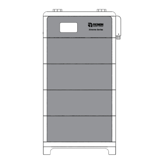
RENON, it can supply reliable power for nearly all kinds of household appliances and equipment. The Xtreme LV series consists of a main controller and several battery modules, each battery module has a built-in BMS battery management system, which can... -
Page 11: Specifications
2.2 Specifications R-XL010021 R-XL015031 R-XL020041 R-XL025051 R-XL030061 Item (-H) (-H) (-H) (-H) (-H) Controller Model R-MC300-XTL01 Battery Module Model R-EM51100-XTL01 (-H) Battery Chemistry LiFePO4 Module Quantity Nominal Energy (kWh) 10.24 15.36 20.48 25.60 30.72 Nominal Capacity (Ah) Max. Charging/Discharging Current (A) Nominal Voltage (V) 51.2 Recommend Charging... -
Page 12: Interface Information
2.3 Interface Information Figure 2.3.1. Interface definition of Controller module Instructions Instructions On/Off Inverter Communication Port (RJ45) WIFI Antenna Port Debug Port Inverter Dial Switch Parallel Communication Port A Address Dial Switch Parallel Communication Port B Function Dial Switch Power Negative Inverter Communication Port Power Positive (connector) -
Page 13: Inverter Dial Switch
2.3.3 Inverter Dial Switch Code 0 ~ 16 of this Dial Switch are used to match which brand of inverter is using. The definitions of code 0 ~ 16 are shown as below table. Code Dial Switch Position Brand Logo (Set by software) (Reserved) Schneider Gateway... -
Page 14: Address Dial Switch
MEGAREVO 2.3.4 Address Dial Switch 1) Use this Dial Switch to set the address of each master controller and then turn on to activate the system when it needs to be in parallel with other stack units. 2) When the system only has one stack set, dial the address to Cluster 1. 3) When the system used in parallel mode, set the address start from 1 and increased by the number of stack units in order to communicate with other stacks. - Page 15 Set as Cluster 11 Set as Cluster 12 Set as Cluster 13 Set as Cluster 14 Set as Cluster 15 Set as Cluster 16 Set as Cluster 17 Set as Cluster 18 Set as Cluster 19 Set as Cluster 20 Set as Cluster 21 Set as Cluster 22 Set as Cluster 23...
-
Page 16: Function Dial Switch
2.3.5 Function Dial Switch Use this dial switch to match the communication impedance, should set as below: Optimize and enhance the communication between the master control unit and the battery so as to communicate between paralleled clusters. Code Dial Code Switch Position Definition ①... -
Page 17: Inverter Communication Port (Rj45)
communication and used for an uncommitted digital signal pin on an integrated circuit or electronic circuit (e.g. MCUs/MPUs ) board which may be used as an input or output, or both, and is controllable by software. Defined as below: 6pin Terminal Usage GPI_1+ GPI_1-... -
Page 18: Debug Port
2.3.9 Debug Port Terminal type: RJ45 Usage: debug port of the system which used by technician only. Port definitions RJ45 Pin Function Debug.RS485-B Debug.RS485-A Debug.RS485-GND Debug.CANGND Debug.CANGND Debug.RS485-GND Debug.CANH Debug.CANL 2.3.10 Parallel Communication Port A & B Terminal type: RJ45 *2 Usage: Link A &... -
Page 19: Power Negative
2.3.11 Power Negative Terminal type: Terminal for 70 mm² power cable Usage: connect to inverter’s negative terminal. 2.3.12 Power Positive Terminal type: Terminal for 70 mm² power cable Usage: connect to inverter’s positive terminal. FM-RD-52 EN/V1.0... -
Page 20: Installation And Usage
3 Installation and Usage 3.1 Safe Handling Guide 3.1.1 Familiar with the product Be careful when unpacking the system. Every module of the product is heavy. Don't lift them with a pole. The weight of the modules can be found in the chapter "Specifications". -
Page 21: Safety Gear
Use properly insulated tools to prevent accidental electric shock or short circuits. If insulated tools are not available, cover the entire exposed metal surfaces of the available tools, except their tips, with electrical tape. 3.1.4 Safety Gear It is recommended to wear the following safety gear when dealing with the product: Insulated gloves Safety goggles... -
Page 22: Installation Location
3.3 Installation location Make sure that the installation location meets the following conditions: ●The floor is flat and level. ●The surface of the wall is smooth and perpendicular to the ground, which can bear the weight. ●The area is completely water proof. ●The area shall avoid direct sunlight. - Page 23 Main controller: Item Specification Usage Diagram Main Controller of the battery R-MC300-XTL01 controller cluster 25.0*9.4*5.7inches Bottom base of the battery Base /635*238*145mm cluster Mounted at the rear of the Mounting 4.3*3.1*2.8inches controller, used to stabilize bracket A /110*80*70mm the cluster Combine the mounting Mounting 1.6*3.1*0.9inches...
-
Page 24: Installation
3.5 Installation 1) Preparation of master controller: Fastened 2 mounting brackets A to the top back of the controller and screw those properly. Figure 3.5.1. Fastened the mounting bracket A 2) Preparation of the controller module: Fastened 2 mounting brackets B to mounting bracket A and screw those properly. - Page 25 4) Fasten the 4 mounting holes of the base on the floor in a stable condition. Figure 3.5.4. Mounting holes of the base 5) Stack up the battery modules, and then place the master controller unit on the top finally. Figure 3.5.5.
- Page 26 6) Fasten the 6 mounting holes of the mounting bracket B on the wall in a stable condition. Figure 3.5.6. Mounting holes of the base 7) Screw the groove plate to the side of each battery modules and make sure it is attached to the side and screw properly.
-
Page 27: Connections Of Cable And Power
8) Connect the ground wire as the diagram shown below. Figure 3.5.8. Ground wire connection 3.6 Connections of Cable and Power 1) Remove the side cover case. Figure 3.6.1. Removal position of the battery control module FM-RD-52 EN/V1.0... - Page 28 2) Set the Address dial code as 1 and set the function dial code as 32 in binary formation. Figure 3.6.2. Dial code 3) Remove the cover of the positive and the negative electrode. Connect the battery positive and negative electrode with the inverter's positive and negative electrode separately and then connect CAN/RS485 wire to the inverter port of the master controller and inverter's CAN/RS485 port.
-
Page 29: Wi-Fi Configuration
Screw the antenna into the antenna connection port firmly before Wi-Fi configuration. Figure 3.7.1. WIFI wiring position 1) Download and install RENON APP from Google or Apple Store by searching R-Cloud. Figure 3.7.2. Install RENON APP 2) You may acquire the Register Code from your installer for new account registration. - Page 30 Figure 3.7.3. Sign in 3) Turn to the page account then click the Network, following by the instruction of network setting for WIFI configuration. Figure 3.7.4. Network Setting 4) Connect your mobile phone to the WI-FI hotspot from the master controller which SSID is same as controller's serial number (SN) and the password is 12345678.
- Page 31 Figure 3.7.5. Connecting WIFI Hotspot of Product 5) Enter the SSID and password of your private WI-FI for connecting master controller to your private WI-FI. Make sure the Wi-Fi symbol on screen will shine constantly. Figure 3.7.6. Connecting Private WIFI 6) Ask your installer to assign all your products to your account.
- Page 32 Figure 3.7.7. Create A New Plant 8) Click the confirm button to create your plant and all your products will show up as their SN, select proper products and confirm. Figure 3.7.8. Manage Your Plant & Confirm Your Products 9) Now you can manage your products in the APP, and you can also manage them in Website, ask your installer for the site URL.
- Page 33 Figure 3.7.9. Manage Your Products 10) After the product is connected to Wi-Fi, the running status, real-time power, daily power consumption and cumulative power of the product can be monitored in real time on the network platform or mobile APP. It can also be used to configure parameters Figure 3.7.10.
-
Page 34: Paralleled Connection (Optional)
3.8 Paralleled connection (Optional) 1) Plan the distance between the two units and no less than 12inches(300mm), and 20inches(500mm) is recommended. Figure 3.8.1. The distance between two adjacent equipment 2) Before the parallel, every cluster's main controller inverter code needs to distinguish the number of battery modules for each cluster. -
Page 35: Monitoring Screen
Figure 3.8.2. Diagram of the cables connection between two adjacent equipment 5) Set the first cluster and the last cluster of the system's function dial code as code 33 and set function dial code of the rest of clusters as code 32. 6) Make sure all clusters are turned on except first one. -
Page 36: Soc, Soh And Upgrading State
Figure 4.1 LCD Screen Introduction Instructions SOC, SOH and Upgrading State Version and Accumulated Discharge Energy ESS status, Power, and Voltage Battery Operation State 4.2 SOC, SOH and Upgrading State 1) The percent number displays current SOC when underneath SOC sign lights on and current SOH when underneath SOH sign lights on, respectively. -
Page 37: Version And Accumulated Discharge Energy
4.3 Version and Accumulated Discharge Energy The number shows version of software and hardware for LCD, master, and slave, accumulated discharged energy counted in kWh or MWh, respectively. Each part will keep showing on for 3 seconds and then switch to next. 4.4 ESS status, Power, and Voltage 1) The number displays current power and volage of whole battery stacks. -
Page 38: Troubleshooting & Maintenance
5 Troubleshooting & Maintenance 5.1 Regular maintenance 1) Check the battery modules every 3 months to verify whether there are damages. 2) Check the battery modules every 3 months to verify whether the operating parameter is normal or there is no abnormal heating. 3) Fully charge and discharge the battery system every 3 months. -
Page 39: Troubleshooting
5.2 Troubleshooting Phenomenon Investigation & troubleshooting The number of battery module Make sure the whole battery system being stacked neatly. symbol is incorrect. Try to restart the battery system. The symbol of battery modules on Make sure the whole battery system being stacked neatly. the screen is blinking (frequency of Make sure the function dial switch code setting is correct, please refer to chapter “function dial switch”. - Page 40 Make sure the connection of communication cable and power cable is correct, refer to the chapter of connection of cable and power. Unable to communicate with Make sure the address dial code of the master controller inverter connected to inverter is 1. Make sure the inverter dial code of the master controller connected to inverter is correct, refer to the chapter of inverter dial code.
-
Page 41: Warning Codes
5.3 Warning Codes � � Warning Code (Sign like “� ”) Code Warning type Investigation & troubleshooting Low cell voltage discharge Low voltage level and needs to be charged protection Restore to factory setting. Overcurrent charge protection Make sure the inverter’s setting of max current do not excess the max charge current of the battery. -
Page 42: Error Codes
5.4 Error Codes Error Code (Sign like “ERR”) Code Error Type Investigation & troubleshooting Make sure the external connection for both battery and inverters are proper. Short circuit detected Disconnect all external connections and restart the battery Restart the battery and check whether the problem is Discharge circuit failure solved.
Need help?
Do you have a question about the Xtreme LV Series and is the answer not in the manual?
Questions and answers