
Subscribe to Our Youtube Channel
Related Manuals for Conductix-Wampfler ST-87 Series


Summary of Contents for Conductix-Wampfler ST-87 Series
- Page 1 Controller description ST-87x / ST-88x Vehicle controller STB_0005_ST-87x_ST-88x www.conductix.com...
- Page 2 Conductix-Wampfler Automation GmbH Handelshof 16 A 14478 Potsdam Germany Telephone: +49 (0) 331 887344-0 Fax: +49 (0) 331 887344-19 Email: info.potsdam@conductix.com Internet: www.conductix.com Translation of the original STB_0005, 7, en_GB © 2023 Conductix-Wampfler Automation GmbH...
-
Page 3: Table Of Contents
Series 8..................25 87x / 88x series model name............25 87x / 88x series power classes............ 25 87x / 88x series scope of functions..........25 Type label..................26 ST-87x / 88x designs..............27 Basic device................28 Transport and storage................29 Transport..................29 ST-87x /ST-88x Conductix-Wampfler Automation GmbH / 04/2023... - Page 4 Earthing the control system............65 Commissioning..................67 Notes about commissioning............70 Requirements................71 Commissioning procedure............72 Switch on control system............. 73 Assign control system parameters..........75 8.5.1 Vehicle parameters and configuration switches......76 ST-87x /ST-88x Conductix-Wampfler Automation GmbH / 04/2023...
- Page 5 Faults......................111 10.1 Displaying faults and errors............111 10.2 Error messages................. 112 10.3 Error codes................112 10.4 Fault types................. 113 10.5 Fault reset.................. 114 Service and maintenance............... 117 11.1 Maintenance and cleaning............117 ST-87x /ST-88x Conductix-Wampfler Automation GmbH / 04/2023...
- Page 6 Inverter..................142 14.4.5 Control circuit................143 14.4.6 ST-87x/88x Current Monitor............143 14.4.6.1 Hardware short circuit shutdown.......... 143 14.4.6.2 t-monitor (maximum load integral)........143 14.4.6.3 Software-based shutdown in the event of excess current..145 ST-87x /ST-88x Conductix-Wampfler Automation GmbH / 04/2023...
- Page 7 Table of contents Customer service and addresses............147 Index......................149 ST-87x /ST-88x Conductix-Wampfler Automation GmbH / 04/2023...
- Page 8 Table of contents ST-87x /ST-88x Conductix-Wampfler Automation GmbH / 04/2023...
-
Page 9: Information On The Description
This description forms part of the product and must be accessible to all per- sons working with the product at all times. ST-87x /ST-88x Conductix-Wampfler Automation GmbH / 04/2023... -
Page 10: Applicable Documents
No claims shall be accepted for possible discrepancies. Brands The popular names, trade names, production descriptions, etc. used in this description may constitute trademarks even without special designations and as such may be subject to legal requirements. ST-87x /ST-88x Conductix-Wampfler Automation GmbH / 04/2023... -
Page 11: Warranty And Liability
All information and notes in this description have been compiled taking into account the applicable standards and regulations, the state of the art and our many years of knowledge and experience. Conductix-Wampfler Automation GmbH assumes no liability for damage and malfunctions during operation due to: Failure to comply with the description... - Page 12 Warranty and liability Limitation of liability ST-87x /ST-88x Conductix-Wampfler Automation GmbH / 04/2023...
-
Page 13: Safety Instructions
Only then can safe operation be guaranteed. Of course, all legally applicable general safety and accident prevention reg- ulations must be complied with. Conductix-Wampfler Automation GmbH assumes no liability for damage or accidents that were caused by non-observance of these safety notes. Warning concept This description contains notes that must be observed for your own per- sonal safety and to avoid property damage. -
Page 14: Signal Words
Warnings of the 'caution' group do not have a specific danger symbol. Warning signs Type of danger Warning – automatic start-up. Warning - danger of crushing. Warning – high-voltage. Warning – danger of falling. Warning – falling objects. Warning – hot surface. ST-87x /ST-88x Conductix-Wampfler Automation GmbH / 04/2023... -
Page 15: Suggestions And Recommendations
Safety instructions Warning concept > Suggestions and recommendations Warning signs Type of danger Warning – danger zone. 3.1.5 Suggestions and recommendations This symbol indicates important information to help you handle the product. ST-87x /ST-88x Conductix-Wampfler Automation GmbH / 04/2023... -
Page 16: Intended Use
Do not use the controller for the transportation of people or animals. Modifications and alterations For the purpose of avoiding hazards and for ensuring optimum perform- ance, any modifications, additions, or alterations to the controller require Conductix-Wampfler Automation GmbH's express consent. ST-87x /ST-88x Conductix-Wampfler Automation GmbH / 04/2023... -
Page 17: Responsibility Of The Operator
The system operator must ensure that the responsibilities for activities on the system are unambiguously defined and only adequately qualified personnel familiar with the operating and safety regulations are working on and with the control system. ST-87x /ST-88x Conductix-Wampfler Automation GmbH / 04/2023... -
Page 18: Personnel And Qualifications
Prior to commissioning, ensure that all safety equipment is installed and functioning properly. Prior to commissioning, ensure that parameter assignment on the control system has been performed correctly in accordance with the electrical and mechanical conditions of the system. ST-87x /ST-88x Conductix-Wampfler Automation GmbH / 04/2023... - Page 19 Staff undergoing instruction and training are allowed to perform activities on and with the control system under the constant supervision of a trained and qualified individual. ST-87x /ST-88x Conductix-Wampfler Automation GmbH / 04/2023...
-
Page 20: Special Hazards
Start/stop switch The start/stop switch does not disconnect the controller from the power supply. Dangerous voltage is present. The control system must be disconnected from the power supply when performing work on it. ST-87x /ST-88x Conductix-Wampfler Automation GmbH / 04/2023... -
Page 21: Safety Instructions For The System Operator And Manufacturer
Unsafe control functions Risk of crushing limbs, catching and dragging of loose items of clothing due to moving machine parts. Implement safe control functions within your system controller, if your security concept demands safe functions. ST-87x /ST-88x Conductix-Wampfler Automation GmbH / 04/2023... -
Page 22: Safety Devices
Before starting work, check whether the safety devices are fully func- tional and connected properly to the controller. Report any faulty safety devices immediately. Bring vehicles with defective safety equipment to a standstill immedi- ately. Get safety devices repaired immediately. ST-87x /ST-88x Conductix-Wampfler Automation GmbH / 04/2023... -
Page 23: Safe Isolation
The vehicle controller meets all the requirements of EN 61800-5-1 and pro- vides reliable isolation of electronic and power connections. To ensure safe isolation, all connected electrical circuits must meet the requirements for safe isolation. ST-87x /ST-88x Conductix-Wampfler Automation GmbH / 04/2023... - Page 24 Safety instructions Safe isolation ST-87x /ST-88x Conductix-Wampfler Automation GmbH / 04/2023...
-
Page 25: Product Description
3.0 kW / 8.0 A ST-873 ST-883 Tab. 1: 87x / 88x series power classes 87x / 88x series scope of functions 87x/88x-series control systems have the following scope of functions in the basic configuration: ST-87x /ST-88x Conductix-Wampfler Automation GmbH / 04/2023... -
Page 26: Type Label
4 Rated input voltage, rated input frequency, rated input current 5 Output voltage, output frequency, rated motor power 6 Protection type, protection class, short-circuit current 7 QR-Code (serial number) 8 CE marking 9 NRTL marking for NRTL-approved control systems ST-87x /ST-88x Conductix-Wampfler Automation GmbH / 04/2023... -
Page 27: St-87X / 88X Designs
No heat sink is necessary in the power classes 0 to 1. ST-873 and 883-type control systems are fitted with retaining brackets at the factory. ST-870 / ST-871 ST-872 ST-873 ST-880 / ST-881 ST-882 ST-883 Tab. 3: ST-87x / 88x designs ST-87x /ST-88x Conductix-Wampfler Automation GmbH / 04/2023... -
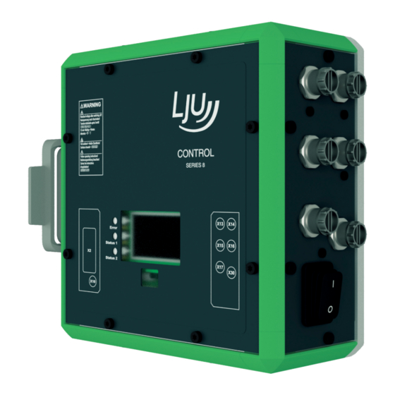
Page 28: Basic Device
BLDC motor monitoring port (ST-870, -871, -880, -881) Sensor/component port Start/stop switch Display Infra-red sensor/receiver Heat sink (ST-872, -873, -882, -883) External brake resistor (ST-872, -873, -882, -883) 10 Supply and data exchange port ST-87x /ST-88x Conductix-Wampfler Automation GmbH / 04/2023... -
Page 29: Transport And Storage
Initiate a complaints process and report the incident to the supplier. If Conductix-Wampfler Automation is your direct supplier you will find our contact information in this document. Ä Chapter ‘Customer service and addresses’ on page 147 Claims for damages Claim any defect as soon as it becomes apparent. -
Page 30: Storage
Keep the storage temperature as specified in the technical informa- tion. NOTICE! Storing control systems without supply voltage Connect devices to power supply for 5 minutes after max. 2 years of standstill. ST-87x /ST-88x Conductix-Wampfler Automation GmbH / 04/2023... -
Page 31: Mechanical Installation
Safety shoes Protective gloves Protective goggles Safety in the Note the safety signs in the area around the system. work area Pay attention to the safety notes in additional applicable documentation (supplier documents). ST-87x /ST-88x Conductix-Wampfler Automation GmbH / 04/2023... - Page 32 Danger of falling Danger of falling if the control system is mounted on typical assembly sites of a monorail. Provide safe ascent for all activities on the control system. Always use certified climbing aids. ST-87x /ST-88x Conductix-Wampfler Automation GmbH / 04/2023...
- Page 33 Mechanical installation L WARNING! Falling loads Risk of fatality due to falling objects Do not stand under loads. Seal off areas of mechanical installation. Seal off danger areas. ST-87x /ST-88x Conductix-Wampfler Automation GmbH / 04/2023...
-
Page 34: Open Spaces And Cooling
Ensure that the air around the device is constantly circulated. Do not place any flammable materials on top of the device. Keep flammable materials away from the housing surface and the heat sink. ST-87x /ST-88x Conductix-Wampfler Automation GmbH / 04/2023... - Page 35 Assembly of When installing control systems with heat sinks adequate circulation control sys- through the ambient air must be ensured. tems with heat sinks Fig. 4: Circulation through ambient air ST-87x /ST-88x Conductix-Wampfler Automation GmbH / 04/2023...
-
Page 36: Installation Position
Accessibility of the start/stop switch Ports accessible at all times 24° 24° Fig. 6: Angle of incidence of the infra-red receiver (optical field of vision) Data Value Unit Incidence angle Control system infra-red transmission range ST-87x /ST-88x Conductix-Wampfler Automation GmbH / 04/2023... -
Page 37: Installation
The vehicle control is intended for direct installation on the material-han- lation dling vehicle. ST-87x / ST-88x The 87x and 88x-type attachment points are located on the rear of the attachment device. points ST-87x /ST-88x Conductix-Wampfler Automation GmbH / 04/2023... - Page 38 160 mm 160 mm 160 mm Fig. 8: Dimensional drawing Alternative attachment points If the attachment points do not match those of the carrier unit, then other adapters are available for fixing upon request. ST-87x /ST-88x Conductix-Wampfler Automation GmbH / 04/2023...
-
Page 39: Installation With Direct Screw Connection
Max. screw depth 7 mm Tightening torque 2 Nm NOTICE! Threaded hole damage Exceeding the maximum tightening torque leads to damage to the thread. Only tighten screw connections with the specified tightening torque. ST-87x /ST-88x Conductix-Wampfler Automation GmbH / 04/2023... -
Page 40: Installation With Attachment Bracket
3 Cylinder screw Data Value Unit Tightening torque 2 Nm NOTICE! Threaded hole damage Exceeding the maximum tightening torque leads to damage to the thread. Only tighten screw connections with the specified tightening torque. ST-87x /ST-88x Conductix-Wampfler Automation GmbH / 04/2023... - Page 41 Fig. 11: Standard attachment bracket dims (mm) Alternative attachment points If the attachment points do not match those of the carrier unit, then other adapters are available for fixing upon request. ST-87x /ST-88x Conductix-Wampfler Automation GmbH / 04/2023...
- Page 42 Mechanical installation Installation > Installation with attachment bracket ST-87x /ST-88x Conductix-Wampfler Automation GmbH / 04/2023...
-
Page 43: Electrical Installation
Safety shoes Protective gloves Protective goggles Safety in the Note the safety signs in the area around the system. work area Pay attention to the safety notes in additional applicable documentation (supplier documents). ST-87x /ST-88x Conductix-Wampfler Automation GmbH / 04/2023... - Page 44 Risk of fatality posed by electric shock! The vehicle control system must be earthed. Connect the PE connection on the rear side of the device to the system PE in accordance with EN 60204-1. ST-87x /ST-88x Conductix-Wampfler Automation GmbH / 04/2023...
- Page 45 Danger of falling Danger of falling if the control system is mounted on typical assembly sites of a monorail. Provide safe ascent for all activities on the control system. Always use certified climbing aids. ST-87x /ST-88x Conductix-Wampfler Automation GmbH / 04/2023...
-
Page 46: Notes About Electrical Installation
7.1.1 Residual current circuit breaker and mains fusing Residual current circuit breakers react very quickly, which may lead to the control system stopping frequently. Conductix-Wampfler Automation GmbH recommends not using them. L WARNING! Electric shock due to incorrect residual current circuit breaker The control system may cause direct current in the protective con- ductor. - Page 47 The motor phase voltages are periodically switched between the posi- tive and negative intermediate circuit voltage with the switch frequency of the inverter (usually 16 kHz). Voltage pulses (PWM) of varying lengths result. Motor inductances form sinus-like currents from this. ST-87x /ST-88x Conductix-Wampfler Automation GmbH / 04/2023...
-
Page 48: Emc Installation Notes
The effectiveness of the EMC measures requires professional implementation. Even minor deviations from installation specifications could totally nullify their effectiveness. Cables Only use shielded motor cables with external shielding made from copper braiding. ST-87x /ST-88x Conductix-Wampfler Automation GmbH / 04/2023... - Page 49 M12 connector on the control system, and only use cables with wires twisted in pairs. Only connect external components with digital interfaces (position readers, distance measurers, etc.) to the control system using shielded cables. ST-87x /ST-88x Conductix-Wampfler Automation GmbH / 04/2023...
- Page 50 Not recommended Recommended Free-floating cables Free-floating cables work as active and passive antennae! Earth Unused cables must be earthed at both ends. ST-87x /ST-88x Conductix-Wampfler Automation GmbH / 04/2023...
- Page 51 ST-87x /ST-88x Conductix-Wampfler Automation GmbH / 04/2023...
-
Page 52: Cable Routing
The vehicle control systems are only suitable for operating motors (ohmic-inductive loads). Observe permissible motor sizes and cable lengths. Do not connect any capacities. Capacitive loads increase switching losses and may destroy transistors. ST-87x /ST-88x Conductix-Wampfler Automation GmbH / 04/2023... -
Page 53: Protective Measures
Control system contact line PE connection Vehicle frame contact line PE connection Fig. 14: Direct grid feed (diagram) 1 Overhead monorail rail with PE conductor 2 Overhead monorail vehicle 3 Vehicle control system 4 Motors 5 Vehicle earth ST-87x /ST-88x Conductix-Wampfler Automation GmbH / 04/2023... -
Page 54: Connecting The Electrical Parts Of The Control System
M12 plug connectors. Secure plug connections against accidental loosening by means of appropriate safeguards (brackets, screw caps). Do not connect cables to the vehicle control system under tension. Use strain reliefs. ST-87x /ST-88x Conductix-Wampfler Automation GmbH / 04/2023... - Page 55 Electrical installation Connecting the electrical parts of the control system Connection diagram Observe the [ANS] connection diagram supplied with your control system. ST-87x /ST-88x Conductix-Wampfler Automation GmbH / 04/2023...
-
Page 56: Electrical Connections
Brake Temperature sensor ST-870 / ST-871 Encoder For PMS/BLDC motor Encoder ST-880 / ST-881 Thermal protection ST-872 / ST-873 Brake resistor External brake resistor ST-882 / ST-883 Sensors Sensors LJU bus nodes etc. ST-87x /ST-88x Conductix-Wampfler Automation GmbH / 04/2023... -
Page 57: X1 - Supply
6.3 mm 8-pole Configuration Rail bus PCM / HW / Z-stop Signal Signal Phase L1 Phase L1 Phase L2 Phase L2 Phase L3 Phase L3 Unassigned S1 commands Unassigned M messages SB_A Z1 Z-stop ST-87x /ST-88x Conductix-Wampfler Automation GmbH / 04/2023... -
Page 58: X2 - Motor
Damage to or malfunctions of the drive unit when connection motors with integrated brake rectifier. Use motors without brake rectifier. Remove brake rectifiers subsequently. Function Connection type Connection image Motor Harting HAN10B HAN10E use Configuration Signal Function Unassigned Unassigned B1 + Brake ST-87x /ST-88x Conductix-Wampfler Automation GmbH / 04/2023... -
Page 59: X10 - Bldc Motor Encoder
X10 - BLDC motor encoder Function Connection type Connection image BLDC motor encoder M12 socket 8-pole A-coded Configuration Signal Function + 5 V DC Supply Thermal protection Encoder Encoder Encoder Thermal protection Switch Brake monitoring ST-87x /ST-88x Conductix-Wampfler Automation GmbH / 04/2023... -
Page 60: X10 - Brake Resistance
Brake resistor voltage Unassigned Tab. 8: X10 pin assignment 7.3.6 X13 - Sensors Function Connection type Connection image Sensors M12 socket 5-pole A-coded Configuration Signal Function + 24 V DC Supply Do not use ST-87x /ST-88x Conductix-Wampfler Automation GmbH / 04/2023... -
Page 61: X14 - Sensors
Digital IN 5 V configuration assignment Signal Function + 24 V DC Supply + 5 V DC Digital IN + 5 V DC Digital IN Do not use Tab. 10: X14 pin assignment ST-87x /ST-88x Conductix-Wampfler Automation GmbH / 04/2023... -
Page 62: X15 - Sensors
Connection image Sensors M12 socket 5-pole A-coded Assignment for configuration for digital IN Signal Function + 24 V DC Supply + 24 V DC Digital IN + 24 V DC Digital IN Unassigned ST-87x /ST-88x Conductix-Wampfler Automation GmbH / 04/2023... -
Page 63: X17 - Sensors
5-pole A-coded Configuration Signal Function + 24 V DC Supply + 24 V DC Digital OUT + 24 V DC Digital IN + 24 V DC Digital OUT Tab. 13: X17 pin assignment ST-87x /ST-88x Conductix-Wampfler Automation GmbH / 04/2023... -
Page 64: X30 - Usb
Tab. 14: X30 pin assignment NOTICE! USB connection Connecting unapproved devices may lead to damage to the control system or the connected device. Only connect devices approved by Conductix-Wampfler Automation GmbH to the USB port. ST-87x /ST-88x Conductix-Wampfler Automation GmbH / 04/2023... -
Page 65: Earthing The Control System
Earth wire or braided copper strip Conductor cross section ≥ 2.5 mm (AWG 14) Like the wire cross section of L1, L2, L3 at a minimum! Tab. 15: ST-87x / 88x PE connection ST-87x /ST-88x Conductix-Wampfler Automation GmbH / 04/2023... - Page 66 Electrical installation Earthing the control system ST-87x /ST-88x Conductix-Wampfler Automation GmbH / 04/2023...
-
Page 67: Commissioning
Personnel required for commissioning: Staff of Conductix-Wampfler Automation GmbH Sufficiently trained specialist personnel Required per- The person responsible must ensure that the personnel under his responsi- sonal protec- bility are wearing the required personal protective equipment. - Page 68 L WARNING! Missing protective coverings Risk of fatality posed by electric shock! Install missing protective coverings in compliance with regulations. Replace damaged protective coverings. Do not put control system into operation without protective coverings. ST-87x /ST-88x Conductix-Wampfler Automation GmbH / 04/2023...
- Page 69 / training of personnel. Keep clear of moving system parts. Do not reach into the running machine. Wear tight-fitting work clothes. Pay attention to optical and acoustic warning equipment. ST-87x /ST-88x Conductix-Wampfler Automation GmbH / 04/2023...
-
Page 70: Notes About Commissioning
[FDA0] on the display of the vehicle control system (following activation). The correct functioning of the control system is only ensured once the oper- ating parameters based on the mechanical and electrical conditions of the system have been entered. ST-87x /ST-88x Conductix-Wampfler Automation GmbH / 04/2023... -
Page 71: Requirements
Requirements NOTICE! Pre-set parameter values Control systems are subjected to testing by Conductix-Wampfler Auto- mation GmbH before delivery. In this process, the software is installed and test parameters are set. The pre-set parameter values are not customer-specific and may differ considerably from system-specific parameter values. -
Page 72: Commissioning Procedure
Optimise settings Ä Chapter ‘Optimise settings’ on page 93 Adapt vehicle parameters to ambient conditions. Adapt configuration switches to ambient conditions. Adapt vehicle tables to ambient conditions. Control system is ready for operation. ST-87x /ST-88x Conductix-Wampfler Automation GmbH / 04/2023... -
Page 73: Switch On Control System
After switching on, the display shows the "Conductix" logo during the start activation delay period. The start delay is set in parameter [T0]. Error Status 1 Status 2 Fig. 16: Display during activation ST-87x /ST-88x Conductix-Wampfler Automation GmbH / 04/2023... - Page 74 Since there are not yet any parameters in the control system, error mes- sages are displayed after the start process. The [Error] LED flashes or lights up permanently. Ä Chapter ‘Status LEDs’ on page 100 ST-87x /ST-88x Conductix-Wampfler Automation GmbH / 04/2023...
-
Page 75: Assign Control System Parameters
Reference Information on the MU-705 Utility software can be found in the document: MU-705 Utility v2.x_PB0001.pdf This document is part of the project documentation and is available for download at www.conductix.com. ST-87x /ST-88x Conductix-Wampfler Automation GmbH / 04/2023... -
Page 76: Vehicle Parameters And Configuration Switches
BV, included in the scope of delivery! Parameter Positive values from 0 to a maximum 65535 can be set as parameter values values. The value range is limited further for some parameters. ST-87x /ST-88x Conductix-Wampfler Automation GmbH / 04/2023... -
Page 77: Creating And Saving Parameters And Configuration Switches
The [PAR] parameter (release key) is one exception. Editing and saving parameters and configuration switches with the MU-705 manual programming device: Open menu item "Parameters" à "Modify data". Edit parameters or configuration switches. ST-87x /ST-88x Conductix-Wampfler Automation GmbH / 04/2023... -
Page 78: Transferring Parameters And Configuration Switches
MU-705 manual programming device. Transferring parameters and configuration switches with the MU-705 manual programming device: Open menu item "Parameters" à "Write data". Press the F1 key [Yes] to confirm the 'Send' request. ST-87x /ST-88x Conductix-Wampfler Automation GmbH / 04/2023... - Page 79 In rail bus projects, it is also possible to edit, save and transfer parame- ters, configuration switches and tables to the vehicle control system using the iDM-SyMa (iDM system) or DKZ-Para (bus master system). Requirement: properly configured iDM system or bus master system ST-87x /ST-88x Conductix-Wampfler Automation GmbH / 04/2023...
-
Page 80: Vehicle Tables - Pcm System (St-87X/St-88X)
This is defined depending on the type of application or can be set through the PCM configuration table. Thanks to the variable configuration of a distance sensor, it is possible to implement various distances. ST-87x /ST-88x Conductix-Wampfler Automation GmbH / 04/2023... -
Page 81: Creating And Saving Vehicle Tables
For backups on a PC, it is recommended to use the MU-705 Utility program. 8.5.2.2 Transferring vehicle tables Vehicle tables are transferred to the vehicle control system using the MU-705 manual programming device. Vehicle tables Vehicle tables can be transferred individually or all together! ST-87x /ST-88x Conductix-Wampfler Automation GmbH / 04/2023... - Page 82 Open menu item "Tables" à "All tables" à "Write". Press the F1 key [Yes] to confirm the 'Send' request. Establish infrared communication. ð All tables are transferred from the MU-705 manual programming device to the vehicle control system. ST-87x /ST-88x Conductix-Wampfler Automation GmbH / 04/2023...
-
Page 83: Vehicle Tables - Rail Bus Sb (St-87X-Sb/St-88X-Sb)
Based on the system posi- tion, the vehicle control system identifies the current segment and proceeds at the specified speed. This allows the specification of various speeds for cornering, straight travel, etc. ST-87x /ST-88x Conductix-Wampfler Automation GmbH / 04/2023... -
Page 84: Creating And Saving Vehicle Tables
This ensures that the values in the MU-705 manual program- ming device match those in the vehicle control system. ST-87x /ST-88x Conductix-Wampfler Automation GmbH / 04/2023... -
Page 85: Transferring Vehicle Tables
Transferring all tables with the MU-705 manual programming device: Open menu item "Tables" à "All tables" à "Write". Press the F1 key [Yes] to confirm the 'Send' request. ST-87x /ST-88x Conductix-Wampfler Automation GmbH / 04/2023... - Page 86 In rail bus projects, it is also possible to edit, save and transfer parame- ters, configuration switches and tables to the vehicle control system using the iDM-SyMa (iDM system) or DKZ-Para (bus master system). Requirement: properly configured iDM system or bus master system ST-87x /ST-88x Conductix-Wampfler Automation GmbH / 04/2023...
-
Page 87: Configuring The Bus Communication (St-87X-Sb/St-88X-Sb)
Project-specific software description BVxxxxx, included in the scope of delivery Project-specific interface description BVxxxxx, included in the scope of delivery These documents contain all the information on the configuration settings of the bus communication. ST-87x /ST-88x Conductix-Wampfler Automation GmbH / 04/2023... -
Page 88: Test Control System
The drive can perform undesired movements if a different key is assigned on the hand-held remote control. Observe the remote control commands in the project-specific soft- ware description BV, included in the scope of delivery! ST-87x /ST-88x Conductix-Wampfler Automation GmbH / 04/2023... - Page 89 ð Opens mechanical brake (if available) Motor rotates During the test make sure that: The motor is rotating in the specified direction. The rated current is not exceeded. The motor overrun is quiet. ST-87x /ST-88x Conductix-Wampfler Automation GmbH / 04/2023...
-
Page 90: Test - Sensors And Peripherals
Ä Chapter ‘Display modes’ on page 104 Bus compo- Position encoders, distance sensors and vehicle address boxes can be nents test used as bus components. The bus components must support the LJU bus protocol. ST-87x /ST-88x Conductix-Wampfler Automation GmbH / 04/2023... -
Page 91: Test - Communication
In addition to correct wiring and parameter configuration, a requirement for registration is the existence of a valid position value (≠ 0) as well as a valid vehicle number (≠ 0). Communication is successful if the control system can be registered. ST-87x /ST-88x Conductix-Wampfler Automation GmbH / 04/2023... - Page 92 As an additional control option, it is possible to compare the command and status words of the TCU or bus master and the control system using dis- play mode 120 (PLC command A + B) and display mode 121 (PLC status A + B). ST-87x /ST-88x Conductix-Wampfler Automation GmbH / 04/2023...
-
Page 93: Optimise Settings
Settings are made in the parameters of the modes of movement (normal movement, ascent, descent, synchronous movement, special movement). ST-87x /ST-88x Conductix-Wampfler Automation GmbH / 04/2023... - Page 94 To compensate for this time shift, delay times can be set for commands with the parameters "PCM command – Command change delay" [TPc0] and [TPc]) and for components with the parameter "Detection delay time" [TDxx]. ST-87x /ST-88x Conductix-Wampfler Automation GmbH / 04/2023...
-
Page 95: Operation
Only work when protection and monitoring equipment are active. work area Pay attention to the safety signs at the work station and its immediate vicinity. Only load load-bearing machinery within the permitted limits. Secure goods to be transported against loss. ST-87x /ST-88x Conductix-Wampfler Automation GmbH / 04/2023... - Page 96 Wear tight-fitting work clothes. Pay attention to optical and acoustic warning equipment. L WARNING! Hazardous voltages on ports and cables Open electrical components Do not pull plugs carrying voltage. Do not contact open cables. ST-87x /ST-88x Conductix-Wampfler Automation GmbH / 04/2023...
-
Page 97: Operating Modes
Prior to working on the control system, allow the connected compo- nents to cool down. Operating modes Operating The control system can be operated in the following ways: modes Automatic mode Manual mode Unrestrained manual mode ST-87x /ST-88x Conductix-Wampfler Automation GmbH / 04/2023... -
Page 98: Switching The Control System On And Off
Switching the control system on and off 9.2.1 Switch on control system Automatic start-up After activation, the control system goes into automatic mode autono- mously Set start/stop switch to [I] ð The control system starts. ST-87x /ST-88x Conductix-Wampfler Automation GmbH / 04/2023... -
Page 99: Switches The Control System Off
Set start/stop switch to [0] Display during If the control system is switched off, the display shows the inverted "Con- shutdown ductix" logo. Error Status 1 Status 2 Fig. 18: Display during shutdown ST-87x /ST-88x Conductix-Wampfler Automation GmbH / 04/2023... -
Page 100: Displays
Flashing - LED flashes Control system has errors ✓ ✓ (on/off each time approx. 1 sec) Single flash - LED flashes Stop activated ✓ ✓ once Tab. 16: Display – LED – Error ST-87x /ST-88x Conductix-Wampfler Automation GmbH / 04/2023... - Page 101 Single flash - LED flashes Vehicle stops – Approach sensor ✓ ✓ once Double flash - LED flashes Vehicle stops – Distance sensor ✓ ✓ twice Tab. 18: Display – LED – Status 2 ST-87x /ST-88x Conductix-Wampfler Automation GmbH / 04/2023...
-
Page 102: Display
Display presen- Four lines each with the number of the display mode and its value are tation ‒ shown on the display by default. Which values are displayed can be config- Standard ured. ST-87x /ST-88x Conductix-Wampfler Automation GmbH / 04/2023... - Page 103 If the vehicle is in error mode, the error number and a red LED flash. Error number and error message are shown in alternation. If more than one error is active, the various numbers and messages are displayed one after the other. ST-87x /ST-88x Conductix-Wampfler Automation GmbH / 04/2023...
-
Page 104: Display Modes
Observe the project-specific software description BVxxxxx, included in the scope of delivery! This document contains all the information on the display modes. 9.3.3.1 Creating/modifying display modes Display modes are selected in the MU-705 manual programming device. ST-87x /ST-88x Conductix-Wampfler Automation GmbH / 04/2023... -
Page 105: Calculating And Evaluating Hexadecimal Values
To evaluate what the displayed number means, the number must be converted into binary format. Hexadecimal Binary 0000 0001 0010 0011 0100 0101 0110 0111 Hexadecimal Binary 1000 1001 1010 1011 1100 1101 1110 1111 ST-87x /ST-88x Conductix-Wampfler Automation GmbH / 04/2023... - Page 106 Bit 12 Set speed reached Bit 16 Stopped due to distance check Meaning of set bits The meaning of set or non-set bits can be found in the legend of the respective display mode. ST-87x /ST-88x Conductix-Wampfler Automation GmbH / 04/2023...
-
Page 107: Vehicle Remote Control
Reference For information about the manual programming device, please refer to the corresponding operating manual: BDA_0005_MU-705.pdf The operating manual is part of the project documentation or can be downloaded from www.conductix.com. ST-87x /ST-88x Conductix-Wampfler Automation GmbH / 04/2023... -
Page 108: Changing Operating Mode
ð The vehicle control system is in automatic mode. mode Activating Activate [SW12] configuration switch in the manual programming unrestrained device and transfer the new configuration to the vehicle control manual mode system. ST-87x /ST-88x Conductix-Wampfler Automation GmbH / 04/2023... -
Page 109: Moving The Vehicle Manually
Function Switchover to manual mode Switchover to automatic mode ↑ Release brake → Slow forwards movement → Fast forwards movement ← Slow forwards movement ← Fast backwards movement ST-87x /ST-88x Conductix-Wampfler Automation GmbH / 04/2023... - Page 110 Data is transferred via infra-red. For successful data transmission, the distance to the display of the control system and the IR receiver may be max. 1 m at an angle of 16°. ST-87x /ST-88x Conductix-Wampfler Automation GmbH / 04/2023...
-
Page 111: Faults
The error number is composed of a large "F" and a three-digit hexadecimal number. F110 Axis 1 break failure Error Status 1 002: 10000 002: 10000 Status 2 Fig. 25: Display – Error message Fault indicator can be deactivated through configuration switch [SW13]. ST-87x /ST-88x Conductix-Wampfler Automation GmbH / 04/2023... -
Page 112: Error Messages
0...9 / A...F Safety circuit fault 0...9 / A...F 0...9 / A...F Application error 0...9 / A...F 0...9 / A...F I/O system error 0...9 0...9 / A...F Communication error 0...9 / A...F 0...9 / A...F ST-87x /ST-88x Conductix-Wampfler Automation GmbH / 04/2023... -
Page 113: Fault Types
Faults whose cause or effect do not lead to personal injury or damage to edging faults the system acknowledge themselves provided the cause of the fault is no longer present. Self-acknowledging faults are saved in the error log. The error message is reset automatically – Self-reset. ST-87x /ST-88x Conductix-Wampfler Automation GmbH / 04/2023... -
Page 114: Fault Reset
After eliminating the cause of the fault, a present fault can be reset. Resetting faults: Manual Reset (MR) Power on Reset (POR) Self-Reset (SR) Manual Reset Change operating mode (MR) Confirm operating mode Press start/stop switch ST-87x /ST-88x Conductix-Wampfler Automation GmbH / 04/2023... - Page 115 The option Power on Reset Only use if the fault was not reset by pressing the start/stop switch. Ä ‘Self-acknowledging faults’ on page 113 Self-Reset (SR) Self-acknowledging fault Faults that reset themselves once the cause of the fault has been elimi- nated. ST-87x /ST-88x Conductix-Wampfler Automation GmbH / 04/2023...
- Page 116 Faults Fault reset ST-87x /ST-88x Conductix-Wampfler Automation GmbH / 04/2023...
-
Page 117: Service And Maintenance
Brackets Check for loose connections. Connections Check for loose connections. Check cable insulation. Cover any ports not being used. Indicators Remove soiling. Recommended maintenance interval 6 months ST-87x /ST-88x Conductix-Wampfler Automation GmbH / 04/2023... -
Page 118: Cleaning
Prior to commissioning, ensure that all safety equipment is installed and functioning properly. Prior to commissioning, ensure that parameter assignment on the device has been performed correctly in accordance with the electrical and mechanical conditions of the system. ST-87x /ST-88x Conductix-Wampfler Automation GmbH / 04/2023... -
Page 119: Control System Removal
Disconnect the power supply safely: Disconnect system from power Disconnect collector from busbar Waiting time after voltage isolation: At least 10 minutes Disconnect external connections. If available: Remove the DataCom stick. Disconnect mechanical connections. ST-87x /ST-88x Conductix-Wampfler Automation GmbH / 04/2023... -
Page 120: Control System Installation
(Configure vehicle number and type, if necessary.) 11.3 Repairing the control system If a repair of the control system becomes necessary, please refer to your next service partner or go directly to Conductix-Wampfler Automation GmbH. Ä Chapter ‘Customer service and addresses’ on page 147 Repairs... -
Page 121: Disposal
Follow the hazardous materials directive, in particular the regulations on handling hazardous materials. Materials designated for recycling are to be disposed of as per the respective recycling procedure. ST-87x /ST-88x Conductix-Wampfler Automation GmbH / 04/2023... - Page 122 Disposal Information on disposal and environmental regulations ST-87x /ST-88x Conductix-Wampfler Automation GmbH / 04/2023...
-
Page 123: Technical Specifications
3 Mounting plate 4 Edge profile 5 Front film Type Material Fig. 26/1 Aluminium Fig. 26/2 Plastic ABS, green Fig. 26/3 Aluminium Fig. 26/4 Aluminium Fig. 26/5 Polyethylene Tab. 21: ST-87x / 88x material ST-87x /ST-88x Conductix-Wampfler Automation GmbH / 04/2023... - Page 124 1,000 m above mean sea level height Without derating Relative humidity < 80% non-condensing Storage temperature -10–+50 ºC Protection class Protection class IP54 Except port X1 EMC conformity (Interfer- EN 61800-3-compliant ence suppression) Category C2 ST-87x /ST-88x Conductix-Wampfler Automation GmbH / 04/2023...
-
Page 125: Input Data
Current consumption 3 mA typical Input frequency 50 / 60 Hz (± 5%) synchronous to the grid *Measured against the reference phase of the inputs. Tab. 26: ST-87x / 88x - Half-wave/PCM input ST-87x /ST-88x Conductix-Wampfler Automation GmbH / 04/2023... -
Page 126: Output Data
External Axis data ST-870 ST-871 ST-872 ST-873 ST-880 ST-881 ST-882 ST-883 Rated motor power 0.75 kW 1.5 kW 2.2 kW 3.0 kW Rated output current 2.5 A 4.2 A 6.0 A 8.0 A ST-87x /ST-88x Conductix-Wampfler Automation GmbH / 04/2023... - Page 127 < DC 1 V NOTICE! Excessive total current of external consumers The total current of all external 24 V consumers at the digital outputs and the RS485 interface must not exceed 1.0 A. ST-87x /ST-88x Conductix-Wampfler Automation GmbH / 04/2023...
-
Page 128: Interfaces
Incidence angle 48º Control system transmission range 13.5 Cable lengths and specifications Connection between: Cable length Specification Overhead monorail rails, L1, L2, L3, Vehicle control ≥ 2.5 mm ≤ 2 m system (AWG 14) ST-87x /ST-88x Conductix-Wampfler Automation GmbH / 04/2023... -
Page 129: Approvals And Standards
13.6 Approvals and standards Conformity Devices made by Conductix-Wampfler Automation GmbH have been designed to comply with EU directives. Please contact Conductix-Wampfler Automation GmbH if you wish to obtain a copy of the EU Declaration of Conformity. Certifications Controllers of the types ST-87x / ST-88x are tested and certified as follows:... - Page 130 Technical specifications Approvals and standards ST-87x /ST-88x Conductix-Wampfler Automation GmbH / 04/2023...
-
Page 131: Information And Parameter Assignment
If the rated frequency and the pole pair number of the motor are known, then the synchronous speed can be calculated (n = ( f ✕ 60 ) / p f = Frequency [Hz] = Synchronous speed [rpm] p = Pole pair number ST-87x /ST-88x Conductix-Wampfler Automation GmbH / 04/2023... -
Page 132: How It Works
This leads to an increase to the intermediate circuit voltage of the frequency converter. Once the intermediate circuit voltage reaches a particular volume, a braking resistor is activated which converts the excess energy into heat. ST-87x /ST-88x Conductix-Wampfler Automation GmbH / 04/2023... - Page 133 (< 15 Hz). This rise is referred to as IxR compensation. The illustration below shows the actual U/f curve with a set voltage rise and the resulting torque. ST-87x /ST-88x Conductix-Wampfler Automation GmbH / 04/2023...
- Page 134 (q). The 8-series frequency converters can regulate the control of the three- phase current asynchronous motors; both sensor-guided and sensor- less. ST-87x /ST-88x Conductix-Wampfler Automation GmbH / 04/2023...
-
Page 135: Permanent Magnet Synchronous Motor
14.2.1 Layout and function Like the three-phase current asynchronous motor, the permanent magnet synchronous motor consists of a stationary stator and the rotation-mounted rotor. ST-87x /ST-88x Conductix-Wampfler Automation GmbH / 04/2023... -
Page 136: How It Works
The torque of the motor is equal to zero. The tightening force between the rotary field pole and the rotor pole may be at the maximum, but no effective moment arm is produced. ST-87x /ST-88x Conductix-Wampfler Automation GmbH / 04/2023... - Page 137 If the frequency converter can supply a higher voltage, the speed can be increased further (7). This leads to a higher power at a constant torque. If the voltage has reached an upper limit, the motor crosses over into the field-weakening range (88). ST-87x /ST-88x Conductix-Wampfler Automation GmbH / 04/2023...
-
Page 138: Parameters For The Settings Of The Controlled Operation
The parameters which have a significant influence on the behaviour of the frequency converter and the motor in uncontrolled operation are: Drive Motor - Type Motor - Rated current Motor - Rated voltage ST-87x /ST-88x Conductix-Wampfler Automation GmbH / 04/2023... -
Page 139: Parameters For The Settings Of Controlled Operation (Vector Control)
All parameters for uncontrolled operation Following table Motion Kpf_ Flow regulator proportional gain Tnf_ Flow regulator integral time KpVK Speed regulator proportional gain, pre-decimal point KpNK Speed regulator proportional gain, post-decimal point Tnd_ Speed regulator integral time ST-87x /ST-88x Conductix-Wampfler Automation GmbH / 04/2023... -
Page 140: Brushless Dc Motors
However, a frequency converter guarantees excellent operating conditions across the entire operating range by adapting its output values (voltage, frequency) to the current load condi- tions. ST-87x /ST-88x Conductix-Wampfler Automation GmbH / 04/2023... -
Page 141: Layout And Function
3✕400 V / 50 Hz). The rectifier is connected to this supply voltage and generates a pulsating DC voltage. 14.4.3 Intermediate circuit The task of the intermediate circuit is to: Smoothing the pulsating DC voltage of the rectifier Power reserve in case of voltage supply loss ST-87x /ST-88x Conductix-Wampfler Automation GmbH / 04/2023... -
Page 142: Inverter
0,866 0,50 0,50 0,866 Fig. 36: PWM output voltage 1 PWM signal 2 Phase voltage (phase star point) 3 Chained voltage ST-87x /ST-88x Conductix-Wampfler Automation GmbH / 04/2023... -
Page 143: Control Circuit
As the energy cannot be measured directly, the product is monitored using RMS and time. The product is proportional to the volume of energy. ST-87x /ST-88x Conductix-Wampfler Automation GmbH / 04/2023... - Page 144 For i_eff = 10 A would result in t_fault = t_max = 1 s. 14.4.6.2.1 Motor I t-monitor The following motor parameters are relevant: [In_] (nominal motor current) [Imx_] (maximum current) [TIm_] (time to excess current) ST-87x /ST-88x Conductix-Wampfler Automation GmbH / 04/2023...
-
Page 145: Software-Based Shutdown In The Event Of Excess Current
Software-based shutdown in the event of excess current If the effective current of the converter exceeds 20 A for 100 ms, the con- verter is powered down to the highest deceleration ramp before stopping with fault [F018] (current). ST-87x /ST-88x Conductix-Wampfler Automation GmbH / 04/2023... - Page 146 Information and parameter assignment Frequency converters > ST-87x/88x Current Monitor ST-87x /ST-88x Conductix-Wampfler Automation GmbH / 04/2023...
- Page 147 Rheinstrasse 27 + 33 | 79576 Weil am Rhein | Germany Phone: +49 7621 662-0 | Fax: +49 7621 662-144 E-mail: info.de@conductix.com | Internet: www.conductix.com For further addresses of sales and service locations, visit: www.conductix.com ST-87x /ST-88x Conductix-Wampfler Automation GmbH / 04/2023...
- Page 148 Customer service and addresses ST-87x /ST-88x Conductix-Wampfler Automation GmbH / 04/2023...
- Page 149 Dimensions..........123 Quadrature inputs........ 126 Display............36 Z-stop........... 126 Extended..........103 Installation..........39, 40 Fault indicator....... 103, 111 Installation position........36 Infra-red communication...... 103 Intended use..........16 Standard..........102 Distance table........80, 84 ST-87x /ST-88x Conductix-Wampfler Automation GmbH / 04/2023...
- Page 150 Status LEDs..........100 X10 BLDC motor........59 Stop-offset table......... 84 X10 brake resistor........60 Storage............30 X13............60 Switches the control system off....99 X14............61 Switch on control system...... 73, 98 X15............62 ST-87x /ST-88x Conductix-Wampfler Automation GmbH / 04/2023...
- Page 151 Vehicle tables..... 80, 81, 83, 84, 85 Warranty............. 11 Weight............124 X1............56, 57 X10..........56, 59, 60 X13............56, 60 X14............56, 61 X15............56, 62 X16............56, 62 X17............56, 63 X2............56, 58 X30............56, 64 ST-87x /ST-88x Conductix-Wampfler Automation GmbH / 04/2023...
Need help?
Do you have a question about the ST-87 Series and is the answer not in the manual?
Questions and answers