Table of Contents
Advertisement
Available languages
Available languages
Quick Links
2-Cycle Gasoline Trimmer
CC2020
TM
S t a r t i n g
TABLE OF CONTENTS
Service Information . . . . . . . . . . . . . . . . . . . . . . . . . . . . . .1
Rules for Safe Operation . . . . . . . . . . . . . . . . . . . . . . . . . .2
Oil and Fuel Information . . . . . . . . . . . . . . . . . . . . . . . . . . .4
Know Your Unit . . . . . . . . . . . . . . . . . . . . . . . . . . . . . . . . .4
Assembly Instructions . . . . . . . . . . . . . . . . . . . . . . . . . . . .5
Starting/Stopping Instructions . . . . . . . . . . . . . . . . . . . . . .7
Operating Instructions . . . . . . . . . . . . . . . . . . . . . . . . . . . .8
Maintenance and Repair Instructions . . . . . . . . . . . . . . . . .9
Cleaning and Storage . . . . . . . . . . . . . . . . . . . . . . . . . . . .12
Troubleshooting Chart . . . . . . . . . . . . . . . . . . . . . . . . . . .13
Specifications . . . . . . . . . . . . . . . . . . . . . . . . . . . . . . . . . .14
Warranty Information . . . . . . . . . . . . . . . . . . . . . . . . . . . .16
P/N 769-04652 P00
Operator's Manual
DO NOT RETURN
THIS PRODUCT
For Assistance please call 1-877-282-8684 (U.S.) or
1-800-668-1238 (Canada)
or visit www.cubcadet.com / www.cubcadet.ca
SAVE THESE INSTRUCTIONS
For service call 1-877-282-8684 in the United States, or
1-800-668-1238 in Canada to obtain a list of authorized service
dealers near you. For more details about your unit, visit our
website at www.cubcadet.com or www.cubcadet.ca.
DO NOT RETURN THE UNIT TO THE RETAILER. PROOF
OF PURCHASE WILL BE REQUIRED FOR WARRANTY
SERVICE.
THIS PRODUCT IS COVERED BY ONE OR MORE U.S.
PATENTS. OTHER PATENTS PENDING.
Service on this unit both within and after the warranty period
should be performed only by an authorized and approved
service dealer.
Before beginning, locate the unit's model plate. It lists the
model and serial numbers of your unit. Refer to the sample
plate below and copy the information for future reference.
S/N :
Copy the model and parent part number here:
Copy the serial number here:
All information, illustrations, and specifications in this manual are
based on the latest product information available at the time of
printing. We reserve the right to make changes at any time
without notice.
Copyright© 2009 MTD SOUTHWEST INC, All Rights Reserved.
®
MODEL :
ITEM :
(01/09)
Advertisement
Chapters
Table of Contents

Related Manuals for Cub Cadet CC2020


Summary of Contents for Cub Cadet CC2020
- Page 1 ® Operator’s Manual 2-Cycle Gasoline Trimmer CC2020 DO NOT RETURN THIS PRODUCT For Assistance please call 1-877-282-8684 (U.S.) or 1-800-668-1238 (Canada) or visit www.cubcadet.com / www.cubcadet.ca S t a r t i n g SAVE THESE INSTRUCTIONS For service call 1-877-282-8684 in the United States, or 1-800-668-1238 in Canada to obtain a list of authorized service dealers near you.
- Page 2 RULES FOR SAFE OPERATION SPARK ARRESTOR NOTE The purpose of safety symbols is to attract your attention to possible NOTE: For users on U.S. Forest Land and in the states of dangers. The safety symbols, and their explanations, deserve your California, Maine, Oregon and Washington.
- Page 3 RULES FOR SAFE OPERATION operating the unit as a trimmer. Do not operate unit without authorized service dealer. Use of any unauthorized parts or both trimming lines extended, and the proper line installed. Do accessories could lead to serious injury to the user, or damage not extend the trimming line beyond the length of the shield.
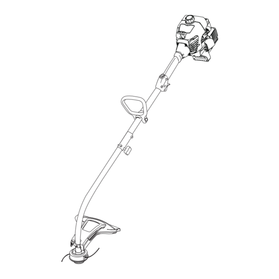
- Page 4 KNOW YOUR UNIT APPLICATIONS Fuel Cap As a trimmer: Starter Rope Grip • Cutting grass and light weeds. • Edging Shaft Grip • Decorative trimming around trees, fences, etc. Other optional accessories may be used with this unit. On/Off Stop Control Refer to Operating the EZ-Link System for a list of add-ons.
- Page 5 ASSEMBLY INSTRUCTIONS INSTALL AND ADJUST THE D-HANDLE INSTALL THE CUTTING HEAD SHIELD 1. Push the D-handle down onto the shaft housing (Fig. 1). WARNING: Never operate the trimmer without The squared bolt hole in the handle is to the right. the cutting head shield in place to prevent serious personal injury.
- Page 6 ASSEMBLY INSTRUCTIONS OPERATING THE EZ-LINK™ SYSTEM 2. While firmly holding the add-on, push it straight into the EZ-Link™ coupler (Fig. 7). The EZ-Link™ system enables the use of these optional Add- Ons: NOTE: Aligning the release button with the guide recess will help installation (Fig.
- Page 7 STARTING / STOPPING INSTRUCTIONS WARNING: Operate this unit only in a well- Stop/Off (O) ventilated outdoor area. Carbon monoxide exhaust fumes can be lethal in a confined area. Start/On ( I ) WARNING: Avoid accidental starting. Make sure you are in the starting position when pulling the starter rope (Fig.
- Page 8 OPERATING INSTRUCTIONS HOLDING THE TRIMMER NOTE: Do not rest the Bump Head™ on the ground while the unit is running. WARNING: Always wear eye, hearing, foot and Some line breakage will occur from: body protection to reduce the risk of injury when •...
- Page 9 MAINTENANCE AND REPAIR INSTRUCTIONS MAINTENANCE SCHEDULE Bolt WARNING: To prevent serious injury, never perform maintenance or repairs with unit running. Bump Knob™ Always service and repair a cool unit. Disconnect the spark plug wire to ensure that the unit cannot start. Perform these required maintenance procedures at the frequency stated in the table.
- Page 10 MAINTENANCE AND REPAIR INSTRUCTIONS Single Line Installation 12. Insert the ends of the line into the two holding slots (Fig. 22). Go To Step 8 for SplitLine™ Installation Take approximately 18 feet (5.4 m) of new trimming line, loop it into two equal lengths. Insert each end of the line through one of the two holes in the inner reel (Fig.
- Page 11 MAINTENANCE AND REPAIR INSTRUCTIONS AIR FILTER MAINTENANCE Removing the Air Filter/Muffler Cover WARNING: To avoid serious personal injury, always turn your unit off and allow it to cool before you clean or service it. Place the blue choke lever in Position 2. Remove the four (4) screws securing the air filter/muffler cover (Fig.
- Page 12 MAINTENANCE AND REPAIR INSTRUCTIONS 1. Stop the engine and allow it to cool. Grasp the plug wire CARBURETOR ADJUSTMENT firmly and pull the boot from the spark plug. The idle speed of the engine is adjustable through the air 2. Clean around the spark plug. Remove the spark plug from filter/muffler cover (Fig.
- Page 13 TROUBLESHOOTING ENGINE WILL NOT START C A U S E A C T I O N Empty fuel tank Fill fuel tank with properly mixed fuel Primer bulb wasn't pressed enough Press primer bulb fully and slowly 10 times Engine is flooded Place blue choke lever in position 3, squeeze the trigger and pull the starter rope Old or improperly mixed fuel...
- Page 14 SPECIFICATIONS ENGINE* Engine Type................................Air-Cooled, 2-Cycle Stroke ..................................1.25 in. (31.75 mm) Displacement .................................. 1.9 cu in. (31 cc) Clutch Type ....................................Centrifugal Idle Speed RPM ................................2,600 - 3,600 rpm Operating RPM ..................................6,800+ rpm Ignition Type....................................Electronic Ignition Switch ................................... Rocker Switch Spark Plug Gap ................................
- Page 15 NOTES...
- Page 16 MANUFACTURER’S LIMITED WARRANTY FOR: ® The limited warranty set forth below is given by Cub Cadet LLC No implied warranty, including any implied warranty of (“Cub Cadet”) with respect with new merchandise purchased merchantability or fitness for a particular purpose, applies and used in the United States, its possessions and territories.
-
Page 17: Table Of Contents
® Manuel de l'utilisateur Désherbeuse à gaz à 2-temps CC2020 NE RETOURNEZ PAS CE PRODUIT Pour une assistance, veuillez appeler le 1-877-282-8684 (E.U.) ou le 1-800-668-1238 (Canada) ou visitez : www.cubcadet.com / www.cubcadet.ca S t a r t i n g CONSERVEZ CES INSTRUCTIONS Obtenez la liste des concessionnaires agréés appelez le 1-877-282-... -
Page 18: Consignes De Sécurité
CONSIGNES DE SÉCURITÉ PARE-ÉTINCELLES Les symboles de sécurité attirent votre attention sur des dangers REMARQUE : à l'intention des utilisateurs opérant dans les potentiels. Ces symboles et leurs détails explicatifs méritent que terres forestières des États-Unis et dans les états de vous les lisiez et compreniez bien. - Page 19 CONSIGNES DE SÉCURITÉ espace ou d’un bâtiment clos. L’inhalation des fumées lors du fonctionnement, même après l'arrêt de l'appareil. d’échappement peut être fatale. Toujours cet appareil doit • L'appareil ne doit pas fonctionner à un régime supérieur à fonctionner uniquement en extérieur, dans une zone bien aérée. celui adapté...
-
Page 20: Familiarisez-Vous Avec L'appareil
FAMILIARISEZ-VOUS AVEC VOTRE APPAREIL Bouchon du carburant APPLICATIONS Utilisation comme désherbeuse : Poignée de la corde de démarrage • Coupe d'herbe et de mauvaises herbes légères. • Coupe de bordures Prise de l'arbre • Tailler autour des arbres, des clôtures, etc. D'autres accessoires peuvent être utilisés avec le appareil. -
Page 21: Instructions De Montage
INSTRUCTIONS DE MONTAGE INSTALLATION ET RÉGLAGE DE LA POIGNÉE EN D INSTALLATION DU PROTECTEUR DE TÊTE DE COUPE Suivez les instructions suivantes si le protecteur de tête de 1. Enfoncez la poignée en D sur le corps de l'arbre (Fig. 1). Le coupe n'est pas installé... - Page 22 INSTRUCTIONS DE MONTAGE FONCTIONNEMENT DU EZ-Link™ 2. Tenez fermement l'accessoire et enfoncez-le tout droit Le système EZ-Link™ permet d'utiliser ces accessoires dans le coupleur EZ-Link™ (Fig. 7). optionnels : NOTE : aligner le bouton de déclenchement avec le Mach 4® débroussailleuse ..... . .AF720 renfoncement-guide facilitera l'installation (Fig.
-
Page 23: Instructions De Démarrage Et D'arrêt
INSTRUCTIONS DE DÉMARRAGE ET ARRÊT AVERTISSEMENT: n’utiliser l’outil qu’à l’extérieur, Commande Marche/Arrêt dans un endroit bien aéré. Les émanations d’oxyde de carbone dans un endroit confiné peuvent être mortelles. Arrêt (O) Démarrage/ AVERTISSEMENT évitez tout démarrage Allumage (I) accidentel. Tenez-vous en position de démarrage lorsque vous tirez sur la corde de démarrage (Fig. -
Page 24: Mode D'emploi
MODE D’EMPLOI TENUE DE LA DÉSHERBEUSE Le fil peut se briser dans les cas suivants : • Happement de corps étrangers AVERTISSEMENT portez toujours des • Usure normale du fil protections (yeux, oreilles, pieds et corps) pour • Coupe de mauvaises herbes épaisses à longues tiges diminuer les risques de blessures durant l'utilisation de l'appareil. -
Page 25: Entretien Et Réparations
ENTRETIEN ET RÉPARATIONS AVERTISSEMENT pour éviter tout accident, Boulon n’effectuez jamais l’entretien ou des réparations quand l’appareil fonctionne. Effectuez-les toujours lorsqu’il est froid. Débranchez le câble de la bougie Bump Knob™ pour prévenir la mise en route. PROGRAMME D'ENTRETIEN L'entretien doit respecter la fréquence indiquée dans le tableau ci-dessous. - Page 26 ENTRETIEN ET RÉPARATIONS Installation du fil simple 12. Insérez les extrémités du fil dans les deux fentes de retenue (Fig. 22). Pour l’installation du SplitLine™, passez à l’étape 8. Découpez environ 5.4 m (18 pi) de fil neuf et faites-en deux boucles de longueurs égales.
- Page 27 ENTRETIEN ET RÉPARATIONS ENTRETIEN DU FILTRE À AIR Retrait du couvercle du filtre à air/silencieux AVERTISSEMENT : pour éviter des bless- ures graves, éteignez toujours l'appareil et laissez-le refroidir avant tout nettoyage ou entretien. Placez le levier d'étranglement bleu en position 2. Retirez les quatre (4) vis retenant le couvercle du filtre à...
- Page 28 ENTRETIEN ET RÉPARATIONS similar. L'écartement correct est de 0,635 mm (0,025 po). Retirez RÉGLAGE DU CARBURATEUR la bougie après 25 heures de fonctionnement et vérifiez son état. Le régime ralenti du moteur est réglable par le couvercle du filtre à air/silencieux (Fig. 30). 1.
- Page 29 DÉPANNAGE LE MOTEUR REFUSE DE DÉMARRER C A U S E S O L U T I O N Réservoir de carburant vide Remplissez-le de carburant bien mélangé. La poire d'amorçage n'a pas été pressée assez fort Placez le levier d'étranglement bleu en position 3, pressez-la complètement et lentement de 10 fois Moteur noyé...
-
Page 30: Caractéristiques
CARACTÉRISTIQUES MOTEUR* Type de moteur ..............................Refroidi par air, 2-temps Course..................................31,75 mm (1,25 po) Cylindrée .................................... 31 cc (1,9 po3) Type d'embrayage..................................Centrifuge Régime ralenti................................2.600 - 3.600 tr/min Régime de fonctionnement (désherbeuse)........................... 6.800+ tr/min Type d'allumage..................................Électronique Contact d'allumage ..............................Interrupteur berceau Écartement de la bougie ............................ - Page 31 REMARQUES...
-
Page 32: Garantie
écrite ci-dessus concernant les pièces qui sont identifiées. Aucune autre garantie ou caution expresse, écrite ou orale, à Cub Cadet garantit ce produit contre tout vice de matière ou de l’exception de celle mentionnée ci-dessus, accordée par toute façon pendant une période de deux (2) ans à compter de la date personne ou entité, y compris tout distributeur ou détaillant,... - Page 33 ® Manual del Operador Soplador de mochila de 2 ciclos TB2BP NO DEVUELVA ESTE PRODUCTO Para asistencia, llame al 1-800-828-5500 (EE.UU.) o al 1-800-668-1238 (Canadá) o visite www.troybilt.com / www.troybilt.ca S t a r t i n g CONSERVE ESTAS INSTRUCCIONES Llame 1-877-282-8684 en EE.UU.
-
Page 34: Normas Para Una Operación Segura
NORMAS PARA UNA OPERACION SEGURA Los símbolos de seguridad se utilizan para llamar su atención sobre posibles peligros. Los símbolos de seguridad y sus explicaciones merecen toda su atención y comprensión. Los símbolos de seguridad no eliminan ningún peligro por sí mismos. Las instrucciones o advertencias que ofrecen no substituyen las medidas adecuadas de prevención de accidentes. - Page 35 NORMAS PARA UNA OPERACIÓN SEGURA cerrado. Respirar los vapores del escape puede ser fatal. Opere incluso después de que se apaga la unidad. esta unidad solamente en un área exterior bien ventilada. • No opere el motor a más velocidad de la necesaria para •...
-
Page 36: Conozca Su Unidad
CONOZCA SU UNIDAD Tapa del combustible APLICACIONES Como recortadora; Mango de la cuerda de arranque • Corte de césped y hierbas delgadas • Recorte de bordes Manjo del eje Control de encendido y apagado • Recorte decorativo alrededor de árboles, cercos, etc. -
Page 37: Instrucciones De Ensamble
INSTRUCCIONES DE ENSAMBLE INSTALACIÓN Y AJUSTE DE LA MANIJA EN D INSTALACION DEL PROTECTOR ACCESORIO DE CORTE 1. Empuje la manija en D hacia abajo sobre el bastidor del eje Siga las siguientes instrucciones si el protector accesorio de corte no está instalado en su unidad. (Fig. - Page 38 INSTRUCCIONES DE ENSAMBLE OPERACION DEL SISTEMA EZ-Link™ 1. Gire la perilla en sentido antihorario para aflojarla (Fig. 6). El sistema EZ-Link™ le permite el uso de estos accesorios 2. Mientras sostiene el accesorio con firmeza, empújelo en optativos. línea recta en el acoplador EZ-Link™ (Fig. 7). Mach 4®...
-
Page 39: Instrucciones De Arranque Y Apagado
INSTRUCCIONES DE ARRANQUE Y APAGADO ADVERTENCIA: Parado/ Use esta unidad sólo en un área exterior bien ventilada. Los gases de escape Apagado (O) de monóxido de carbono pueden ser letales en un Arranque/ área cerrada. Encendido (I) ADVERTENCIA: Evite los arranques accidentales. -
Page 40: Instrucciones De Operación
INSTRUCCIONES DE OPERACIÓN COMO SOSTENER EL RECORTADOR PRECAUCIÓN: No saque ni altere el ensamble de la cuchilla limitadora de línea. La longitud ADVERTENCIA: Use siempre protección para excesiva de la línea causará el recalentamiento del sus ojos, audición, pies y cuerpo para reducir el motor. -
Page 41: Instrucciones De Mantenimiento Y Reparación
INSTRUCCIONES DE MANTENIMIENTO Y REPARACIÓN PROGRAMA DE MANTENIMIENTO Perno ADVERTENCIA: Para evitar lesiones personales graves, nunca realice manteni-miento ni reparaciones Bump Knob™ con la unidad funcionando. Realice siempre el mantenimiento y las reparaciones con la unidad fría. Desconecte el cable de la bujía de encendido para cerciorarse de que la unidad no arrancará. - Page 42 INSTRUCCIONES DE MANTENIMIENTO Y REPARACIÓN Instalación de la línea individual 12. Inserte los extremos de la línea en las dos ranuras de fijación (Fig. 22). Lea la instalación de la línea SplitLine™ en el paso 8 6. Tome aproximadamente 5.4 m (18 pies) de nueva línea de corte, enlácela en dos longitudes iguales.
- Page 43 INSTRUCCIONES DE MANTENIMIENTO Y REPARACIÓN MANTENIMIENTO DEL FILTRO DE AIRE Remoción de la cubierta del silenciador/ filtro de aire ADVERTENCIA: Para evitar graves lesiones personales, apague siempre su recortador y espere que se enfríe antes de limpiarlo o realizar todo tipo de mantenimiento.
- Page 44 INSTRUCCIONES DE MANTENIMIENTO Y REPARACIÓN AJUSTE DEL CARBURADOR CAMBIO DE LA BUJIA DE ENCENDIDO La velocidad lenta del motor puede ser ajustada por la cubierta ADVERTENCIA: No limpie con chorro de arena, del silenciador / filtro de aire (Fig. 30). ni raspe ni limpie los electrodos.
- Page 45 RESOLUCIÓN DE PROBLEMAS EL MOTOR NO ARRANCA C A U S A A C C I Ó N El tanque de combustible está vacío Llene el tanque con combustible bien mezclado La bombilla de cebado no fue oprimida lo suficiente Coloque la palanca azul del obturador en la Posición 3, oprima la bombilla de cebado total de 10 veces El motor está...
-
Page 46: Especificaciones
ESPECIFICACIONES MOTOR* Tipo de motor ............................Enfriado por aire, de 2 tiempos Carrera ..................................31,75 mm (1,25 pulg.) Desplazamiento ................................31 cm (1,9 pulg Tipo de embrague ..................................Centrífugo R.P.M. de velocidad mínima ............................2.600 - 3.600 r.p.m. R.P.M. de operación (Recortador) ............................6.800+ r.p.m. Tipo de encendido ................................... - Page 47 NOTAS...
-
Page 48: Garantía
Cub Cadet. Cub Cadet LLC Cub Cadet se reserva el derecho a cambiar o mejorar el diseño de cualquier producto Cub Cadet, sin asumir ninguna obligación para modificar ningún producto fabricado con anterioridad.
Need help?
Do you have a question about the CC2020 and is the answer not in the manual?
Questions and answers