
Subscribe to Our Youtube Channel
Related Manuals for FLOWTECH 103


Summary of Contents for FLOWTECH 103
- Page 1 flow © VSD - G Inverter OPERATION AND MAINTENANCE MANUAL First Publication Date: 01/09/2020 Revision: Revision Date:...
-
Page 2: Table Of Contents
OPERATION & MAINTENANCE CONTENTS General Information Safety Information Safety Warnings & Precautions Customer / Contractor Responsibilities Protection of the environment Sites exposed to ionizing radiations Transportation and Storage Unit handling Storage Technical Description Motor data plate Motor type definition code Pump Data Plate Design and layout Mechanical installation... -
Page 3: General Information
General Information These instructions are to assist in the installation of the flowcon VSD - G Inverter please follow them carefully. If, having read this Operation & Maintenance Manual, there is any doubt about any aspect of the installation please don't hesitate to contact our technical team. Definitions of Safety Warnings and Precautions HAND-PAP WARNING! -
Page 4: Safety Information
Water Solutions. This document is intended for ALL installers, operators, users and persons carrying out maintenance of this equipment and must be kept with the equipment, for the life of the equipment and made available to all persons at all times. -
Page 5: Safety Warnings & Precautions
Safety Warnings & Precautions These instructions should be read and clearly understood before working on the system. Please read this manual carefully and all of the warning signs attached before installing or operating the equipment keep this manual handy for your reference. This equipment should be installed, adjusted and serviced by trained and qualified personnel. -
Page 6: Customer / Contractor Responsibilities
exclamat CAUTION! - It is strongly recommended that all electrical equipment conforms to National Electrical Codes and local regulations. Only qualified personnel should perform installation, alignment and maintenance. The manufacturer reserves the right to alter the technical data in order to make improvements or update information. exclamat CAUTION! - Failure to observe these rules will render the guarantee invalid. -
Page 7: Protection Of The Environment
If the product needs to be despatched, inform the carrier and the recipient accordingly, so that appropriate safety measures can be put in place. Spare parts When contacting Flowtech to request technical information or spare parts, always indicate the product type and code. Product warranty For information on the warranty refer to the documentation of the sale contract. -
Page 8: Storage
Figure 1: Lifting Storage The product must be stored: • In a covered and dry place • Away from heat sources • Protected from dirt • Protected from vibrations • At an ambient temperature between -25°C and +65°C (-13°F and 149°F), and relative humidity between 5% and 95%. -
Page 9: Motor Data Plate
Motor data plate Figure 2: Motor data plate 1. Type definition code 15. Duty type 2. Rated voltage 16. Enclosure type (NEMA) 3. Rated frequency 17. Weight 4. Rated power [kW] 18. Protection class 5. Rated power [HP] 19. Shaft power 6. -
Page 10: Pump Data Plate
HMHC: Suitable for 10-22 HM pumps HMVC: Suitable for 10-22 VM pumps LNEE: Suitable for In-Line pumps 56J: Compliant to NEMA 56 Jet standard 56C: Compliant to NEMA 56C standard 7. Reference market □□: Standard EU:EMEA 8. Voltage 208-240 : 208-240VAC 50/60Hz 380-460 : 380-460VAC 50/60Hz 230/400: 208-240/380-460VAC 50/60Hz Pump Data Plate... - Page 11 Table 1: Description of components Position Description Tightening torque ±15% number [Nm] [in•lbs] Screw 12.4 Terminal Box Cover Optional module with strip M12 I/O cable gland 17.7 M20 cable gland for power supply cables 23.9 M16 I/O cable gland 24.8 Drive (single-phase model) Motor Screw...
-
Page 12: Mechanical Installation
combination of the different units which are used in a multi-pump system depends on the system requirements. It is possible to run all pumps in cascade serial mode and cascade synchronous mode as well. If one unit fails, then each pump of the system can become the lead pump and can take control. Improper use The product must not be used for closed loop systems. - Page 13 Table 16. Figure 11: Outdoor installation Minimum spacing Area Model Free Distance Above the unit 103..105..107..111..115 > 260mm (10.2 in) Center-distance between 103..105..107..111..115 > 260mm (10.2 in) units (to ensure space for 303..305..307..311..315..322 ≥ 300mm (11.8 in)
- Page 14 1. Pump with Motor Drive 2. Diaphragm pressure tank 3. Distribution panel 4.On-off valve 5. Non-return valve 6. Low water control 7. Pressure gauge 8. Pressure sensor 9. Drain tap Pressure tank On the pump delivery side there is a membrane expansion vessel, which gives the possibility of maintaining the pressure inside the piping when the system is not being used.
- Page 15 Wire numbers Wire numbers x Mains and Earth x Max. copper Max. AWG motor cable conductor section terminals 103, 105, 107, 3 x 1.5 mm2 3 x 15 AWG Spring Spring 111,115 3 x 0.0023 sq.in connectors connectors 303, 305, 307, 4 x 1.5 mm2...
- Page 16 Figure 14: Wiring diagram Figure 15: Connection label Table 8: I/O terminals...
- Page 17 Item Terminals Ref. Description Notes Fault Signal COM - error status relay NO - error status relay Auxiliary Voltage Auxiliary voltage supply +15 15VDC, Ʃ max. 100 mA Supply Analog input 0-10V P2IN/S+ Actuator mode 0-10 V input 0-10 VDC P2C/S- GND for 0-10 V input GND, electronic ground (for...
- Page 18 Item Terminals Ref. Description Notes COM - error status relay In case of power cables: use Fault signal the M20 cable gland NO - error status relay Common contact Motor running In case of power cables: use signal the M20 cable gland Normally open contact Auxiliary Voltage Auxiliary voltage supply +15...
-
Page 19: Operation
Table 9. Table 9: Wait times Model Minimum waiting time (min) 103, 105, 107, 111, 115 303, 305, 307, 311, 315, 322 Frequency converters contain DC-link capacitors that can remain charged even when the frequency converter is not powered. -
Page 20: Control Panel
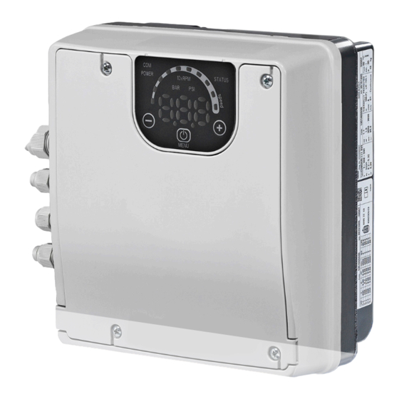
Control panel Figure 16: Control panel Table 10: Description of the control panel Position number Position number Decrease button Increase button START/STOP and menu access button POWER LED Status LED Speed LED bar Communication LED Unit of measure LEDs Display Description of the buttons Table 11: Functions of push buttons Push Button... -
Page 21: Leds Description
LEDs description POWER (power supply) When ON (POWER) the pump is powered and the electronic devices are operational. STATUS Status Pump unit stopped Green Steady Pump unit in operation Flashing green and orange Non-locking alarm with the pump unit in operation Orange steady Non-locking alarm with the pump unit stopped Red steady... - Page 22 The optional communication module is being used. Status RS485 or wireless connection faulty or missing Flashing The unit is exchanging information with the communication module Unit of measurement LED on Measurement active Notes 10xRPM Impeller rotation speed The display shows the speed in 10xRPM Hydraulic head The display shows the value of the head in bar The display shows the value of the head in psi...
-
Page 23: Parameters Menu Visualization
Parameters menu visualization The parameter menu gives the possibility to: • Select all the parameters. • Access Parameter View / Editing. Parameter Description Power On If after switching ON, parameter Menu View is accessed with P23 = ON, P20 flashes: Enter the password to display and change the parameters. - Page 24 Status Parameters Parameter Unit of Description measurement Required value bar/psi/ This parameter shows the SOURCE and the VALUE of the active required value. Visualization cycles between SOURCE and VALUE occur every 3 seconds. SOURCES: • SP (SP): internal required value Setpoint related to the control mode selected.
- Page 25 Power Module °C Temperature of the power module. Temperature This parameter shows the actual current supplied by the frequency Inverter Current converter. This parameter shows the actual estimated input voltage of the Inverter Voltage frequency converter. rpmx10 This parameter shows the actual motor rotational speed. Motor Speed This parameter shows the Control Board software version.
- Page 26 Drive Configuration Parameters Parameter Unit of Description measurement Control mode [ACT, This parameter sets the Control Mode (default value: HCS) HCS, MSE, MSY] ACT: Actuator mode. A single pump maintains a fixed speed at any flow rate. ACT will always try to minimize the difference between the speed setpoint and the actual rotational speed of the motor.
- Page 27 P30 Ramp 3 [1-999] This parameter adjusts the slow acceleration. It determines: • The adjustment speed, in case of small flow rate variations • The constant outgoing pressure. The ramp depends on the system being controlled, and affects the control of the pump in HCS, MSE and MSY modes. Default: 35 s. Adjustment of the slow deceleration time.
- Page 28 Sensor Configuration Parameters No. Parameter Unit of Description measurement Pressure Sensor Unit This parameter sets the unit of measure (BAr, PSI) for the pressure Of Measure [BAR, sensor. PSI] It affect the head view LED parameter. Default: bar. Full scale value for bar/psi This parameter sets the Full Scale value of the 4-20mA pressure pressure Sensor...
- Page 29 RS485 Interface Parameters No. Parameter Unit of Description measurement P50 Communication This parameter selects the specific protocol on the communication protocol [MOD, BAC] port: • NOD (MOD): Modbus RTU • BAC (BAC): BACnet MS/TP. Default: MOD. Communication This parameter sets the desired address for the unit, when protocol - Address connected to an external device, depending on the protocol [1-247]/[0-127]...
-
Page 30: Technical References
Multipump rpmx10 This parameter sets the speed limit below which the first assist Synchronous – pump stops. Speed Limit Default: depending on the type of pump. [P27-P26] Multipump rpmx10 This parameter sets the speed limit for the stop of the next assist Synchronous –... - Page 31 Speed [rpm] Actual speed relative to the 0-10V analogue input voltage value (see Par. 4.3.3, table 8 contacts 7 and 8) P26 (Max RPM set) P27 (Min RPM set) Setpoint Example of Actual Speed related to a specific Vset Voltage value Input Voltage at which the motor goes in Stand By Vin [V] Input Voltage value to control the pump in ACT mode...
-
Page 32: Troubleshooting
Calculation of Effective Required Value in Cascade Serial (MSE): K = number of active pumps Pr = pump priority P02 (Actual Required Value) = P01 (Required Value) + (K – 1) * P58 (Actual Value Increase) – (Pr – 1) * P59 (Actual Value Decrease) Calculation of Effective Required Value in Cascade Synchronous (MSY): K = number of active pumps (K ≥... -
Page 33: Alarm Codes
1. Reset the default parameters using alarm corrupted parameter P68 2. Wait 10 s 3. Restart the pump If the problem continues, contact Flowtech LOW alarm Lack of water Check the water level inside the tank detection (if P48= ALR) -
Page 34: Error Codes
Remedy Internal Internal Stop the pump for 5 minutes and then restart it communication communication lost again; if the problem continues, contact Flowtech error Motor overload High motor current Stop the pump for 5 minutes and then restart it error Current absorbed again;... -
Page 35: Technical Data
Technical Data Table 16: Electrical, Environmental and Installation specifications Drive Model Input Input Frequency (hz) 50/60 ± 2 Main Supply L1 L2 Nominal input voltage 208-240 ±10% 208-240 / 380-460 ±10% 380- ±10% Maximum current See data plate absorbed (AC) in continuous service (S1) PDS Efficiency Class IES2... -
Page 36: Dimensions And Weights
Dimensions and weights... - Page 37 Unit 1 Lock Flight Buildings, Wheatlea Industrial Estate, Wigan, Greater Manchester WN3 6XP United Kingdom 9001 : 2015 REGISTERED Membership No. 700106 Certificate No. 185352020 Copyright © 2020 • All Rights Reserved • Flowtech Water Solutions Limited • Company Number: 05125479 • VAT Number: 836 8024 19...
Need help?
Do you have a question about the 103 and is the answer not in the manual?
Questions and answers