Advertisement
INSTALLATION INSTRUCTIONS
NI 2806
Expansion Bridge for the NI SwitchBlock
This document describes how to install the NI 2806 expansion bridge for the NI SwitchBlock.
Installing the NI 2806 expansion bridge enables you to connect the analog buses of multiple
NI SwitchBlock carriers.
For information about enabling multiple devices to connect to the same analog bus line, refer to
the NI Switches Help.
National Instruments recommends using NI Switch Executive for multicarrier systems. The
NI Switch Executive Help includes information about creating multicarrier virtual devices using
NI Switch Executive.
What You Need to Get Started
To use the expansion bridge, you need the following items:
❑
NI 2806 expansion bridge for the NI SwitchBlock
❑
Two NI PXI-2800 NI SwitchBlock carriers
❑
#1 Phillips screwdriver
Getting Started with the NI 2806 Expansion Bridge for
the NI SwitchBlock
Complete the following steps to install the NI 2806 expansion bridge between
two NI SwitchBlock carriers.
1.
Power off the chassis.
2.
Determine which expansion bridge connectors on each carrier will connect to the expansion
bridge.
When the carriers you want to connect are adjacent to each other in a PXI chassis, the
expansion bridge connectors that face each other will connect to the expansion bridge.
3.
Refer to Figure 1 and unscrew the two screws on the expansion bridge connector covers
determined in step 2 using the #1 Phillips screwdriver.
Advertisement
Table of Contents

Related Manuals for National Instruments 2806


Summary of Contents for National Instruments 2806
- Page 1 NI 2806 Expansion Bridge for the NI SwitchBlock This document describes how to install the NI 2806 expansion bridge for the NI SwitchBlock. Installing the NI 2806 expansion bridge enables you to connect the analog buses of multiple NI SwitchBlock carriers.
- Page 2 Remove the expansion bridge connector covers only from the expansion bridge connectors that will connect to the expansion bridge. Caution You must replace the expansion bridge connector covers if you remove the NI 2806 expansion bridge. NI PXI-2800 Carrier Screws Expansion Bridge Connector Cover Figure 1.
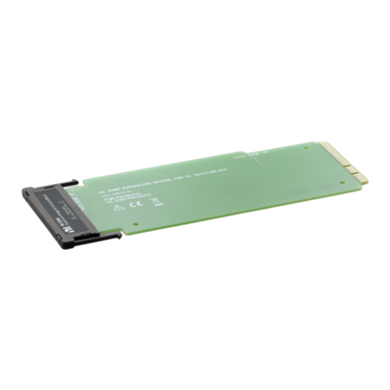
- Page 3 ASSY 150041A-01L FOR PATENTS: NI.COM/PATENTS Figure 2. Correct Orientation of the NI 2806 Expansion Bridge Refer to Figure 3 and insert the NI 2806 expansion bridge between the two carriers until the latches engage. Chassis NI 2806 Expansion Bridge NI PXI-2800 Carriers Latches Figure 3.
- Page 4 Instruments Patents Notice at ni.com/patents. Refer to the Export Compliance Information at ni.com/legal/export-compliance for the National Instruments global trade compliance policy and how to obtain relevant HTS codes, ECCNs, and other import/export data. © 2010–2011 National Instruments Corporation. All rights reserved.
Need help?
Do you have a question about the 2806 and is the answer not in the manual?
Questions and answers