
Related Manuals for StrongLink SL025B

Summary of Contents for StrongLink SL025B
- Page 1 RFID MODULE Mifare Reader / Writer SL025B User Manual Version 3.0 Jan 2018 StrongLink...
-
Page 2: Table Of Contents
StrongLink SL025B CONTENT 1. MAIN FEATURES ................3 2. PINNING INFORMATION ..............4 3. BAUD RATE SETTING .................5 4. COMMUNICATION PROTOCOL ............5 4-1. C ..............5 OMMUNICATION ETTING 4-2. C ..............5 OMMUNICATION ORMAT 4-3. C ................6 OMMAND VERVIEW 4-4. C ..................7 OMMAND 4-4-1. Select Mifare card ................7 4-4-2. -
Page 3: Main Features
StrongLink SL025B 1. MAIN FEATURES • Tags supported: Mifare 1k, Mifare 4k, Mifare UltraLight and NFC NTAG203 • Auto-detecting tag, Built-in antenna • RS232 interface, baud rate 9,600 ~ 115,200 bps • 4.4 ~ 12.0VDC power supply • Work current less than 80mA •... -
Page 4: Pinning Information
StrongLink SL025B 2. PINNING INFORMATION Connector: Würth Elektronik 653 105 131 822 SYMBOL TYPE DESCRIPTION Tag detect signal, RS232 level TagSta Output Logic 0 indicating tag in detection range Logic 1 indicating tag out Output Serial output port Input Serial input port... -
Page 5: Baud Rate Setting
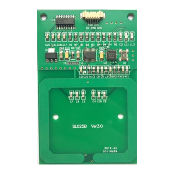
StrongLink SL025B 3. BAUD RATE SETTING Two 820 ohm resistances R6 & R7 are used for setting baud rate as follows sheet Baud rate bps 9,600 19,200 Assembled 57,600 115,200 ( default ) 4. COMMUNICATION PROTOCOL 4-1. Communication Setting The communication protocol is byte oriented. Both sending and receiving bytes are in hexadecimal format. -
Page 6: Command Overview
StrongLink SL025B 4-3. Command Overview Table 3 Command Description 0x01 Select Mifare card 0x02 Login to a sector 0x03 Read a data block 0x04 Write a data block 0x05 Read a value block 0x06 Initialize a value block 0x07 Write master key (key A) -
Page 7: Command List
StrongLink SL025B 4-4. Command List 4-4-1. Select Mifare card 0xBA 0x01 Checksum Response: 0xBD 0x01 Status Type Checksum Status: 0x00: Operation succeed 0x01: No tag 0xF0: Checksum error UID: The uniquely serial number of Mifare card, Type: 0x01: Mifare 1k, 4 byte UID... -
Page 8: Login Sector Via Stored Key
StrongLink SL025B 4-4-4. Login sector via stored key 0xBA 0x13 Sector Type Checksum Sector: Sector need to login, 0x00 – 0x27 Type: Key type (0xAA: KeyA, 0xBB: KeyB) Response: 0xBD 0x13 Status Checksum Status: 0x02: Login succeed 0x03: Login fail... -
Page 9: Initialize A Value Block
StrongLink SL025B 0x01: No tag 0x04: Read fail 0x0D: Not authenticate 0x0E: Not a value block 0xF0: Checksum error Value : Value returned if the operation succeeds, 4 bytes. 4-4-8. Initialize a value block 0xBA 0x06 Block Value Checksum Block: The absolute address of block to be initialized, 1 byte. -
Page 10: Decrement Value
StrongLink SL025B Status: 0x00: Operation succeed 0x01: No tag 0x05: Write fail 0x06: Unable to read after write 0x0D: Not authenticate 0x0E: Not a value block 0xF0: Checksum error Value: The value after increment if the operation succeeds, 4 bytes 4-4-11. -
Page 11: Write A Data Page (Ultralight)
StrongLink SL025B Response: 0xBD 0x10 Status Data Checksum Status: 0x00: Operation succeed 0x01: No tag 0x04: Read fail 0x08: Address overflow 0xF0: Checksum error Data: Block data returned if operation succeeds, 4 bytes. 4-4-14. Write a data Page (UltraLight & NTAG203) - Page 12 StrongLink SL025B Remark In order to support 7 byte UID Mifare class, the firmware of SL025 has been updated to Ver1.2 in Mar 2011. And older firmware version (such as Ver1.0, 1.1) only supports 4 byte UID. Please refer to NXP Customer Letter UID for detailed information of 4 byte &...
- Page 13 Federal Communications Commission (FCC) Interference Statement This equipment has been tested and found to comply with the limits for a Class B digital device, pursuant to Part15 of the FCC Rules. These limits are designed to provide reasonable protection against harmful interference in a residential installation.
- Page 14 In these and circumstance, the OEM integrator will be responsible for re-evaluating. The end product (including the transmitter) and obtaining a separate FCC authorization. The final end product must be labeled in a visible area with the following: “Contains Transmitter Module FCC ID: 2ADI8-SL025B or Contains FCC ID: 2ADI8-SL025B”.
Need help?
Do you have a question about the SL025B and is the answer not in the manual?
Questions and answers