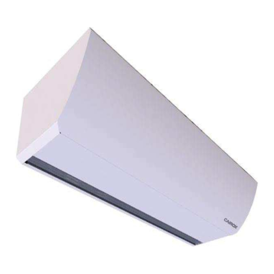
Summary of Contents for Cairox SOLANO W-100
- Page 1 SOLANO DESIGN TECHNICAL DOCUMENTATION / TECHNISCHE DOCUMENTATIE GEBRUIKSAANWIJZING / NOTICE D’UTILISATION / DOKUMENTACJA TECHNICZNA / MŰSZAKI LEÍRÁS...
-
Page 2: Table Of Contents
1. GENERAL INFORMATION ..........................2 DIMENSIONS..............................3 3. TECHNICAL DATA ............................3 4. INSTALATION ..............................4 4.1. RECOMMENDATION OF MONTAGE DISTANCES ................. 4 4.2. MOUNTING USING RODS UNDER THE CEILING .................. 4 4.3. MOUNTING AT WALLS USING BRACKETS ................... 4 4.4. -
Page 3: Dimensions
W-100 N-100 E-100 W-150 N-150 E-150 W-200 N-200 E-200 3x400 / 3x400 / 230 / 50 230 / 50 230 / 50 3x400 / 50 0,36 0,46 0,48 11,5 0,53 0,54 15,5 16,6 22,4 IP-Insulation class 21/F Connecting stub [”] Max. -
Page 4: Instalation
Width of doorway must be equal or lower than width of air curtain outlet (or outlets if air curtains are installed side by side). In case of installation under the ceiling, 4 pcs of M8 rods should be screwed into the hole: -for 20 mm in case of rodsŒ... -
Page 5: Brackets
BRACKETS Brackets S-UB (option) The set of brackets includes two consoles made of flat bar with Ø10 holes and a set of rods with nuts and washers. Is required to fix each bracket to the wall by two screws (min. M8). Installation of each bracket on the unit should also be performed using the supplied M8 rods, as indicated in the figure below. -
Page 6: Control System
CONTROL SYSTEM CONTROL SYSTEM – enables: Connection of the room thermostat*, S-C fan switch, two-* or three-way* valve and S-DS-MEC or S-DS-RMAG door contact*; * not a standard equipment - available as an option In this technical documentation we present the main connection diagrams air curtains SOLANO DESIGN with control S-C. -
Page 7: Connecting Guide
CONNECTING GUIDE To connect the control system and power supply to the SOLANO DESIGN curtain, the front panel must be opened by unscrewing the screws located in the upper parts of the unit. Power and control wires must be routed through rubber passages located in the upper part of the air curtian. -
Page 8: Electric Scheme Solano Design W/N
ELECTRIC SCHEME SOLANO DESIGN W/N Power supply 230V/50Hz (OMY 3x1,0mm Œ Valve with actuator S-V-3 (OMY 3x0,75mm • or S-V-2 (OMY 3x0,75mm A – Exchanger water supply AB – Valve water supply B – Return pipe water supply Door contact S-DS-RMAG / S-DS-MEC (door Ž... -
Page 9: Electric Scheme- Curtain Chaining
ELECTRIC SCHEME- CURTAIN CHAINING Single S-C controller can run with up to 2 air curtains. Larger number of air curtains need to be connected via RX splitter. Power supply Œ Valve with actuator S-V-3 (OMY 3x0,75mm ) or S-V-2 • (OMY 3x0,75mm A –... -
Page 10: Solano Design Control System
SOLANO DESIGN CONTROL SYSTEM Œ Power supply 230V/50Hz; • Connectors for thermostat and fan step switch; Ž Door contact connector; • Valve actuator connector DESIGN-..-W; heaters contactor connector DESIGN-..-E; • BMS system connection; ‘ S-TOUCH connectors; ’ MASTER-SLAVE connectors; “ PT-1000 connectors; LED INDICATORS: G1, G2, G3 –... -
Page 11: Regulation S-Touch - Solano Design W/N Wiring Diagram
Service switch / Servieschakelaar / Switch de service / Przełącznik serwisowy/ Főkapcsoló MASTER mode operating / Werkend in MASTER-modus / Mode MAITRE/ SLAVE mode operating / Werkend in SLAVE-modus /Mode Praca w trybie MASTER/ ESCLAVE/Praca w trybie SLAVE/ ALÁRENDELT FÖLÉRENDELT mód Service / Service / Switch de service / Przełącznik serwisowy/ Főkapcsoló... -
Page 12: 5.7 Regulation S-Touch - Solano Design E Wiring Diagrams
5.7 REGULATION S-TOUCH - SOLANO DESIGN E WIRING DIAGRAMS Œ Power supply 3x400V/50Hz Ž Door contact S-DS-MAG / S-DS-MEC (door closed – contacts opened; door opened – - DESIGN-E-100 (min. 5x2,5 mm (Overcurrent B16) contacts closed) (OMY 2x0,5mm - DESIGN -E-150 (min. 5x4,0 mm •... -
Page 13: Guidelines For Connection With Power Supply
GUIDELINES FOR CONNECTION WITH POWER SUPPLY - Before connecting the power supply check the correctness of connection of the fan motor and the ontrollers These connections should be executed in accordance with their technical documentation. - Before connecting the power supply check whether the mains voltage is in accordance with the voltage on the device data shield. -
Page 14: Cleaning And Conservation
CLEANING AND CONSERVATION Periodically check (min. twice a year) state of contamination of the heat exchanger , electric heaters safety net. Contamination of the air inlet causes a decrease of heating capacity of the unit and the adverse impact on fan operation (causes waving). If cleaning of heat exchanger is needed use listed guidelines: - Disconnect power supply of unit.


Need help?
Do you have a question about the SOLANO W-100 and is the answer not in the manual?
Questions and answers