Huawei LUNA2000-2.0MWH Series User Manual
Smart string ess
Hide thumbs
Also See for LUNA2000-2.0MWH Series:
- User manual (263 pages) ,
- Quick manual (206 pages) ,
- Quick maintenance manual (40 pages)

Related Manuals for Huawei LUNA2000-2.0MWH Series


Summary of Contents for Huawei LUNA2000-2.0MWH Series
- Page 1 LUNA2000-2.0MWH Series Smart String ESS User Manual Issue Date 2022-11-15 HUAWEI TECHNOLOGIES CO., LTD.
- Page 2 Notice The purchased products, services and features are stipulated by the contract made between Huawei and the customer. All or part of the products, services and features described in this document may not be within the purchase scope or the usage scope. Unless otherwise specified in the contract, all statements, information, and recommendations in this document are provided "AS IS"...
-
Page 3: About This Document
LUNA2000-2.0MWH Series Smart String ESS User Manual About This Document About This Document Purpose This document describes the installation, electrical connections, commissioning and troubleshooting of LUNA2000-2.0MWH-1H0, LUNA2000-2.0MWH-2H0, LUNA2000-2.0MWH-1H1 and LUNA2000-2.0MWH-2H1 Smart String Energy Storage Systems (also referred to as ESS). Before installing and operating the ESS, ensure that you are familiar with the features, functions, and safety precautions provided in this document. - Page 4 LUNA2000-2.0MWH Series Smart String ESS User Manual About This Document Change History Changes between document issues are cumulative. The latest document issue contains all updates made in previous issues. Issue 08 (2022-11-15) Updated Appearance. Updated 2.5.1 Battery Cabin. Updated 2.5.2 Control Unit Cabin.
- Page 5 LUNA2000-2.0MWH Series Smart String ESS User Manual About This Document Issue 05 (2022-04-30) Updated 4.3.1 Installing Copper Bars Between Battery Packs. Updated 4.3.2 (Optional) Filling the Fire Cylinder with Extinguishant. Updated 11.2 How to Ensure that the Solenoid Valve Is Not Activated.
- Page 6 LUNA2000-2.0MWH Series Smart String ESS User Manual About This Document Updated 2-Overview. Updated 3.2-Space Requirements. Updated 3.3-Foundation Requirements. Updated 4.2-Installing the ESS. Updated 4.3-Installing Components. Updated 5-Installing Cables. Updated 7.4-Powering On the Distribution Transformer. Updated 7.5-Powering On the ESS. Updated 8-SmartLogger Web-based Deployment.
-
Page 7: Table Of Contents
LUNA2000-2.0MWH Series Smart String ESS User Manual Contents Contents About This Document........................ ii 1 Safety Information........................1 1.1 General Safety..................................1 1.2 Personnel Requirements............................... 4 1.3 Electrical Safety..................................5 1.4 Storage and Installation Environment Requirements....................7 1.5 Loading/Unloading and Transportation Requirements................... 11 1.6 Mechanical Safety.................................12... - Page 8 LUNA2000-2.0MWH Series Smart String ESS User Manual Contents 2.6.3.1 T/H Sensor..................................54 2.6.3.2 Air Conditioner in the Control Unit Cabin......................55 2.6.3.3 Air Conditioner in the Battery Cabin........................56 2.6.3.4 Electrode Water Sensor..............................57 2.6.3.5 Door Status Sensor................................ 58 2.6.3.6 Light....................................59 2.6.4 Fire Suppression System..............................59...
- Page 9 LUNA2000-2.0MWH Series Smart String ESS User Manual Contents 5.1 Preparing Cables................................. 112 5.2 Connecting Socket Circuit Wires........................... 113 5.3 Installing DC Power Cables............................. 120 5.4 Installing AC Input Power Cables (With External Grid Power Supply)............125 5.5 (Optional) Connecting Single-phase AC Input Power Cables (Without External Grid Power Supply).130 5.6 Installing Signal Cables..............................
- Page 10 LUNA2000-2.0MWH Series Smart String ESS User Manual Contents 11.6 What Should I Do If the ESU Cable Connection Detection Abnormal Alarm Is Generated on the WebUI?......................................222 11.7 How Do I Perform a Dielectric Voltage Withstand Test on the AC Side of an ESS?........ 222 12 Technical Data........................
-
Page 11: Safety Information
LUNA2000-2.0MWH Series Smart String ESS User Manual 1 Safety Information Safety Information 1.1 General Safety Statement Before installing, operating, and maintaining the equipment, read this document and observe all the safety instructions on the equipment and in this document. The information provided under the NOTICE, CAUTION, WARNING, and DANGER... - Page 12 LUNA2000-2.0MWH Series Smart String ESS User Manual 1 Safety Information ● Damage due to customer's failure to comply with transportation and installation requirements ● Storage conditions that do not meet the requirements specified in this document ● Damage to the hardware or data of the equipment due to customer's negligence, incorrect operation, or intentional damage ●...
- Page 13 LUNA2000-2.0MWH Series Smart String ESS User Manual 1 Safety Information General Requirements D ANGER Improper operations on high-voltage equipment may cause an electric shock or fire, which could result in death, serious injury, or serious property damage. Comply with the following precautions: ●...
-
Page 14: Personnel Requirements
LUNA2000-2.0MWH Series Smart String ESS User Manual 1 Safety Information CA UTION ● The equipment is equipped with a fire suppression system. Do not start the fire suppression system in non-emergency situations. ● A fire suppression system is equipped. Do not press the extinguishant release button in non-emergency situations. -
Page 15: Electrical Safety
LUNA2000-2.0MWH Series Smart String ESS User Manual 1 Safety Information NO TE For specific qualification requirements, see local laws, regulations, and industry standards. Figure 1-1 Wearing PPE ● Before installing, operating, or maintaining the equipment, remove conductive objects such as watches, bracelets, bangles, rings, and necklaces to prevent electric shock. - Page 16 LUNA2000-2.0MWH Series Smart String ESS User Manual 1 Safety Information ● Select cables that comply with local laws and regulations. ● A fire suppression system is equipped. Do not press the extinguishant release button in non-emergency situations. ● The positions where cables are routed through pipes or holes must be protected to prevent the cables from being damaged by sharp edges or burrs.
-
Page 17: Storage And Installation Environment Requirements
LUNA2000-2.0MWH Series Smart String ESS User Manual 1 Safety Information Before performing maintenance and repair, securely connect the loop to be repaired to the ground loop using a ground cable. NO TICE ● Before connecting a cable, check that the labels on it are correct. - Page 18 LUNA2000-2.0MWH Series Smart String ESS User Manual 1 Safety Information ESS Storage Requirements ● The total storage and transportation time of the ESS or battery packs cannot exceed eight months (starting from delivery). If it exceeds eight months, charge the battery packs and calibrate the SOC to at least 50%. Otherwise, the battery pack performance and service life may be affected.
- Page 19 LUNA2000-2.0MWH Series Smart String ESS User Manual 1 Safety Information Storage Requirements for Fire Suppression Equipment In China: ● Check the backup battery of the extinguishant control panel once a month. If the terminal voltage is lower than the standard voltage, charge the battery immediately.
- Page 20 LUNA2000-2.0MWH Series Smart String ESS User Manual 1 Safety Information ● Take protection and isolation measures for the ESS, such as installing fences, walls, and safety warning signs to prevent personal injury or property damage caused by unauthorized access during operations.
-
Page 21: Loading/Unloading And Transportation Requirements
LUNA2000-2.0MWH Series Smart String ESS User Manual 1 Safety Information ● Stop working at heights in rain and other hazardous situations. After the preceding conditions no longer exist, the safety director and relevant technical personnel must check the involved equipment. Operators can begin working only after obtaining approval. -
Page 22: Mechanical Safety
LUNA2000-2.0MWH Series Smart String ESS User Manual 1 Safety Information International Maritime Dangerous ● Maritime transport must comply with the Goods Code (IMDG Code). International Carriage of Dangerous ● Road transport must comply with the Goods by Road (ADR) or JT/T 617. - Page 23 LUNA2000-2.0MWH Series Smart String ESS User Manual 1 Safety Information Using a Jack ● A hydraulic jack is used to lift the container. Load bearing requirement: 30 t ● To ensure equipment safety, strictly follow the instructions in the manual. Lift the ESS only from one side.
- Page 24 LUNA2000-2.0MWH Series Smart String ESS User Manual 1 Safety Information ● When climbing a ladder, take the following precautions to reduce risks and ensure safety: – Keep your body steady. – Do not climb higher than the fourth rung of the ladder from the top.
-
Page 25: Battery Safety
LUNA2000-2.0MWH Series Smart String ESS User Manual 1 Safety Information ● Wear protective gloves and anti-smashing shoes when manually moving the equipment. ● Do not scratch the equipment surface or damage components or cables when moving the equipment. ● When transporting the equipment using a forklift truck, ensure that the forks are properly positioned so that the equipment does not topple. - Page 26 LUNA2000-2.0MWH Series Smart String ESS User Manual 1 Safety Information Basic Requirements D ANGER ● Do not expose battery packs at high temperatures or around heat-generating sources, such as sunlight, fire sources, transformers, and heaters. Overheating battery packs may cause fires or explosions.
- Page 27 LUNA2000-2.0MWH Series Smart String ESS User Manual 1 Safety Information ● Do not use damaged battery packs (dented on the enclosure or other damage). Damaged battery packs may cause the release of flammable gases. Do not store damaged battery packs near undamaged products.
- Page 28 LUNA2000-2.0MWH Series Smart String ESS User Manual 1 Safety Information Hazard and Toxicity Description D ANGER ● Hazard: Contact between battery pack terminals and other metal objects may cause heat or electrolyte leakage. The electrolyte is flammable. If the electrolyte leaks, move battery packs away from fire sources immediately.
-
Page 29: Maintenance And Replacement
LUNA2000-2.0MWH Series Smart String ESS User Manual 1 Safety Information ● Do not use a dropped battery pack. Contact the Company's service engineers for evaluation. 1.8 Maintenance and Replacement CA UTION Before removing a component from the cabinet, ensure that other components on the cabinet are secure. - Page 30 LUNA2000-2.0MWH Series Smart String ESS User Manual 1 Safety Information Extinguishant Release or Fire D ANGER Suggestions for onsite O&M personnel: 1. In the case of a fire, immediately leave the building or the equipment area, activate the fire alarm, and call emergency services. Notify the professional...
-
Page 31: Overview
LUNA2000-2.0MWH Series Smart String ESS User Manual 2 Overview Overview 2.1 Model Description Product Model This document involves the following product models: ● LUNA2000-2.0MWH-1HX ● LUNA2000-2.0MWH-2HX NO TE [1]: The number corresponding to X is on the nameplate. Figure 2-1 Model number (LUNA2000-2.0MWH-2HX is used as an example) -
Page 32: Label Description
LUNA2000-2.0MWH Series Smart String ESS User Manual 2 Overview Model Identification You can view the product model on the nameplate on the side of the container. Figure 2-2 Position of the nameplate (1) Position of the nameplate 2.2 Label Description... -
Page 33: Functions And Features
2.3 Functions and Features Functions The Smart String ESS LUNA2000-2.0MWH Series (excluding the Smart PCS) can manage charge and discharge of the DC power rectified by the Smart PCS for power grid peak shaving and frequency regulation. Features... -
Page 34: Appearance
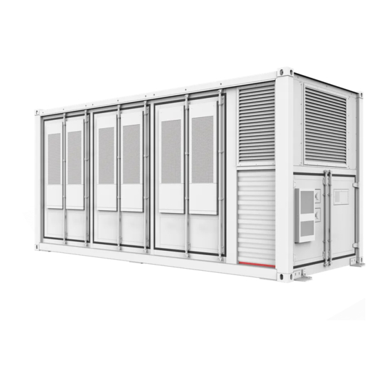
LUNA2000-2.0MWH Series Smart String ESS User Manual 2 Overview ● One controller per rack Each battery rack is connected to a Smart Rack Controller that manages the charge and discharge of the rack independently, improving the available capacity and system availability and supporting the mixed use of old and new batteries. - Page 35 LUNA2000-2.0MWH Series Smart String ESS User Manual 2 Overview Figure 2-3 LUNA2000-2.0MWH-1HX appearance (1) Battery cabin (2) Smart Rack Controller (3) Control unit cabin cabin Figure 2-4 Component position of LUNA2000-2.0MWH-1HX Issue 08 (2022-11-15) Copyright © Huawei Technologies Co., Ltd.
- Page 36 LUNA2000-2.0MWH Series Smart String ESS User Manual 2 Overview LUNA2000-2.0MWH-2HX NO TE The LUNA2000-2.0MWH-2HX models have multiple layouts. The figures use one layout as an example. For details, see the following table. Table 2-3 LUNA2000-2.0MWH-1HX layout Number of DC Number of...
-
Page 37: Ess Composition
LUNA2000-2.0MWH Series Smart String ESS User Manual 2 Overview Figure 2-5 LUNA2000-2.0MWH-2HX appearance 1 (1) Battery cabin (2) Smart Rack Controller (3) Control unit cabin cabin Figure 2-6 Component position 1 of LUNA2000-2.0MWH-2HX 2.5 ESS Composition Issue 08 (2022-11-15) Copyright © Huawei Technologies Co., Ltd. -
Page 38: Battery Cabin
LUNA2000-2.0MWH Series Smart String ESS User Manual 2 Overview 2.5.1 Battery Cabin Figure 2-7 LUNA2000-2.0MWH-1HX battery cabin configurations 1 Figure 2-8 LUNA2000-2.0MWH-2HX battery cabin configurations 1 Table 2-4 Battery cabin configurations 1 Component Configuration Quantity Description Configured Name for an ESS... - Page 39 LUNA2000-2.0MWH Series Smart String ESS User Manual 2 Overview Component Configuration Quantity Description Configured Name for an ESS Battery pack Mandatory The battery pack is a combination of batteries connected in series and output through a pair of positive and negative terminals.
- Page 40 LUNA2000-2.0MWH Series Smart String ESS User Manual 2 Overview Table 2-5 Battery cabin configurations 2 Component Configuration Quantity Description Configured Name for an ESS T/H sensor Mandatory Detects the indoor temperature and humidity in real time. Smoke Mandatory Common photoelectric...
- Page 41 LUNA2000-2.0MWH Series Smart String ESS User Manual 2 Overview Component Configuration Quantity Description Configured Name for an ESS Fuse Mandatory ● LUNA2000- Provides short-circuit 2.0MWH-1 protection. HX: 12 ● LUNA2000- 2.0MWH-2 HX: 6 Black start Optional Used for black start of button the ESS.
-
Page 42: Control Unit Cabin
LUNA2000-2.0MWH Series Smart String ESS User Manual 2 Overview Table 2-6 Battery cabin configurations 3 Component Configuration Quantity Description Configured for Name an ESS Air intake Mandatory Consists of the module labyrinth and air filter foam. Air exhaust Mandatory Consists of the fan... - Page 43 LUNA2000-2.0MWH Series Smart String ESS User Manual 2 Overview Component Configuration Quantity Description Configured Name for an ESS Fire alarm Mandatory Used for audible horn/strobe and visual alarm in the area where an accident occurs. Gas release Mandatory Used for audible...
- Page 44 LUNA2000-2.0MWH Series Smart String ESS User Manual 2 Overview Component Configuration Quantity Description Configured for Name an ESS Mandatory Dissipates heat for conditioner components in the in the control control unit cabin. unit cabin Document Mandatory holder T/H sensor Mandatory...
- Page 45 LUNA2000-2.0MWH Series Smart String ESS User Manual 2 Overview Figure 2-14 LUNA2000-2.0MWH-2HX control unit cabin component configuration Issue 08 (2022-11-15) Copyright © Huawei Technologies Co., Ltd.
- Page 46 LUNA2000-2.0MWH Series Smart String ESS User Manual 2 Overview Figure 2-15 LUNA2000-2.0MWH-2HX control unit cabin component configuration Table 2-9 Control unit cabin component configuration 3 Component Configuration Quantity Description Configured for Name an ESS DC circuit Mandatory ● LUNA2000-2. Provides short-...
- Page 47 LUNA2000-2.0MWH Series Smart String ESS User Manual 2 Overview Component Configuration Quantity Description Configured for Name an ESS SmartModule Optional Converges interfaces, converts protocols, and collects data for devices in the ESS, and expands ports for the CMU. Adapter Mandatory...
-
Page 48: Smart Rack Controller Cabin
LUNA2000-2.0MWH Series Smart String ESS User Manual 2 Overview Component Configuration Quantity Description Configured for Name an ESS Water sensor Mandatory Detects water based on the resistance change between both electrodes. 2.5.3 Smart Rack Controller Cabin Figure 2-16 Configuration of components in the Smart Rack Controller cabin of LUNA2000-2.0MWH-1HX... -
Page 49: Components
LUNA2000-2.0MWH Series Smart String ESS User Manual 2 Overview Figure 2-17 Configuration of components in the Smart Rack Controller cabin of LUNA2000-2.0MWH-2HX Table 2-10 Configuration of components in the Smart Rack Controller cabin Component Configuration Quantity Description Configured for Name... - Page 50 LUNA2000-2.0MWH Series Smart String ESS User Manual 2 Overview Figure 2-18 Appearance Technical Battery Pack Specifications Model ESM51320AS1 ESM-57280AS1 Cell material Lithium iron phosphate Lithium iron phosphate Cell capacity 3.2 V/320 Ah 3.2 V/280 Ah Battery 16S1P 18S1P configuration Rated voltage 51.2 V...
-
Page 51: Smart Rack Controller
LUNA2000-2.0MWH Series Smart String ESS User Manual 2 Overview 2.6.1.2 Smart Rack Controller Figure 2-19 Appearance Table 2-11 Technical specifications of efficiency Technical Specifications Smart Rack Controller Maximum efficiency ≥ 99.0% Table 2-12 Technical specifications of battery side Technical Specifications... -
Page 52: Embedded Power Subrack
LUNA2000-2.0MWH Series Smart String ESS User Manual 2 Overview Table 2-14 General specifications Technical Specifications Smart Rack Controller Parallel mode Two parallel Smart Rack Controllers on the battery side and two on the bus side Overvoltage category Bus side DC II... -
Page 53: Rectifier Module Psu
LUNA2000-2.0MWH Series Smart String ESS User Manual 2 Overview (4) Monitoring module (5) BLVD power distribution (6) Battery wiring ports SMU02C (7) Reserved slot for the (8) User interface module (9) Space for PSUs communications expansion UIM05B1 module CIM02C/NIM01C3 Technical specification... - Page 54 LUNA2000-2.0MWH Series Smart String ESS User Manual 2 Overview Appearance Figure 2-22 Appearance (1) Power indicator (2) Alarm indicator (3) Fault indicator (4) Locking latch (5) Handle Indicators Table 2-15 Indicator description Indicator Color Status Description Power Green Steady on The PSU has an AC input.
-
Page 55: Smu
LUNA2000-2.0MWH Series Smart String ESS User Manual 2 Overview Indicator Color Status Description The PSU is hibernating. Blinking at The communication between the PSU 0.5 Hz and the monitoring module is interrupted. Fault The PSU is normal. indicator Steady on The PSU locks out due to output overvoltage. - Page 56 LUNA2000-2.0MWH Series Smart String ESS User Manual 2 Overview Name Color Status Description Blinking The SMU is running properly and slowly (0.5 communicating with the host properly. Blinking fast The SMU is running properly but fails (4 Hz) to communicate with the host.
- Page 57 LUNA2000-2.0MWH Series Smart String ESS User Manual 2 Overview The LCD supports two-level password management for different users. Table 2-18 Two-level password management Level Operation Permission Password Engineer All permissions except for 000001 changing the administrator password and resetting the...
-
Page 58: Monitoring System
LUNA2000-2.0MWH Series Smart String ESS User Manual 2 Overview Indicator Colo Status Description Blinking The SMU is running properly and slowly (0.5 communicating with the host properly. Blinking fast The SMU is running properly but fails (4 Hz) to communicate with the host. -
Page 59: Cmu
LUNA2000-2.0MWH Series Smart String ESS User Manual 2 Overview 2.6.2.1 CMU Appearance Figure 2-25 Appearance (1) LED indicator (2) SIM card slot (3) Mounting ear (4) Guide rail clamp (5) MBUS port (reserved) (6) GE port (WAN) (7) SFP port... - Page 60 LUNA2000-2.0MWH Series Smart String ESS User Manual 2 Overview Indicators Table 2-20 Indicators Indicator Status Description Running Green off Not powered on indicator Blinking green slowly (on for 1s The communication with (RUN) and then off for 1s) the management system is normal.
-
Page 61: Smartmodule
LUNA2000-2.0MWH Series Smart String ESS User Manual 2 Overview 2.6.2.2 SmartModule Appearance Figure 2-26 Appearance (1) LED indicator (2) Mounting ear (3) Guide rail clamp (4) COM port (5) DI port (6) 12 V output power port (7) AI port... -
Page 62: Input/Output Board (Io Board)
LUNA2000-2.0MWH Series Smart String ESS User Manual 2 Overview Indicators Indicator Status Description Running Green off Not powered on indicator Blinking green slowly (on for The communication with the (RUN) 1s and then off for 1s) CMU is normal. Blinking green fast (on for The communication with the 0.125s and then off for 0.125s) -
Page 63: Environmental Control System
LUNA2000-2.0MWH Series Smart String ESS User Manual 2 Overview Figure 2-27 Position of IO board (1) Position of IO Board Technical Specifications IO Board Model ENF1DETC Operating voltage 220 V AC/12 V DC/24 V DC Operating current ≤ 1 A Operating temperature –30°C to +55°C... -
Page 64: T/H Sensor
LUNA2000-2.0MWH Series Smart String ESS User Manual 2 Overview 2.6.3.1 T/H Sensor Figure 2-28 Appearance NO TE The appearance of the T/H sensor depends on the actual delivery. Table 2-21 T/H sensor technical specifications Technical Specifications T/H sensor Temperature measuring range –20°C to +80°C... -
Page 65: Air Conditioner In The Control Unit Cabin
LUNA2000-2.0MWH Series Smart String ESS User Manual 2 Overview Table 2-22 Pin definitions of an RJ45 connector Description Pin 1 or Pin 4 Pin 2 or Pin 5 Pin 3 Pin 6 Reserved Pin 7 Reserved Pin 8 2.6.3.2 Air Conditioner in the Control Unit Cabin... -
Page 66: Air Conditioner In The Battery Cabin
LUNA2000-2.0MWH Series Smart String ESS User Manual 2 Overview Technical Specifications Air Conditioner in the Control Unit Cabin Heating capacity 1100 W Dimensions (H x W x D) ● 746 mm x 446 mm x 300 mm (without flanges) ● 783 mm x 479 mm x 300 mm (with flanges) -
Page 67: Electrode Water Sensor
LUNA2000-2.0MWH Series Smart String ESS User Manual 2 Overview Technical Specifications Air Conditioner in the Battery Cabin Air conditioner model PC6H Rated voltage 208–230 V AC Rated cooling capacity ● 6350 W (L25/L45) ● 9300 W (L25/L35) Rated heating capacity... -
Page 68: Door Status Sensor
LUNA2000-2.0MWH Series Smart String ESS User Manual 2 Overview Figure 2-32 Appearance Technical Specifications Electrode Water Sensor Operating temperature –40°C to +80°C Storage temperature –40°C to +80°C 2.6.3.5 Door Status Sensor Figure 2-33 Appearance (1) Switch (2) Magnet Technical Door Status Sensor... -
Page 69: Light
LUNA2000-2.0MWH Series Smart String ESS User Manual 2 Overview Technical Door Status Sensor Specifications Switch voltage 100 V DC (Max) Contact withstand 150 V DC (Max) voltage Impedance 0.3 ohms Switch status Steady on Outer material White acrylonitrile butadiene styrene (ABS) engineering plastic 2.6.3.6 Light... -
Page 70: Co Sensor
LUNA2000-2.0MWH Series Smart String ESS User Manual 2 Overview 2.6.4.1 CO Sensor CO sensor detects the concentration of CO in combustible gases. Figure 2-35 Appearance Table 2-23 Technical specifications of the CO sensor Technical Specifications CO Sensor Dimensions (H x W x D) -
Page 71: Air Exhaust Module
LUNA2000-2.0MWH Series Smart String ESS User Manual 2 Overview Table 2-24 Pin definitions of an RJ45 connector Description Pin 1 or Pin 4 Pin 2 or Pin 5 Pin 3 Pin 6 Reserved Pin 7 Reserved Pin 8 V– 2.6.4.2 Air Exhaust Module The air exhaust module is the actuator of the active air exhaust system. -
Page 72: Extinguishant Control Panel
LUNA2000-2.0MWH Series Smart String ESS User Manual 2 Overview Figure 2-38 Appearance (1) Power input ports (2) Fan ports (3) Indicators (4) Communications port 1 (5) Communications port 2 Table 2-25 Indicator description Silkscr Color Status Description Green Steady on Power supply to the board is normal but no program is running. - Page 73 LUNA2000-2.0MWH Series Smart String ESS User Manual 2 Overview Model: K11031M2 Figure 2-39 Appearance Technical Specifications Extinguishant Control Panel Model K11031M2 Dimensions (H x W x D) 385 mm x 310 mm x 90 mm Operating voltage ● 230 V+10%/–15% AC ●...
- Page 74 LUNA2000-2.0MWH Series Smart String ESS User Manual 2 Overview Model: JB-QBL-QM210 Figure 2-40 Appearance Technical Extinguishant Control Panel Specifications Model JB-QBL-QM210 Dimensions (H x 340 mm x 440 mm x 99 mm W x D) Operating voltage ● AC input voltage: 220±20% V AC, 50 Hz ●...
-
Page 75: Fire Cylinder
LUNA2000-2.0MWH Series Smart String ESS User Manual 2 Overview Technical Extinguishant Control Panel Specifications Humidity ≤ 95% RH (non-condensing) IP rating IP30 2.6.4.5 Fire Cylinder Fire cylinder stores fire extinguishant and its components include an electromagnetic valve, pressure gauges, and pipes. -
Page 76: Input/Output Modules
LUNA2000-2.0MWH Series Smart String ESS User Manual 2 Overview Technical Fire Cylinder Specifications Operating 24 V DC 24 V DC 24 V DC voltage Storage 2.5 Mpa 2.5 Mpa 2.5 Mpa pressure (at 20°C) Maximum 4.2 Mpa 4.2 Mpa 4.2 Mpa... - Page 77 LUNA2000-2.0MWH Series Smart String ESS User Manual 2 Overview Figure 2-42 Appearance Figure 2-43 Position of input/output modules (1) Position of input/output modules. Technical Specifications Input/Output modules Model KZJ-956 Cabling mode Non-polarized two-wire system Quiescent current <0.6 mA Operating current <10 mA...
-
Page 78: Fire Signal Transfer Board
LUNA2000-2.0MWH Series Smart String ESS User Manual 2 Overview Technical Specifications Input/Output modules Working status indication ● The indicator blinks about every 12 seconds in the inspection state, and is steady on in the output state. ● The input indicator is steady on in the input state. -
Page 79: Heat Detector
LUNA2000-2.0MWH Series Smart String ESS User Manual 2 Overview Figure 2-45 Position of the fire signal transfer board (1) Position of the fire signal transfer board Technical Specifications Fire Extinguishing Board Model ENF1DETAA Operating voltage 24 V Operating current ≤ 1 A Operating temperature –30°C to +55°C... - Page 80 LUNA2000-2.0MWH Series Smart String ESS User Manual 2 Overview Table 2-26 Indicator description Item Color Status Description Indicators Steady on Enters alarm status Blinking Enters monitoring status Table 2-27 Technical specifications of the heat detector Technical Heat Detector Specifications Configuring model...
-
Page 81: Smoke Detector
LUNA2000-2.0MWH Series Smart String ESS User Manual 2 Overview Technical Heat Detector Specifications IP rating IP54 IP30 2.6.4.9 Smoke Detector The smoke detector can detect the smoke concentration in the environment. Figure 2-47 Appearance Table 2-28 Indicator description Item Color... -
Page 82: Fire Alarm Horn/Strobe
LUNA2000-2.0MWH Series Smart String ESS User Manual 2 Overview Table 2-30 Technical specifications Technical Smoke Detector Specifications Model JTY-GD-930 Dimensions 100 mm diameter x 54 mm height (with mounting base) Operating voltage 24 V Net weight Approx. 82 g Enclosure... - Page 83 LUNA2000-2.0MWH Series Smart String ESS User Manual 2 Overview Model: 958CHL1001 Figure 2-48 Appearance Technical Specifications Fire Alarm Horn/Strobe Model 958CHL1001 Operating voltage Bus 24 V DC Operating current 55 mA MAX @24 V DC Blinking frequency 1 Hz Operating temperature –20°C to +70°C...
- Page 84 LUNA2000-2.0MWH Series Smart String ESS User Manual 2 Overview Model: SG-993 Figure 2-49 Appearance Technical Specifications Fire Alarm Horn/Strobe Model SG-993 Operating voltage 24 V DC Operating current Monitoring status < 1 mA; alarm status < 120 mA Blinking frequency 1 Hz to 1.5 fHz...
-
Page 85: Extinguishant Release Indicator
LUNA2000-2.0MWH Series Smart String ESS User Manual 2 Overview 2.6.4.11 Extinguishant Release Indicator Model: K27102 Figure 2-50 Appearance Technical Specifications Extinguishant Release Indicator Model K27102 Operating voltage –15 V DC to 30 V DC Operating current 140 mA MAX @24 V DC Operating temperature –15°C to +40°C... -
Page 86: Working Principles
LUNA2000-2.0MWH Series Smart String ESS User Manual 2 Overview Technical Specifications Extinguishant Release Indicator Model QM-ZSD-02 Operating voltage 24 V + 24 V DC Operating current ● Bus current in static state: ≤ 500 µA ● When an alarm is generated, bus current ≤... - Page 87 LUNA2000-2.0MWH Series Smart String ESS User Manual 2 Overview Table 2-32 Switch configuration Models Battery Smart Rack DC Circuit Conditio Conditioner Pack Fans Controller Breakers Switches No. Switches Switches No. in the Position Control in the Unit Battery Cabin Cabin...
- Page 88 LUNA2000-2.0MWH Series Smart String ESS User Manual 2 Overview LUNA2000-2.0MWH-1HX Figure 2-52 Battery circuit diagram 1 of the LUNA2000-2.0MWH-1HX Issue 08 (2022-11-15) Copyright © Huawei Technologies Co., Ltd.
- Page 89 LUNA2000-2.0MWH Series Smart String ESS User Manual 2 Overview Figure 2-53 Battery circuit diagram 2 of the LUNA2000-2.0MWH-1HX Issue 08 (2022-11-15) Copyright © Huawei Technologies Co., Ltd.
- Page 90 LUNA2000-2.0MWH Series Smart String ESS User Manual 2 Overview Figure 2-54 Battery circuit diagram 3 of the LUNA2000-2.0MWH-1HX Figure 2-55 Battery circuit diagram 4 of the LUNA2000-2.0MWH-1HX Issue 08 (2022-11-15) Copyright © Huawei Technologies Co., Ltd.
- Page 91 LUNA2000-2.0MWH Series Smart String ESS User Manual 2 Overview LUNA2000-2.0MWH-2HX Figure 2-56 Battery circuit diagram 1 of the LUNA2000-2.0MWH-2HX Issue 08 (2022-11-15) Copyright © Huawei Technologies Co., Ltd.
- Page 92 LUNA2000-2.0MWH Series Smart String ESS User Manual 2 Overview Figure 2-57 Battery circuit diagram 2 of the LUNA2000-2.0MWH-2HX Issue 08 (2022-11-15) Copyright © Huawei Technologies Co., Ltd.
-
Page 93: Working Modes
LUNA2000-2.0MWH Series Smart String ESS User Manual 2 Overview Figure 2-58 Battery circuit diagram 3 of the LUNA2000-2.0MWH-2HX 2.7.2 Working Modes The ESS has six working states: running, hibernation, self-check, fault, offline, and loading. Table 2-33 Working states Working Description... -
Page 94: Typical Application Scenarios
LUNA2000-2.0MWH Series Smart String ESS User Manual 2 Overview Working Description State Fault If a Smart Rack Controller or a battery pack is faulty, the ESS enters the fault state. Offline Smart Rack Controllers are disconnected from the CMU. Loading After the CMU starts, the ESS is waiting for the energy storage units (ESUs) to be connected. - Page 95 LUNA2000-2.0MWH Series Smart String ESS User Manual 2 Overview Figure 2-60 LUNA2000-2.0MWH-2HX networking application (A) Smart ESS (B) DC LV Panel (C) Smart Transformer Station (STS) (D) Step-up transformer (E) Power grid (F) Management system (G) Smart Array Controller (H) Distribution Transformer Issue 08 (2022-11-15) Copyright ©...
-
Page 96: Site Requirements
LUNA2000-2.0MWH Series Smart String ESS User Manual 3 Site Requirements Site Requirements 3.1 Site Selection Requirements NO TICE Standard for the Installation of Site selection must comply with NFPA 855 Stationary Energy Storage Systems and local regulations. The ESS applies only to outdoor scenarios and can only be deployed outdoors. The site selection requirements are as follows: ●... - Page 97 LUNA2000-2.0MWH Series Smart String ESS User Manual 3 Site Requirements NO TE ● When installing, commissioning, and operating the ESS, ensure that at least two gas fire extinguishers are provided near each unit to ensure fire safety. ● Reserve sockets for the water fire suppression system at the ESS site.
-
Page 98: Space Requirements
LUNA2000-2.0MWH Series Smart String ESS User Manual 3 Site Requirements ● Areas prone to flood due to a dam or levee failure ● Protection areas for important water supply sources ● Protection areas for historic relics ● Populated areas, high-rise buildings, and underground buildings ●... -
Page 99: Foundation Requirements
NO TE The foundation layout design should meet the space requirements for ESS installation and O&M. The design institute can contact local Huawei pre-sales engineers to obtain the drawings about the foundation. Before installation, build a concrete platform and trenches on the selected ground. - Page 100 LUNA2000-2.0MWH Series Smart String ESS User Manual 3 Site Requirements Figure 3-1 Diagram of foundation Issue 08 (2022-11-15) Copyright © Huawei Technologies Co., Ltd.
-
Page 101: Installation
LUNA2000-2.0MWH Series Smart String ESS User Manual 4 Installation Installation 4.1 Installation Preparations 4.1.1 Preparing Tools NO TE ● The tools shown in the figures are for reference only. ● The tool table may not list out some tools required onsite. Onsite installation personnel and the customer need to prepare the tools based on site requirements. - Page 102 LUNA2000-2.0MWH Series Smart String ESS User Manual 4 Installation Wire strippers Diagonal pliers Utility knife Flat-head insulated torque screwdriver Cable cutter RJ45 crimping tool Vacuum cleaner Multimeter DC voltage measurement range ≥ 1500 V DC Marker Steel measuring Digital or bubble...
- Page 103 LUNA2000-2.0MWH Series Smart String ESS User Manual 4 Installation Rubber mallet Hammer drill Crane Hoisting rope and lifting eye Drill bit (φ14/φ16/ φ20) Personal Protective Equipment (PPE) Insulated gloves Protective gloves Safety goggles Dust mask Safety helmet Safety shoes Reflective vest...
-
Page 104: Installation Environment Check
LUNA2000-2.0MWH Series Smart String ESS User Manual 4 Installation 4.1.2 Installation Environment Check Check the site requirements one by one, and start installation only after all requirements are met. The Company will not be liable for any consequences in the case that the installation environment does not meet the requirements. -
Page 105: Hoisting The Ess
LUNA2000-2.0MWH Series Smart String ESS User Manual 4 Installation Figure 4-1 Position of corner fittings ----End 4.2.2 Hoisting the ESS Prerequisites ● Before installing the equipment, check the ESS for damage, such as holes and cracks, and check the equipment model. If the appearance is abnormal or the equipment model is incorrect, contact your dealer. - Page 106 LUNA2000-2.0MWH Series Smart String ESS User Manual 4 Installation Stage Precautions Only trained and qualified personnel should perform hoisting operations. Check that hoisting tools are complete and in good condition. Ensure that the hoisting tools are secured to a load-bearing object or wall.
-
Page 107: Opening The Doors Of The Ess
LUNA2000-2.0MWH Series Smart String ESS User Manual 4 Installation NO TICE When hoisting the ESS, ensure that the four corner fittings of the ESS are aligned with the marked mounting positions for corner fittings on the concrete platforms. Figure 4-2 Hoisting the ESS Step 2 Cut open the protective cover using a utility knife and remove the protective cover. - Page 108 LUNA2000-2.0MWH Series Smart String ESS User Manual 4 Installation Figure 4-3 Position of safety lock and TSA approved lock (1) Safety lock (2) TSA approved lock Step 2 Open the door, take the key from the control unit cabin, and use the key to open the safety lock.
-
Page 109: Grounding The Ess
LUNA2000-2.0MWH Series Smart String ESS User Manual 4 Installation NO TE ● At least two persons are required to open the door. ● After the door is opened, secure it using a door strut to prevent the door from moving. - Page 110 LUNA2000-2.0MWH Series Smart String ESS User Manual 4 Installation Table 4-2 Ground cable description Cable Type Cross- Outer Source Sectional Diameter Area Ground cable Single-core 10–32 mm Prepared by 16–95 mm outdoor the customer copper cable and M10, M12 OT/DT...
- Page 111 LUNA2000-2.0MWH Series Smart String ESS User Manual 4 Installation Figure 4-5 Position of the ground cable hole and pagoda connector cutting (1) Ground cable hole NO TE The position for cutting the pagoda connector is for reference only. The actual cable usage may vary.
-
Page 112: Securing The Ess
LUNA2000-2.0MWH Series Smart String ESS User Manual 4 Installation NO TE – Ground lug: Use ground lugs made of hot-dip zinc-coated flat steel sheet with a cross-sectional area of 40 mm x 4 mm, and leave 300 mm of each ground lug out of the concrete platform (same as the height between the foundation and the ground). - Page 113 LUNA2000-2.0MWH Series Smart String ESS User Manual 4 Installation Figure 4-8 Securing the ESS ----End Follow-up Procedure After the ESS is installed, verify the installation to ensure normal use of products and smooth subsequent installation. Table 4-3 Verifying the installation...
-
Page 114: Installing Components
LUNA2000-2.0MWH Series Smart String ESS User Manual 4 Installation NO TE If the doors of the ESS cannot be opened and closed properly, please refer to the first question in chapter 11, 'How do I Level the ESS When Doors Cannot Be Opened or Closed'. - Page 115 LUNA2000-2.0MWH Series Smart String ESS User Manual 4 Installation NO TE ● There are 25 desiccant bags, four bags for each battery rack in the battery cabin and one bag for the control unit cabin. ● After cables are connected, do not remove the desiccants before power-on.
-
Page 116: Optional) Filling The Fire Cylinder With Extinguishant
LUNA2000-2.0MWH Series Smart String ESS User Manual 4 Installation Figure 4-11 Installing copper bars between battery packs Step 4 Close the battery pack cover. Step 5 Close the battery cabin door. ----End 4.3.2 (Optional) Filling the Fire Cylinder with Extinguishant NO TE This step applies only to some models. - Page 117 LUNA2000-2.0MWH Series Smart String ESS User Manual 4 Installation Step 3 Remove the high-pressure elbow from the changeable-diameter joint using a torque wrench. NO TE If there is no changeable-diameter joint, remove the high-pressure elbow directly from the fire cylinder.
- Page 118 LUNA2000-2.0MWH Series Smart String ESS User Manual 4 Installation Ambient Temperature Pressure (Bar) of Pressure (Bar) of (℃) 227M38UFAA SPS020-MS-032B-EN 26.2 26.54 27.4 28.46 28.6 30.38 29.8 32.31 31.0 34.23 32.2 36.15 Note: The actual cylinder pressure should not be lower than 90% of the specified pressure at the corresponding ambient temperature.
-
Page 119: Installing The Battery In The Extinguishant Control Panel
LUNA2000-2.0MWH Series Smart String ESS User Manual 4 Installation Figure 4-13 Installation process diagram ----End 4.3.3 Installing the Battery in the Extinguishant Control Panel Prerequisites NO TICE ● The extinguishant control panel has been configured and commissioned before delivery. Non-professional personnel are prohibited from configuring the extinguishant control panel without permission. - Page 120 LUNA2000-2.0MWH Series Smart String ESS User Manual 4 Installation Figure 4-14 Position of the extinguishant control panel (1) Position of keys (2) Position of the extinguishant control panel Procedure CA UTION Do not damage components in the extinguishant control panel during the installation.
- Page 121 LUNA2000-2.0MWH Series Smart String ESS User Manual 4 Installation Turn off the extinguishant control panel. Take out the key of the extinguishant control panel. NO TE Hand over the key to the responsible personnel for safekeeping. ● Model: K11031M2 Remove the key from above the extinguishant control panel.
-
Page 122: Installing Cables
LUNA2000-2.0MWH Series Smart String ESS User Manual 5 Installing Cables Installing Cables 5.1 Preparing Cables CA UTION Select cables in compliance with local cable standards, especially the electrical specifications and application environment. The key factors include the rated current, cable type, routing method, maximum expected line loss, rated temperature, ambient temperature, thermal resistance, acidity, sedimentation, and environmental protection requirements. -
Page 123: Connecting Socket Circuit Wires
LUNA2000-2.0MWH Series Smart String ESS User Manual 5 Installing Cables Cable Type Conductor Cross- Outer Termin Source Sectional Area Diameter Range Four-core/Five- ● LUNA2000-2.0M 24.6–72 mm Prepared input core outdoor WH-1HX: 35–185 OT/DT by the power copper/copper- termina customer cable clad aluminum/ ●... - Page 124 LUNA2000-2.0MWH Series Smart String ESS User Manual 5 Installing Cables Figure 5-1 Before installing the socket (1) Cable binding position Step 1 Select a 110 V or 220 V socket as required. Step 2 Connect the live wire and neutral wire.
- Page 125 LUNA2000-2.0MWH Series Smart String ESS User Manual 5 Installing Cables Figure 5-3 Connecting live wires and neutral wires (1) 110 V switch installing position ● Installing a 220 V socket – Connect the live wires (corresponding to cables 1757) and neutral wires (corresponding to cables 1760) from the lower end of the terminal block to the socket.
- Page 126 LUNA2000-2.0MWH Series Smart String ESS User Manual 5 Installing Cables Figure 5-4 Routing the ground cables in from the top ● If cables are routed in from the bottom of the socket, connect one end of the cables (1762) to the ground points of the socket and the other end to the reserved ground points on the rear panel.
- Page 127 LUNA2000-2.0MWH Series Smart String ESS User Manual 5 Installing Cables Figure 5-6 Before installing the socket (1) Cable binding position Step 1 Select a 110 V or 220 V socket as required. Step 2 Connect the live wire and neutral wire.
- Page 128 LUNA2000-2.0MWH Series Smart String ESS User Manual 5 Installing Cables Figure 5-8 Connecting the live wire and neutral wire from the lower end of the switch ● Installing a 220 V socket Connect the live wire (corresponding to cable 1756) and neutral wire (corresponding to cable 1759) from the lower end of the switch to positions 1 and 3 of the XT1 terminal block.
- Page 129 LUNA2000-2.0MWH Series Smart String ESS User Manual 5 Installing Cables Figure 5-10 Connecting the live wires and neutral wires from the lower end of the terminal block Step 4 Connecting ground cables: Determine whether the socket ground cables are routed in from the top or bottom.
-
Page 130: Installing Dc Power Cables
LUNA2000-2.0MWH Series Smart String ESS User Manual 5 Installing Cables Figure 5-12 Routing the ground cables in from the bottom ----End 5.3 Installing DC Power Cables Prerequisites ● The ESS is not powered on. ● The DC power cables have been pre-buried according to the specifications. - Page 131 LUNA2000-2.0MWH Series Smart String ESS User Manual 5 Installing Cables Step 2 Remove the baffle plates for the DC power cables. Figure 5-14 Removing the baffle plates for the DC power cables Step 3 Connect the DC power cables. NO TICE ●...
- Page 132 LUNA2000-2.0MWH Series Smart String ESS User Manual 5 Installing Cables Figure 5-15 DC power cable positions at the bottom (1) DC power cable hole (2) AC input power cable or ground cable hole (3) Optical cable or FE communications cable...
- Page 133 LUNA2000-2.0MWH Series Smart String ESS User Manual 5 Installing Cables Figure 5-16 Connect the single-core DC power cables of LUNA2000-2.0MWH-1HX Figure 5-17 Connect the single-core DC power cables of LUNA2000-2.0MWH-2HX (1) Screw assembly (2) Spring washer (3) Large washer (optional)
- Page 134 LUNA2000-2.0MWH Series Smart String ESS User Manual 5 Installing Cables Figure 5-18 Connect the single-core DC power cables of LUNA2000-2.0MWH-1HX Figure 5-19 Connecting two-core DC power cables of LUNA2000-2.0MWH-2HX (1) Screw assembly (2) Spring washer (3) Large washer (optional) (4) Wiring terminals...
-
Page 135: Installing Ac Input Power Cables (With External Grid Power Supply)
LUNA2000-2.0MWH Series Smart String ESS User Manual 5 Installing Cables Step 4 Install the removed cover. ----End 5.4 Installing AC Input Power Cables (With External Grid Power Supply) Prerequisites ● The ESS is not powered on. ● AC input power cables have been pre-buried according to the specifications. - Page 136 LUNA2000-2.0MWH Series Smart String ESS User Manual 5 Installing Cables Figure 5-20 Removing the protective cover Step 2 Remove the baffle plates for the AC input power cables. Figure 5-21 Removing the baffle plates for the AC input power cables Step 3 Connect AC input power cables.
- Page 137 LUNA2000-2.0MWH Series Smart String ESS User Manual 5 Installing Cables NO TICE ● The screw assembly whose model is subject to the delivery should be tightened according to the corresponding standard torque. ● Partially tighten the nuts of the AC input power cables to a torque of 5 N·m when securing the cables.
- Page 138 LUNA2000-2.0MWH Series Smart String ESS User Manual 5 Installing Cables Figure 5-23 Connecting the four-core AC input power cables (excluding the ground cable and including the neutral wire) (1) Screw assembly (2) Spring washer (3) Large washer (optional) (4) Wiring terminals...
- Page 139 LUNA2000-2.0MWH Series Smart String ESS User Manual 5 Installing Cables Figure 5-24 Connecting the five-core AC input power cable (including the ground cable and the neutral wire) (1) Screw assembly (2) Spring washer (3) Large washer (optional) (4) Wiring terminals...
-
Page 140: Installing Signal Cables
LUNA2000-2.0MWH Series Smart String ESS User Manual 5 Installing Cables 5.5 (Optional) Connecting Single-phase AC Input Power Cables (Without External Grid Power Supply) NO TE ● This step applies only to some models. The figure is for reference only. ● If a UPS or other reliable backup power supply is used, perform the following steps to connect single-phase AC input power cables. -
Page 141: Installing Fe Communications Cables
LUNA2000-2.0MWH Series Smart String ESS User Manual 5 Installing Cables 5.6.1 Installing FE Communications Cables Step 1 Remove the protective cover. Figure 5-26 Removing the protective cover Step 2 Remove the baffle plates for the signal cables. Figure 5-27 Removing the baffle plates for the signal cables Step 3 Connect the FE communications cables to the WAN ports on the CMU. - Page 142 LUNA2000-2.0MWH Series Smart String ESS User Manual 5 Installing Cables Figure 5-28 Optical cable positions at the bottom (1) DC power cable hole (2) AC input power cable or ground cable hole (3) Optical cable or network cable hole (4) UPS or RS485 cable hole (reserved)
-
Page 143: Installing Optical Cables
LUNA2000-2.0MWH Series Smart String ESS User Manual 5 Installing Cables ----End 5.6.2 Installing Optical Cables NO TICE Only professionals are allowed to connect optical cables. Figure 5-30 Optical Terminal Box (ATB) interior (1) Fiber spool (2) Cable clip Step 1 Remove the protective cover. - Page 144 LUNA2000-2.0MWH Series Smart String ESS User Manual 5 Installing Cables Figure 5-31 Removing the protective cover Step 2 Remove the baffle plates for the optical cables. Figure 5-32 Removing the baffle plate for the optical cables Step 3 Remove the external mechanical parts from the ATB.
- Page 145 LUNA2000-2.0MWH Series Smart String ESS User Manual 5 Installing Cables Figure 5-33 Removing external mechanical parts Step 4 Remove the optical cable fastener. Figure 5-34 Removing a fastener Step 5 Connect one end of the optical jumper to the fiber adapter.
- Page 146 LUNA2000-2.0MWH Series Smart String ESS User Manual 5 Installing Cables Figure 5-35 Optical cable positions at the bottom (1) DC power cable hole (2) AC input power cable or ground cable hole (3) Optical cable or FE communications cable (4) UPS or RS485 cable hole (reserved)
-
Page 147: Sealing The Cable Holes
LUNA2000-2.0MWH Series Smart String ESS User Manual 5 Installing Cables ----End 5.7 Sealing the Cable Holes After the cables are installed, seal the cable holes using the sealing mud delivered with the equipment. Issue 08 (2022-11-15) Copyright © Huawei Technologies Co., Ltd. -
Page 148: Checking Before Power-On
LUNA2000-2.0MWH Series Smart String ESS User Manual 6 Checking Before Power-On Checking Before Power-On Item Check Item Acceptance Criteria General Equipment ● The equipment is intact and free from rust or paint inspection appearance flake-off. If paint flakes off, repaint the equipment. - Page 149 LUNA2000-2.0MWH Series Smart String ESS User Manual 6 Checking Before Power-On Item Check Item Acceptance Criteria Accessory The number and positions of external accessories installed meet design requirements. Label All labels are correct, clear, and complete. Cleanness The ESS is clean and tidy inside, without any unnecessary cables, cable ends, terminals, or tools.
-
Page 150: Powering On The System
LUNA2000-2.0MWH Series Smart String ESS User Manual 7 Powering On the System Powering On the System 7.1 Installing the PSU Prerequisites WARNING ● Do not put your hands into the PSU slot to avoid electric shock. ● When the PSU is running, a high temperature is generated around the air outlet at the rear. -
Page 151: Installing The Solenoid Valve
LUNA2000-2.0MWH Series Smart String ESS User Manual 7 Powering On the System Figure 7-1 PSU installation position Procedure Step 1 Push the locking latch leftward. Step 2 Pull out the handle. Step 3 Gently push the PSU into its slot along the guide rails. - Page 152 LUNA2000-2.0MWH Series Smart String ESS User Manual 7 Powering On the System NO TE ● Before installing the solenoid valve, ensure that the fire suppression system has been tested and passed the acceptance inspection. ● The appearance of the solenoid valve is for reference only, and that of the actual product may vary.
-
Page 153: Power-On Process
LUNA2000-2.0MWH Series Smart String ESS User Manual 7 Powering On the System Figure 7-3 Installing the Solenoid Valve ----End 7.3 Power-on Process NO TICE The following figure is used only to guide the power-on sequence of the system. Do not use it for onsite cable connections. - Page 154 LUNA2000-2.0MWH Series Smart String ESS User Manual 7 Powering On the System Figure 7-4 Power-on process of LUNA2000-2.0MWH-1HX Figure 7-5 Power-on process of LUNA2000-2.0MWH-2HX Issue 08 (2022-11-15) Copyright © Huawei Technologies Co., Ltd.
- Page 155 LUNA2000-2.0MWH Series Smart String ESS User Manual 7 Powering On the System NO TICE ● Check the equipment before power-on. For details, see the corresponding user manual. ● Before the first power-on, check that cables are correctly connected. ● Incorrect cable connections may cause damage to the STS or the Smart PCS.
-
Page 156: Powering On The Smart Transformer Station (Sts)
DC power cables and AC input power cables in the control unit cabin of the ESS are in good contact. 7.4 Powering On the Smart Transformer Station (STS) ● If a Huawei STS is used, see the corresponding product documents. ● If non-Huawei transformer is used, see the corresponding product documents from the manufacturer. -
Page 157: Powering On The Distribution Transformer
LUNA2000-2.0MWH Series Smart String ESS User Manual 7 Powering On the System 7.6 Powering On the Distribution Transformer CA UTION Before connecting the power supply, ensure that all switches of the Distribution Transformer are turned off. Procedure Step 1 Turn on the SPD switch MCB 6FB7 on the 400 V side of the auxiliary transformer cabinet. -
Page 158: Powering On The Ess
LUNA2000-2.0MWH Series Smart String ESS User Manual 7 Powering On the System 7.7 Powering On the ESS NO TICE ● Before turning on the switches in the secondary devices of the ESS, check that the AC voltage of the auxiliary power supply and bus voltage are within the normal ranges. - Page 159 LUNA2000-2.0MWH Series Smart String ESS User Manual 7 Powering On the System Procedure Figure 7-6 Switches in the Control Unit Cabin of LUNA2000-2.0MWH-1HX (1) AC power switch of (2) Extinguishant (3) DC input switch, (4) Battery pack fan the air conditioner...
- Page 160 LUNA2000-2.0MWH Series Smart String ESS User Manual 7 Powering On the System Figure 7-7 Switches in the Control Unit Cabin of LUNA2000-2.0MWH-1HX (1) AC power (2) Extinguishant (3) PSU AC input (4) Battery pack switch of the air control panel...
- Page 161 LUNA2000-2.0MWH Series Smart String ESS User Manual 7 Powering On the System Figure 7-8 Positions of the DC circuit breakers of battery racks in the battery cabin (1) Positions of the DC circuit breakers of battery racks in the battery cabin...
- Page 162 LUNA2000-2.0MWH Series Smart String ESS User Manual 7 Powering On the System Table 7-1 Switch configuration Models Battery Pack Smart Rack Conditioner Conditioner Fans Controller Position in Switches No. Switches No. Switches No. the Battery Cabin LUNA2000-2. 1/2/4/5/7/8/1 3FCB1, 3FCB2, 7FCB7–...
- Page 163 LUNA2000-2.0MWH Series Smart String ESS User Manual 7 Powering On the System Figure 7-9 Position of the power switch in the extinguishant control panel (1) Position of the right power switch in the (2) Position of the left power switch in the...
-
Page 164: Optional) Powering On The Battery Side Of The Dc Lv Panel
LUNA2000-2.0MWH Series Smart String ESS User Manual 7 Powering On the System Models Air Conditioner DC Circuit Breakers No. in Position in the Battery the Control Unit Cabin Cabin LUNA2000-2.0MWH-2 1/4/7/10 1Q2–6Q2 NO TE The status of DC switches in the control unit cabin is subject to the actual number of PCSs connected. - Page 165 LUNA2000-2.0MWH Series Smart String ESS User Manual 7 Powering On the System Procedure Step 1 Turn on the AC switch between the Smart PCS and the power grid. Step 2 Turn on the DC switches between the Smart PCS and the DC LV Panel busbar.
- Page 166 LUNA2000-2.0MWH Series Smart String ESS User Manual 7 Powering On the System Category Indicator Description Status Blinking red An environmental fault occurs on the AC side. fast The AC side is not connected to the power grid. Communication Blinking The device receives data through the northbound FE...
-
Page 167: Smartlogger Web-Based Deployment
LUNA2000-2.0MWH Series Smart String ESS User Manual 8 SmartLogger Web-based Deployment SmartLogger Web-based Deployment Prerequisites The commissioning equipment is available onsite. The system is powered on and alarms are cleared. All devices onsite have been commissioned. Before the deployment, wait until the air conditioner adjusts the temperature inside the cabinet and the temperature of batteries to the specified temperature range (5°C to 45°C). - Page 168 LUNA2000-2.0MWH Series Smart String ESS User Manual 8 SmartLogger Web-based Deployment Connected Item SmartLogger Example PC Port Default Value Setting Default gateway 192.168.8.1 192.168.8.1 WAN port IP address 192.168.0.10 192.168.0.11 Subnet mask 255.255.255.0 255.255.255.0 Default gateway 192.168.0.1 192.168.0.1 NO TE ●...
- Page 169 LUNA2000-2.0MWH Series Smart String ESS User Manual 8 SmartLogger Web-based Deployment Figure 8-1 LAN settings Click OK. Step 4 Log in to the SmartLogger WebUI. In the address box of a browser, enter https://XX.XX.XX.XX (XX.XX.XX.XX is the IP address of the SmartLogger) and press Enter. The login page is displayed. If you log in to the WebUI for the first time, a security risk warning is displayed.
-
Page 170: Commissioning Using Deployment Wizard
– Protect the password by changing it periodically, and keep it secure. If you lose the password, the device must be restored to its factory settings. Huawei will not be held liable for any losses resulting from improper password management. - Page 171 Figure 8-4 Using the wireless network (4G/3G/2G) for communication Figure 8-5 Using the ETH interface for communication After Huawei devices are connected, click Search for Device to check cable connections, identify the topology, and rectify alarms. Issue 08 (2022-11-15)
- Page 172 LUNA2000-2.0MWH Series Smart String ESS User Manual 8 SmartLogger Web-based Deployment Figure 8-6 Cable connection detection NO TE – During the process of Search for Device, do not perform upgrade operations (such as upgrading through the app, network management system, or WebUI).
- Page 173 LUNA2000-2.0MWH Series Smart String ESS User Manual 8 SmartLogger Web-based Deployment Figure 8-7 Parameter settings after device search Parameter Description Running under Grid You need to set this parameter only for the PCS, connection state but not the SUN2000. – In the on-grid scenario, set this parameter to On-grid(PQ).
- Page 174 LUNA2000-2.0MWH Series Smart String ESS User Manual 8 SmartLogger Web-based Deployment Figure 8-8 Setting power meter parameters Connect to the EMI. Figure 8-9 Setting EMI parameters Click Settings > Battery control to set the battery working mode. Figure 8-10 Working modes...
- Page 175 LUNA2000-2.0MWH Series Smart String ESS User Manual 8 SmartLogger Web-based Deployment Working Mode Description Maximum self- – This mode applies to areas where the consumption electricity price is high, or areas where the FIT subsidy is low or unavailable. – Excess PV energy is stored in batteries. When...
- Page 176 LUNA2000-2.0MWH Series Smart String ESS User Manual 8 SmartLogger Web-based Deployment Working Mode Description Charge/Discharge based – This mode applies to scheduling scenarios in on grid dispatch ground-mounted plants. – In scheduled discharge, the AC output aims to reach the target value of the scheduled active power: PV power supply is prioritized.
- Page 177 LUNA2000-2.0MWH Series Smart String ESS User Manual 8 SmartLogger Web-based Deployment Parameter Description ▪ Automatic SOC The default value is Disable. calibration ▪ If an ESS is required to automatically calibrate the SOC precision, set this parameter to Enable. During automatic SOC calibration, the SOC of each ESR is charged to 99% or higher in turn.
-
Page 178: Optional) System Setup
LUNA2000-2.0MWH Series Smart String ESS User Manual 8 SmartLogger Web-based Deployment Figure 8-14 Third-party device 10. Complete the configuration. NO TICE SmartLogger V300R023C00 and later versions support the Array startup/ shutdown command. Set Array startup/shutdown based on the site requirements. -
Page 179: Check Alarms
LUNA2000-2.0MWH Series Smart String ESS User Manual 8 SmartLogger Web-based Deployment Procedure Step 1 Choose Maintenance > Connect Device on the SmartLogger WebUI. Step 2 Click in the upper right corner to start devices in batches. Figure 8-15 System startup ----End 8.4 Check Alarms... - Page 180 LUNA2000-2.0MWH Series Smart String ESS User Manual 8 SmartLogger Web-based Deployment Figure 8-17 Position of Electrode Water Sensor in Control Unit Cabin After the alarm is cleared, choose Monitoring > Running Param. > Fire suppression > Starting up on the SmartLogger WebUI.
-
Page 181: Powering Off The System
LUNA2000-2.0MWH Series Smart String ESS User Manual 9 Powering Off the System Powering Off the System 9.1 Delivering a Shutdown Command on the SmartLogger Prerequisites The system has connected to the grid and is running properly. Procedure Step 1 Log in to the SmartLogger WebUI, choose Maintenance > Connect Device, and click to shut down the Smart PCS and Smart Rack Controller. -
Page 182: Power-Off Process
LUNA2000-2.0MWH Series Smart String ESS User Manual 9 Powering Off the System 9.2 Power-off Process Figure 9-2 Power-off process of LUNA2000-2.0MWH-1HX Figure 9-3 Power-off process of LUNA2000-2.0MWH-2HX Issue 08 (2022-11-15) Copyright © Huawei Technologies Co., Ltd. -
Page 183: Powering Off The Smart Pcs
LUNA2000-2.0MWH Series Smart String ESS User Manual 9 Powering Off the System NO TE Before powering off the system, shut down the entire system on the SmartLogger WebUI, including the Smart PCS and the Smart Rack Controller. Proced Item Remarks... -
Page 184: Optional) Powering Off The Battery Side Of The Dc Lv Panel
LUNA2000-2.0MWH Series Smart String ESS User Manual 9 Powering Off the System 9.4 (Optional) Powering Off the Battery Side of the DC LV Panel Step 1 Turn off the switches on the battery side of the DC LV Panel. ----End 9.5 Powering Off the ESS... -
Page 185: Powering Off The Distribution Transformer
LUNA2000-2.0MWH Series Smart String ESS User Manual 9 Powering Off the System Step 2 Switch off DC output circuit breakers of the ESS. Step 3 Switch off all circuit breakers of the ESS power distribution system. Switch off the AC power circuit breakers of the air conditioner in sequence. -
Page 186: Alarm Reference
LUNA2000-2.0MWH Series Smart String ESS User Manual 10 Alarm Reference Alarm Reference Alarm severities are defined as follows: ● Major alarm: The device is faulty or the external environment is abnormal. As a result, the output power decreases or the device stops feeding to the grid. - Page 187 LUNA2000-2.0MWH Series Smart String ESS User Manual 10 Alarm Reference Alarm Alarm Severity Possible Cause Suggestion Name 3802 Fire Alarm Major Cause ID = 1 1. Remotely monitor the system for 30 minutes to check whether other Smoke or overheating is...
- Page 188 LUNA2000-2.0MWH Series Smart String ESS User Manual 10 Alarm Reference Alarm Alarm Severity Possible Cause Suggestion Name 3803 Fire Major Cause ID = 1 1. Troubleshoot faults based on the Suppressio instructions in the fire suppression Sensor or controller fault n System system user manual.
- Page 189 LUNA2000-2.0MWH Series Smart String ESS User Manual 10 Alarm Reference Alarm Alarm Severity Possible Cause Suggestion Name 3809 Major Cause ID = 1–13 1. Shut down the system at a Condition proper time and take safety 1. The fan cable of measures.
- Page 190 LUNA2000-2.0MWH Series Smart String ESS User Manual 10 Alarm Reference Alarm Alarm Severity Possible Cause Suggestion Name 3813 Major Cause ID = 1–13 1. Measure the voltage of the air Condition conditioner wiring terminal. If the 1. The auxiliary power...
- Page 191 LUNA2000-2.0MWH Series Smart String ESS User Manual 10 Alarm Reference Alarm Alarm Severity Possible Cause Suggestion Name 3817 Minor Cause ID = 1–13 1. Shut down the system at a Condition proper time and take safety 1. The cable of [HVAC- measures.
- Page 192 LUNA2000-2.0MWH Series Smart String ESS User Manual 10 Alarm Reference Alarm Alarm Severity Possible Cause Suggestion Name 3821 Major Cause ID = 1–13 1. Check the voltage of the input Condition power supply. If the voltage is too 1. The input voltage of...
- Page 193 LUNA2000-2.0MWH Series Smart String ESS User Manual 10 Alarm Reference Alarm Alarm Severity Possible Cause Suggestion Name 3826 Combustib Major Cause ID = 1 1. Remotely monitor the system for le Gas 30 minutes to check whether other 1. The safety valve of...
- Page 194 LUNA2000-2.0MWH Series Smart String ESS User Manual 10 Alarm Reference Alarm Alarm Severity Possible Cause Suggestion Name Cause ID = 3 1. Check whether the air conditioners in the control unit The ambient cabin are faulty. temperature of the control unit cabin is too 2.
- Page 195 LUNA2000-2.0MWH Series Smart String ESS User Manual 10 Alarm Reference Alarm Alarm Severity Possible Cause Suggestion Name Malfuncti Cause ID = 2 The air conditioners in the control unit cabin are faulty. 3833 Rectifier Major Cause ID = 1–6 1. Replace the rectifier [NUMBER].
- Page 196 LUNA2000-2.0MWH Series Smart String ESS User Manual 10 Alarm Reference Alarm Alarm Severity Possible Cause Suggestion Name 3838 Minor Cause ID = 1–5 1. Check whether the Sensor communication cable is correctly T/H sensor Communic connected to the device. If not, communication failed.
- Page 197 LUNA2000-2.0MWH Series Smart String ESS User Manual 10 Alarm Reference Alarm Alarm Severity Possible Cause Suggestion Name 3845 SmartMod Minor Cause ID = 1 1. Check whether the communication cable is correctly SmartModule Communic connected to the device. If not, communication failed.
- Page 198 LUNA2000-2.0MWH Series Smart String ESS User Manual 10 Alarm Reference Alarm Alarm Severity Possible Cause Suggestion Name 3851 Exhaust Major Cause ID = 1–12 1. Check whether the cable to the Fan Fault exhaust fan is loose. If yes, The exhaust fan is reconnect the cable.
- Page 199 LUNA2000-2.0MWH Series Smart String ESS User Manual 10 Alarm Reference Alarm Alarm Severity Possible Cause Suggestion Name 3857 Memory Minor Cause ID = 1 Contact your technical support. Exception 1. The storage space is insufficient. 2. The memory is faulty.
- Page 200 LUNA2000-2.0MWH Series Smart String ESS User Manual 10 Alarm Reference Table 10-2 PSU indicator status and troubleshooting Indicator Color Status Description Suggestion Power Green Steady on The PSU has Normal. indicator an AC input. The PSU has Check no AC input.
- Page 201 LUNA2000-2.0MWH Series Smart String ESS User Manual 10 Alarm Reference Indicator Color Status Description Suggestion AC input Check the overvoltage power grid voltage. undervoltage protection is triggered. The PSU is Normal. hibernating. Blinking at Replace the 0.5 Hz communicati PSU or...
- Page 202 LUNA2000-2.0MWH Series Smart String ESS User Manual 10 Alarm Reference Table 10-3 ESC/BCU common alarms and troubleshooting measures Alarm Alarm Severity Possible Cause Suggestion Name 3013 Battery Major Cause ID = 1 1. Determine the positions of the Pack input and output circuit breakers...
- Page 203 LUNA2000-2.0MWH Series Smart String ESS User Manual 10 Alarm Reference Alarm Alarm Severity Possible Cause Suggestion Name 3016 Battery Major Cause ID = 1–3 1. Determine the positions of the Side input and output circuit breakers The batteries are Undervolt...
- Page 204 LUNA2000-2.0MWH Series Smart String ESS User Manual 10 Alarm Reference Alarm Alarm Severity Possible Cause Suggestion Name 3017 Battery Major Cause ID = 1–3 1. Locate the input and output Side Short circuit breakers associated with The battery cable is Circuit on [ESC-No].
- Page 205 LUNA2000-2.0MWH Series Smart String ESS User Manual 10 Alarm Reference Alarm Alarm Severity Possible Cause Suggestion Name 3019 Bus Side Major Cause ID = 1–3 1. Locate the input and output Overvolta circuit breakers associated with The bus cable is not ge on [ESC-No].
- Page 206 LUNA2000-2.0MWH Series Smart String ESS User Manual 10 Alarm Reference Alarm Alarm Severity Possible Cause Suggestion Name 3021 Insulation Major Cause ID = 1–3 1. Locate the input and output Resistance circuit breakers associated with 1. The battery is of Rack [ESC-No].
- Page 207 LUNA2000-2.0MWH Series Smart String ESS User Manual 10 Alarm Reference Alarm Alarm Severity Possible Cause Suggestion Name 3023 Battery Major Cause ID = 1–3 1. Locate the input and output Terminal circuit breakers associated with The battery terminal is Overtemp [ESC-No].
- Page 208 LUNA2000-2.0MWH Series Smart String ESS User Manual 10 Alarm Reference Alarm Alarm Severity Possible Cause Suggestion Name 3024 Major Cause ID = 1–3 1. Determine the positions of the Terminal input and output circuit breakers The bus terminal is Overtemp...
- Page 209 LUNA2000-2.0MWH Series Smart String ESS User Manual 10 Alarm Reference Alarm Alarm Severity Possible Cause Suggestion Name 3033 Communi Major Cause ID = 1 1. Locate the input and output cation circuit breakers associated with The internal Failure on [ESC-No].
- Page 210 LUNA2000-2.0MWH Series Smart String ESS User Manual 10 Alarm Reference Alarm Alarm Severity Possible Cause Suggestion Name 3034 Rack Major Cause ID = 1 If the system is in the array topology Controller identification process, wait until the The cable connection...
- Page 211 LUNA2000-2.0MWH Series Smart String ESS User Manual 10 Alarm Reference Alarm Alarm Severity Possible Cause Suggestion Name 3035 Battery Major Cause ID = 1 1. Locate the input and output Pack circuit breakers associated with 1. The actual number Positions [ESC-No].
- Page 212 LUNA2000-2.0MWH Series Smart String ESS User Manual 10 Alarm Reference Alarm Alarm Severity Possible Cause Suggestion Name 3040 Incorrect Major Cause ID = 1 If the system is in the array topology identification process, wait until the The output buses are...
- Page 213 LUNA2000-2.0MWH Series Smart String ESS User Manual 10 Alarm Reference Alarm Alarm Severity Possible Cause Suggestion Name 3042 Rapid Major Cause ID = 1 If the system is in the array topology Shutdown identification process, wait until the The rapid shutdown...
- Page 214 LUNA2000-2.0MWH Series Smart String ESS User Manual 10 Alarm Reference Alarm Alarm Severity Possible Cause Suggestion Name Cause ID = 2 If the system is in the array topology identification process, wait until the The rapid shutdown process is complete or exit the cabling in the battery process.
- Page 215 LUNA2000-2.0MWH Series Smart String ESS User Manual 10 Alarm Reference Alarm Alarm Severity Possible Cause Suggestion Name 3052 External Major Cause ID = 1 1. Locate the input and output circuit breakers associated with 1. The DC circuit Auxiliary [ESC-No].
- Page 216 LUNA2000-2.0MWH Series Smart String ESS User Manual 10 Alarm Reference Alarm Alarm Severity Possible Cause Suggestion Name 3054 Rack Warning Cause ID = 1, 2 1. Locate the input and output Controller circuit breakers associated with The NTC is short- Temperat [ESC-No].
- Page 217 LUNA2000-2.0MWH Series Smart String ESS User Manual 10 Alarm Reference Alarm Alarm Severity Possible Cause Suggestion Name 3059 Communi Major Cause ID = 1 1. Check whether the CMU status cation indicator on the WebUI indicates 1. The Interrupti that the CMU is offline. If yes, check...
- Page 218 LUNA2000-2.0MWH Series Smart String ESS User Manual 10 Alarm Reference Table 10-4 BMU common alarms and troubleshooting measures Alarm Alarm Severity Possible Cause Suggestion Name 3027 Battery Major Cause ID = 1–20 1. The 3027-1 alarm (cell voltage Pack sampling fault) does not affect...
- Page 219 LUNA2000-2.0MWH Series Smart String ESS User Manual 10 Alarm Reference Alarm Alarm Severity Possible Cause Suggestion Name 3029 Battery Major Cause ID = 1, 2 1. Determine the positions of the Pack input and output circuit breakers The battery pack has...
- Page 220 LUNA2000-2.0MWH Series Smart String ESS User Manual 10 Alarm Reference Alarm Alarm Severity Possible Cause Suggestion Name 3030 Battery Major Cause ID = 1 1. Determine the positions of the Module input and output circuit breakers 1. The fan is short-...
- Page 221 LUNA2000-2.0MWH Series Smart String ESS User Manual 10 Alarm Reference Alarm Alarm Severity Possible Cause Suggestion Name 3032 Battery Major Cause ID = 1, 2 1. The 3032-1 alarm (battery pack Pack overvoltage protection) does not The voltage of the...
- Page 222 LUNA2000-2.0MWH Series Smart String ESS User Manual 10 Alarm Reference Alarm Alarm Severity Possible Cause Suggestion Name 3037 Overtemp Minor Cause ID = 1–3 1. Determine the position of [ESR- erature on CabinetNo ESM-SlotNo] and the 1. The installation Optimizati...
- Page 223 LUNA2000-2.0MWH Series Smart String ESS User Manual 10 Alarm Reference Alarm Alarm Severity Possible Cause Suggestion Name 3039 Battery Major Cause ID = 1, 2 1. The versions of optimization Pack units in [ESR-CabinetNo ESM- The update failed. Optimizati SlotNo] do not match. Please on Unit update.
- Page 224 LUNA2000-2.0MWH Series Smart String ESS User Manual 10 Alarm Reference Alarm Alarm Severity Possible Cause Suggestion Name 3043 Battery Warning Cause ID = 2 1. Determine the position of [ESR- Module CabinetNo ESM-SlotNo] and the The battery module SOH Low positions of the input and output SOH is too low.
- Page 225 LUNA2000-2.0MWH Series Smart String ESS User Manual 10 Alarm Reference Alarm Alarm Severity Possible Cause Suggestion Name 3045 Battery Major Cause ID = 1, 2 1. Determine the positions of the Pack input and output circuit breakers 1. The installation...
- Page 226 LUNA2000-2.0MWH Series Smart String ESS User Manual 10 Alarm Reference Alarm Alarm Severity Possible Cause Suggestion Name 3046 Battery Major Cause ID = 1, 2 1. The 3046-1 alarm (low Pack temperature protection during The ambient Temperatu battery charge) does not affect...
- Page 227 LUNA2000-2.0MWH Series Smart String ESS User Manual 10 Alarm Reference Alarm Alarm Severity Possible Cause Suggestion Name Cause ID = 4 1. Determine the positions of the input and output circuit breakers 1. The voltage of the of the ESC corresponding to battery pack or its [ESR-CabinetNo ESM-SlotNo].
-
Page 228: Faq
LUNA2000-2.0MWH Series Smart String ESS User Manual 11 FAQ 11.1 (Optional) How to Level the ESS When Doors Cannot Be Opened or Closed NO TE This procedure applies only to some models. Step 1 Use a jack to support the ESS. -
Page 229: How To Ensure That The Solenoid Valve Is Not Activated
LUNA2000-2.0MWH Series Smart String ESS User Manual 11 FAQ Figure 11-1 The Upper Part of the Lock Tongue Interferes With the Upper Surface of the Lock Base (1) Position of leveling washers Scenario 2: The Lower Part of the Lock Tongue Interferes With the Lower Surface of the Lock Base Use leveling washers to raise ESS by 5–10 mm on the foundation under the lock... -
Page 230: How To Connect The Ess To The Smart Pv Management System
LUNA2000-2.0MWH Series Smart String ESS User Manual 11 FAQ Insert the reset device into the solenoid valve to reset the ejector pin. After resetting, remove the solenoid valve reset device. ----End 11.3 How to Connect the ESS to the Smart PV... -
Page 231: Why Does The Psu Not Start After The Water And Fire Alarms Are Cleared
LUNA2000-2.0MWH Series Smart String ESS User Manual 11 FAQ Step 3 Perform the next step as prompted. ----End 11.5 Why Does the PSU Not Start After the Water and Fire Alarms Are Cleared Step 1 Choose Monitoring > Running Param > Fire suppression > Starting up on the SmartLogger WebUI. -
Page 232: What Should I Do If The Esu Cable Connection Detection Abnormal Alarm Is Generated On The Webui
LUNA2000-2.0MWH Series Smart String ESS User Manual 11 FAQ 11.6 What Should I Do If the ESU Cable Connection Detection Abnormal Alarm Is Generated on the WebUI? Step 1 Press the reset button ( ) in the upper right corner of the ESU screen. The ESU restarts cable connection detection. - Page 233 LUNA2000-2.0MWH Series Smart String ESS User Manual 11 FAQ Figure 11-5 2U subrack positions Test Instrument Withstand voltage tester Test Items and Criteria Test Item Procedure Criteria Withstand 1. Short-circuit L1, L2, L3, and ● The leakage current voltage of...
- Page 234 LUNA2000-2.0MWH Series Smart String ESS User Manual 11 FAQ Test Item Procedure Criteria Main ground 1. Short-circuit L1, L2, L3, and ● The test voltage is 1 insulation resistance 2. Select the insulation ● The stable insulation after L1, L2,...
-
Page 235: Technical Data
LUNA2000-2.0MWH Series Smart String ESS User Manual 12 Technical Data Technical Data Table 12-1 Technical Data Technical LUNA2000-2. LUNA2000-2.0 LUNA2000-2. LUNA2000-2.0 Specificat 0MWH-1H0 MWH-2H0 0MWH-1H1 MWH-2H1 ions (320 Ah (320 Ah (280 Ah (280 Ah battery cell) battery cell) battery cell) - Page 236 LUNA2000-2.0MWH Series Smart String ESS User Manual 12 Technical Data Technical LUNA2000-2. LUNA2000-2.0 LUNA2000-2. LUNA2000-2.0 Specificat 0MWH-1H0 MWH-2H0 0MWH-1H1 MWH-2H1 ions (320 Ah (320 Ah (280 Ah (280 Ah battery cell) battery cell) battery cell) battery cell) Rated 1075.2 V 1075.2 V...
- Page 237 LUNA2000-2.0MWH Series Smart String ESS User Manual 12 Technical Data Technical LUNA2000-2. LUNA2000-2.0 LUNA2000-2. LUNA2000-2.0 Specificat 0MWH-1H0 MWH-2H0 0MWH-1H1 MWH-2H1 ions (320 Ah (320 Ah (280 Ah (280 Ah battery cell) battery cell) battery cell) battery cell) Rack Module-level Module-level...
- Page 238 LUNA2000-2.0MWH Series Smart String ESS User Manual 12 Technical Data Technical LUNA2000-2. LUNA2000-2.0 LUNA2000-2. LUNA2000-2.0 Specificat 0MWH-1H0 MWH-2H0 0MWH-1H1 MWH-2H1 ions (320 Ah (320 Ah (280 Ah (280 Ah battery cell) battery cell) battery cell) battery cell) Number 8 or 6...
-
Page 239: A Operations On The Cmu Webui
LUNA2000-2.0MWH Series Smart String ESS User Manual A Operations on the CMU WebUI Operations on the CMU WebUI A.1 CMU WebUI Operations A.1.1 Introduction to WebUI NO TICE ● The web software version corresponding to the WebUI screenshots in this document is FusionSolar V800R021C10. -
Page 240: Icon Description
LUNA2000-2.0MWH Series Smart String ESS User Manual A Operations on the CMU WebUI Function Description First-level menu Choose the corresponding first-level menu before you perform any operation over the WebUI. Second-level Under the first-level menu, choose the device to be queried or menu the parameter to be set under the second-level menu. -
Page 241: Webui Menus
LUNA2000-2.0MWH Series Smart String ESS User Manual A Operations on the CMU WebUI Icon Description Icon Description ● The device is in The CMU is in Disconnection Loading state. state. ● When the device is in Disconnection state, its parameters cannot be set. -
Page 242: Maintenance Operations
LUNA2000-2.0MWH Series Smart String ESS User Manual A Operations on the CMU WebUI Main Menu Second-Level Menu Third-Level Function Menu Settings User parameters Date&Time Sets the date and time. Comm. Param. Wireless ● Sets parameters for the built-in Network WLAN. -
Page 243: Preparations And Webui Login
LUNA2000-2.0MWH Series Smart String ESS User Manual A Operations on the CMU WebUI A.2.1 Preparations and WebUI Login Prerequisites ● The operating system of Windows 7 or later is supported. ● Browser: Chrome 52, Firefox 58, or Internet Explorer 9, or a later version is recommended. - Page 244 LUNA2000-2.0MWH Series Smart String ESS User Manual A Operations on the CMU WebUI Open Internet Explorer. Choose Tools > Internet Options. Click the Connections tab and then click LAN settings. Clear Use a proxy server for your LAN. Figure A-2 LAN settings Click OK.
- Page 245 LUNA2000-2.0MWH Series Smart String ESS User Manual A Operations on the CMU WebUI Specify Language, User Name, and Password, and click Log In. Figure A-4 Login page (Initial login when the user name is displayed as admin) NO TE In this scenario, you need to update the software version to V800R021C10SPC020 or later.
- Page 246 – Protect the password by changing it periodically, and keep it secure. If you lose the password, the device must be restored to its factory settings. Huawei will not be held liable for any losses resulting from improper password management.
-
Page 247: Upgrading The Software Version
● If the system displays a message indicating that the loading is successful instead of the upgrade, the delayed upgrade function is triggered. The system automatically performs the upgrade when the conditions are met. ● If the upgrade fails, contact Huawei technical support. A.2.3 Exporting Device Logs Step 1 Access the device log page. -
Page 248: Checking Alarms
LUNA2000-2.0MWH Series Smart String ESS User Manual A Operations on the CMU WebUI Step 3 Observe the progress bar and wait until the log export is complete. Step 4 After the export is successful, click Log archiving to save the logs. -
Page 249: B App Commissioning
User Manual B APP Commissioning APP Commissioning B.1 Downloading and Installing the App SUN2000 app: Access Huawei AppGallery and search for SUN2000, or scan the following QR code (or directly visit https://appgallery.cloud.huawei.com/appdl/ C10279542) to download and install the app. QR code: B.2 Logging In to the App... - Page 250 LUNA2000-2.0MWH Series Smart String ESS User Manual B APP Commissioning Procedure Step 1 Press and hold the RST button for 1s to 3s to power on the CMU's built-in WLAN module. NO TE ● If the ALM indicator blinks green quickly for 2 minutes and other indicators are off, the WLAN module is powered on.
- Page 251 LUNA2000-2.0MWH Series Smart String ESS User Manual B APP Commissioning NO TE Products delivered earlier do not support connection by scanning the QR code. If you cannot connect to the product by scanning the QR code, manually connect the product.
-
Page 252: Change Password
LUNA2000-2.0MWH Series Smart String ESS User Manual B APP Commissioning B.3 Change Password Changing the WLAN Hotspot Password of a Device Log in to the app, choose Settings > Communication settings > Device WLAN, and change the WLAN hotspot password of the device. -
Page 253: C Crimping An Ot Or Dt Terminal
LUNA2000-2.0MWH Series Smart String ESS User Manual C Crimping an OT or DT Terminal Crimping an OT or DT Terminal Requirements for OT/DT Terminals ● If a copper cable is used, use copper wiring terminals. ● If a copper-clad aluminum cable is used, use copper wiring terminals. - Page 254 LUNA2000-2.0MWH Series Smart String ESS User Manual C Crimping an OT or DT Terminal Figure C-1 Requirements for OT/DT terminals Crimping an OT or DT Terminal NO TICE ● Avoid damaging the core wire when stripping a cable. ● The cavity formed after the conductor crimp strip of the OT or DT terminal has been crimped must wrap around the core wires completely.
- Page 255 LUNA2000-2.0MWH Series Smart String ESS User Manual C Crimping an OT or DT Terminal Figure C-2 Crimping an OT terminal (1) Cable (2) Core (3) Heat-shrink tubing (4) OT terminal (5) Hydraulic pliers (6) Heat gun Figure C-3 Crimping a DT terminal...
-
Page 256: D Repainting The Equipment
LUNA2000-2.0MWH Series Smart String ESS User Manual D Repainting the Equipment Repainting the Equipment Prerequisites ● Do not repaint the equipment under poor weather conditions, such as rain, snow, strong winds, and sandstorms, when there is no shelter outdoors. ●... - Page 257 LUNA2000-2.0MWH Series Smart String ESS User Manual D Repainting the Equipment Paint Damage Tools and Procedure Description Materials large-area Deep scratch Spray paint or Steps 1, 2, 3, 4, smudges and (primer damaged, paint, zinc-rich and 5 rust, use a...
- Page 258 LUNA2000-2.0MWH Series Smart String ESS User Manual D Repainting the Equipment Step 2 Dip a piece of cotton cloth into anhydrous alcohol and wipe the polished or damaged area to remove dirt or dust. Then wipe off the alcohol with a clean and dry cotton cloth.
- Page 259 NO TE The following paint model list provided by Huawei is subject to change and for reference only. The price of paint and technical services are subject to local pricing. Issue 08 (2022-11-15) Copyright © Huawei Technologies Co., Ltd.
- Page 260 LUNA2000-2.0MWH Series Smart String ESS User Manual D Repainting the Equipment Supplier Location Paint Model Hempel Equipment Zinc-rich primer for pretreatment: surface painting HEMPADUR ZINC (shopprimer) 1536C/ 19830 Zinc-rich primer for the entire container: HEMPADUR ZINC (on line) 1536C/19830 Intermediate coat: HEMPADUR FAST DRY...
-
Page 261: E Contact Information
LUNA2000-2.0MWH Series Smart String ESS User Manual E Contact Information Contact Information If you have any questions about this product, please contact us. Table E-1 Customer service contact information Region Country Email Europe France eu_inverter_support@huaw 0080033888888 ei.com Germany Spain Italy... - Page 262 Saudi Arabia 8001161177 Pakistan 0092512800019 Morocco 0800009900 Other 0020235353900 countries NO TE EU Representative Information: Huawei Technologies Hungary Kft. Add.: HU-1133 Budapest, Váci út 116-118., 1. Building, 6. floor. Email: hungary.reception@huawei.com Issue 08 (2022-11-15) Copyright © Huawei Technologies Co., Ltd.
-
Page 263: F Acronyms And Abbreviations
LUNA2000-2.0MWH Series Smart String ESS User Manual F Acronyms and Abbreviations Acronyms and Abbreviations Battery Control Unit Battery Monitoring Unit Central Monitoring Unit Smart String Energy Storage System Ethernet Energy Storage Unit Smart Rack Controller Battery Rack Battery Pack Liquid Crystal Display Issue 08 (2022-11-15) Copyright ©... - Page 264 LUNA2000-2.0MWH Series Smart String ESS User Manual F Acronyms and Abbreviations Power Supply Unit Smart PCS SACU Smart Array Controller Site monitoring unit Smart Transformer Station Temperature Control Unit Issue 08 (2022-11-15) Copyright © Huawei Technologies Co., Ltd.
Need help?
Do you have a question about the LUNA2000-2.0MWH Series and is the answer not in the manual?
Questions and answers