Advertisement
Quick Links
DC814 QUICK START GUIDE
DESCRIPTION
Demonstration circuit DC814 provides a simple evaluation
circuit for Linear Technology's resistor-set and fixed frequency
silicon oscillators. For each silicon oscillator, there are two
demo boards:
Board 1, a DIP-8 Clock Board
(a silicon oscillator is mounted on this board).
Board 2, a Buffer Board
(a board with a high speed driver for the DIP-8 Clock Board).
DIP-8 CLOCK BOARDS
A DIP-8 Clock Board is a small printed circuit board containing
a silicon oscillator that is pin compatible with "half-size"
canned crystal oscillators (13mm X 13mm). For the resistor-
settable versions, the DIP-8 Clock Boards have surface mount
pads for installing 0603 size resistors to program the output
frequency (RS1 on clock board).
All of the resistor-settable oscillators, except for the LTC6908-
x, have a divider input. For these DIP-8 Clock Boards, an op-
tional jumper is provided to set the divider value.
The LTC6905-xxx series are fixed frequency oscillators and
their DIP-8 Clock Boards do not require a frequency setting
resistor.
The LTC6908-x boards have a modulation control input (MOD)
and the corresponding DIP-8 Clock Boards provide an optional
jumper to configure the spread spectrum frequency modula-
tion (SSFM). A jumper can be used to disable the SSFM or set
the rate to 1 of 3 rates (see datasheet for details on the SSFM
rate selection).
A DIP-8 Board is ordered independently (see Table 1).
BUFFER BOARDS
The Buffer Boards contain a buffering circuit designed specifi-
cally for DIP-8 Clock Boards. The DIP-8 Clock Board mounts
onto a DIP-8 socket on the Buffer Board. A multi-turn potenti-
ometer on the Buffer Board is provided to adjust oscillator
frequency of a DIP-8 Clock Board (a potentiometer is not re-
quired for the LTC6905-X series).
Arrow.com.
Downloaded from
DEMO CIRCUIT DC814
QUICK START GUIDE
DEMONSTRATION CIRCUIT:
LTC1799, LTC6900, LTC6905, LTC6905-XXX,
LTC6906, LTC6907, LTC6908-X
A unique Buffer Board is available for each DIP-8 Board
(see Table 2).
A high-speed driver with a maximum output current of
±100mA buffers the output of the DIP-8 clock. The output of
the buffer is connected through a 50ohm resistor to a BNC
connector for driving 50-ohm coaxial cables.
NOTE: The DC814D-J and DC814D-K (DIP-8 Clock Boards for
the LTC6908-1 & LTC6908-2) have an additional output
(OUT2). The user can install a pin for access to this output.
However, the DIP-8 board will not fit into the buffer board with
an installed pin for OUT2. The user must bend this pin or in-
stall a 90° pin to use the DC814D-x DIP-8 Clock Boards with
the buffer boards.
Design files for this circuit board are available.
Call the LTC factory.
, LTC and LT are registered trademarks of Linear Technology Corporation.
Table 1. DIP-8 Clock Board Part Numbers
DIP-8 Clock Board
DC814B-A
DC814B-B
DC814B-C
DC814B-D
DC814B-E
DC814B-F
DC814B-G
DC814C-H
DC814C-I
DC814D-J
DC814D-K
SILICON OSCILLATOR
Clock IC
LTC6905
LTC1799
LTC6900
LTC6905-133
LTC6905-100
LTC6905-96
LTC6905-80
LTC6906
LTC6907
LTC6908-1
LTC6908-2
1
Advertisement

Related Manuals for Linear Technology LTC6905 Series


Summary of Contents for Linear Technology LTC6905 Series
- Page 1 Call the LTC factory. frequency (RS1 on clock board). , LTC and LT are registered trademarks of Linear Technology Corporation. All of the resistor-settable oscillators, except for the LTC6908- x, have a divider input. For these DIP-8 Clock Boards, an op- tional jumper is provided to set the divider value.
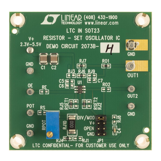
- Page 2 DC814 QUICK START GUIDE Table 2. Buffer Board Part Numbers Buffer Board Clock IC DC814A2-A LTC6905 DC814A2-B LTC1799 DC814A2C LTC6900 DC814A2-D LTC6905-133 DC814A2-E LTC6905-100 DC814A2-F LTC6905-96 DC814A2-G LTC6905-80 DC814A2-H LTC6906 DC814A2-I LTC6907 DC814A2-J LTC6908-1 DC814A2-K LTC6908-2 Figure 2. DC814C-X DIP-8 Clock Board A DC814A2-X is version two of the Buffer Board.
-
Page 3: Quick Start Procedure
DC814 QUICK START GUIDE 1. Remove DIP-8 clock board from buffer board 2. Set the jumper shunt on the DIP-8 clock board to the divider value, N, for the frequency range of interest (refer to Table 5). NOTE: On DC814D-J or K DIP-* board only N=1 is available in the JP1 1-2 position with spread spectrum modulation disabled. - Page 4 Table 3. Refer to the LTC6905 data sheet for a VCO design guide or to a May 2002 Linear Technology Magazine article: How to use the LTC6900 as a VCO.
- Page 5 DC814 QUICK START GUIDE Table 4. Frequency Accuracy for Fixed Frequency Oscillators LTC6905-133 (Board Version –D) LTC6905-96 (Board Version –F) N = 1, 133MHz; N = 2, 66.7MHz; N = 4, 33.5MHz N = 1, 96MHz; N = 2, 48MHz; N = 4, 24MHz Maximum Frequency Error at 25 °C: ±1.0% at V+=2.7V to 3.6V and ±1.5% Maximum Frequency Error at 25 °C: ±1.0% at V+=2.7V to 3.6V and ±1.5% typical at V+=5...
- Page 6 DC814 QUICK START GUIDE Table 5. Frequency Range and Accuracy of Resistor SET Oscillators. LTC6905 (Board Version –A) LTC6906 (Board Version –H) RSET = 3370/(2·Fosc·N-3), RSET = 100/(Fosc·N), (Fosc is in MHz and RSET in kΩ) (Fosc in MHz and RSET in kΩ) N = 1, 69MHz≤...
- Page 7 DC814 QUICK START GUIDE Arrow.com. Arrow.com. Arrow.com. Arrow.com. Arrow.com. Arrow.com. Arrow.com. Downloaded from Downloaded from Downloaded from Downloaded from Downloaded from Downloaded from Downloaded from...
- Page 8 DC814 QUICK START GUIDE Arrow.com. Arrow.com. Arrow.com. Arrow.com. Arrow.com. Arrow.com. Arrow.com. Arrow.com. Downloaded from Downloaded from Downloaded from Downloaded from Downloaded from Downloaded from Downloaded from Downloaded from...
- Page 9 DC814 QUICK START GUIDE Arrow.com. Arrow.com. Arrow.com. Arrow.com. Arrow.com. Arrow.com. Arrow.com. Arrow.com. Arrow.com. Downloaded from Downloaded from Downloaded from Downloaded from Downloaded from Downloaded from Downloaded from Downloaded from Downloaded from...
- Page 10 DC814 QUICK START GUIDE Arrow.com. Arrow.com. Arrow.com. Arrow.com. Arrow.com. Arrow.com. Arrow.com. Arrow.com. Arrow.com. Arrow.com. Downloaded from Downloaded from Downloaded from Downloaded from Downloaded from Downloaded from Downloaded from Downloaded from Downloaded from Downloaded from...
Need help?
Do you have a question about the LTC6905 Series and is the answer not in the manual?
Questions and answers