MullToa 65ai Service Manual
Hide thumbs
Also See for 65ai:
- User manual (40 pages) ,
- User manual (6 pages) ,
- Installation and user manual (24 pages)
Advertisement
Quick Links
Advertisement

Related Manuals for MullToa 65ai


Summary of Contents for MullToa 65ai
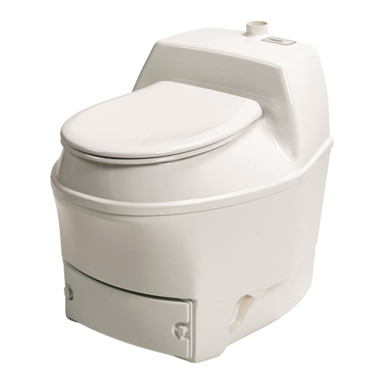
- Page 1 Servicemanual MullToa 55/65ai...
-
Page 2: Table Of Contents
Contents Page Update software, with pcb box Put display in service mode, for information Remove top part Disconnect and connect wires/cables, terminal block Remove Electrical panel 10-11 Replace Fanmotor 12-13 Replace shear pin Adjust level indicator, liquid Replace magnet sensor seat... -
Page 3: Update Software With Pcbbox
Update software with pcbbox Move the toilet away from the wall. Keep the toilet running Remove the cover located on the back of the toilet. Gently pull out the cable (visible inside) so you can access the connector. Connect the pcb-box to the con- nector. - Page 4 Update software with pcb box Press and release the white button on the pcb-box. The toilet turns off and a red light on the box indicate the software being updated. When its done, the red light goes off and the toilet restarts. The updating is finished.
- Page 5 Put the display in service mode First, press top button A and then lower button B. Hold both buttons down for about 10 seconds. A new meny will be shown on the display Shift meny by pressing but- ton A In the first window you will see Besök = Visits D = number of visits last 24hours V = number of visits last week...
-
Page 6: Remove Top Part
Remove top part NOTE! Before any service inside the toilet should be done the power must be disconnected. Move the toilet away from the wall. Remove the screw on the back of the toilet holding the top part. Remove the nut in front, under the toilet seat (holding the compost cover). -
Page 7: Disconnect And Connect Wires/Cables, Terminal Block
Disconnect and connect wires, terminal block 1. Remove top part (see page 6) Use a small regular screwdriver 2 -3 Push the screwdriver into the hole above the wire connection. Push gentle and the lock that keeps the wire will release. Gently pull the wire while pushing the screwdriver. - Page 8 Remove Electrical panel Sid 1/2 1. Remove the top part Loosen the quick release contact for the stirrer motor. Loosen the 3 contacts on top of the main pcb board on the back Note the order of these. Loosen the connection to the bottom heater. Either by loosening the wires in the terminal block (picture) or with quick release contact (depending on mo del).
- Page 9 Remove the Electrical panel Sid 2/2 Remove the panel from the toilet. To put the panel back, follow the points above, in reverse. Always check the function of the replaced component and the level indicator before the top part is put back.
- Page 10 Replacing Fanmotor 1. Remove the top part ( page 6) 2. Remove the electrical panel (page 8 and 9). Pull off the big fan blade at the back of the panel. Pull the fan blade off the shaft by hand without prying. 3.
- Page 11 Replacing Fanmotor 6. Remove the fan motor 7. Put in the new motor and make sure that the rubber gasket is centered. Fasten the two nuts and washers holding the motor. 8. Press the new fan blade onto the shaft. 9.
- Page 12 Replacing shearpin Take the top part off (page 6). Loosen the quick contact to stirrer motor Loosen the cable from pcb board and the power wires. Loosen the 4 screws holding the stirrer motor (the gearbox). Lift the motor.
-
Page 13: Replace Shearpin
Replace shearpin Remove the old shear pin, use a hammer and the new shear pin. Make sure that the shaft is resting on something solid. Put in a new shear pin. Use a hammer to knock it in. 8. Put the motor back and make sure that the bottom rake is in the correct position before mounting the motor. - Page 14 Adjusting the liquid level sensor Take the top part off (page 6) Make sure that the rod is standing on the float in the humus tray. The tray has to be empty and the float in position. Use a flash-light. Check the height of the indicator.
-
Page 15: Replace Magnet Sensor Seat
Replace magnet sensor seat Take the top part off (page 6) Remove the 2 philpsscrews holding the console above the motor Disconect the contact in the pcb (magnet sensor) Remove the screws holding the pcb board Mount the new pcb (magnet sensor), put the contact and consol back in re- versered order Mount the top part and test.
Need help?
Do you have a question about the 65ai and is the answer not in the manual?
Questions and answers