
Subscribe to Our Youtube Channel
Related Manuals for Hunter FLOW-SYNC HFS


Summary of Contents for Hunter FLOW-SYNC HFS
- Page 1 FLOW-SYNC Hunter Flow-Sync Flow Sensor for Use with Compatible Hunter Controllers Owner’s Manual and Installation Guide For more information visit hunterindustries.com...
-
Page 2: Table Of Contents
TABLE OF CONTENTS Introduction Flow-Sync Components System Overview and Flow-Sync Operation Installing the Flow-Sync Sensor & FCT Tee 12 Installing the Flow-Sync Sensor Into The FCT Fitting 14 Wiring the Flow-Sync to the Irrigation System 17 System Considerations 20 Troubleshooting Guide 23 Specifications and Calibration... -
Page 3: Introduction
INTRODUCTION Flow-Sync equips controllers to respond on The Hunter Flow-Sync allows flow-capable controllers, such as the Hunter ACC and I-Core, their own to incorrect system performance, to monitor actual flow in irrigation systems. preventing damage to landscape and wasted water resources. -
Page 4: Flow-Sync Components
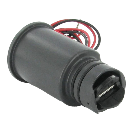
FLOW-SYNC COmpONENTS This section will give you a brief overview of some of the components of the Flow-Sync system. A. FLOW-SYNC Impeller: Rotates when flow is occurring 2 . O-rings: Provides sealing of sensor in sensor body 3. Wires: Black and red wires connect sensor to the ACC controller... - Page 5 B. FLOW-SYNC BOdY (FCT Series) Flow-Sync Tee: The Tee is installed into the irrigation system and houses the Flow-Sync 2 . plug (replace with Flow-Sync at installation) 3. O-rings: Provides sealing of plug in sensor body 4. Cap: Retains plug or sensor in sensor body 5.
-
Page 6: System Overview And Flow-Sync Operation
SYSTEm OVERVIEW AND FLOW-SYNC OpERATION As the impeller turns, pulses are generated to Flow-Sync is typically installed near the point of connection, in an appropriately-sized FCT Tee. the controller, which converts them to gallons or liters, depending on the Units of Measurement Flow-Sync can connect to the host controller selection in the controller. -
Page 8: Installing The Flow-Sync Sensor & Fct Tee
INSTALLING THE FLOW-SYNC SENSOR AND FCT TEE The Flow-Sync Sensor is designed to install For international applications, optional slip-BSP within an FCT tee fitting, sized for the pipe in adapters are available separately for sizes up to which it will be installed. 75 mm. - Page 9 Install the FCT tee fitting first, then install the • Flow-Sync requires a section of straight Flow-Sync Sensor into the fitting. pipe on either side of the tee fitting to provide accurate measurement of flow. Tees, ells, Observe the following general rules when choosing and other fittings cause turbulence which the sensor location and preparing to install: affects accuracy.
- Page 10 The FCT tee fitting is designed for glue (“slip”) • Example: FCT-200 is installed in a 2"/50 mm diameter pipe. The tee should have 20"/50 connection. Use approved PVC solvent-welding cm of straight pipe upstream, and 10"/25 cm glue to install either threaded fittings, or directly straight pipe downstream.
-
Page 12: Installing The Flow-Sync Sensor Into The Fct Fitting
INSTALLING THE FLOW-SYNC SENSOR INTO THE FCT FITTING To install the sensor into the body: The FCT tee fitting comes with a plug that allows for installation of the FCT into the irrigation Turn the system pressure off. system prior to installing the Sensor. This allows 2. - Page 13 5. Replace the cap on the sensor body. Hand tighten only. (figure 3). 6. Feed the two sensor wires through the hole in the cover and snap the cover on the cap. NOTE: Never glue the HFS sensor into the fitting! The threaded cap is designed to seal under pressure Figure 1 Figure 2...
-
Page 14: Wiring The Flow-Sync To The Irrigation System
(+) flow terminal in the controller. Connect the rated 18 AWG (1 mm) wires. Flow-Sync may also black lead from the sensor to the black (-) be used with Hunter ICD-SEN sensor decoders. terminal in the controller. Use only quality Wiring the Sensor... - Page 15 S3 in metal versions). the red wire to the positive side of the port. When used with a Hunter ICD-SEN sensor • Finish configuration as described in the decoder, consult the manual for the ICD-SEN.
- Page 16 ACC Controller I-Core Controller Use terminals S1 or S2 To ACC or to I-CORE Red wire Black wire Flow-Sync Sensor...
- Page 17 Proper irrigation system design and operation the irrigation system, the Flow-Sync can offer assures optimum performance of the Flow-Sync increased protection when components such as in monitoring for potential high flow conditions. sprays or rotors are damaged or removed due Flow-Sync is primarily designed to shut off the to vandalism.
-
Page 18: System Considerations
SYSTEm CONSIDERATIONS Working With Flow-Sync Hunter flow-capable controllers are designed active stations, to see if there is an unacceptable to measure and record actual flow, shut off difference, indicating a leak or break. irrigation when a high flow condition occurs, and Consult the controller documentation closely for identify which stations caused the condition. - Page 19 Mainline Pressure Fluctuation Some water sources may have varying pressure Additionally, excess air in irrigation piping causes depending upon the demand for water upstream the Flow-Sync impeller to spin freely during of the point of connection. During times of heavy station startup, which may cause temporarily demand, system pressure through the mainline high readings.
- Page 20 Proper System Maintenance and Operation It is important that your irrigation system be maintained and is functioning properly for optimum performance. Check your irrigation system for any broken components or leaks also, making sure that all sprinklers are operating within the pressure ranges recommended by the manufacturer.
- Page 21 Hunter controllers equipped with flow terminals When flow begins, the voltage will pulse. On a will haave approximately 20 VDC present on the standard voltmeter, the voltage will appear to flow sensor terminals, with no flow input. drop, or pulsate. On voltmeters equipped with a frequency counter, the pulse frequency can be measured in Hz.
-
Page 22: Troubleshooting Guide
TROUBLE-SHOOTING GUIDE Problem Cause Solution Flow-Sync not reading Water shut off Verify that no isolation valves are closed, and that the water source is on. Controller not configured Check controller flow sensor setup. Enter sensor size (and location, for sensor decoders) and other sensor information as required. - Page 23 Problem Cause Solution Flow-Sync not reading correctly Controller configured incorrectly Set correct flow sensor size and type at controller. Turbulent flow at sensor Insure that straight pipe is on either side of flow meter. Frequent false alarms Station settings too sensitive Increase overflow percentage (and underflow if available).
- Page 24 SpECIFICATIONS Flow Range Operating Specifications Flow-Sync Operating Range (Gpm) Temperature Pressures Humidity Sensor 0 to 140ºF/60ºC up to 200 psi/13.7 bar up to 100% Minimum* Suggested Maximum** diameter 1" 1½" 2" 3" 4" Minimum recommended flow for the highest flow zone for your system Good design practice dictates the maximum flow not to exceed 5ft/sec.
- Page 25 Maximum Distance Between Controller/Sensor Decoder and Sensor: 1000 ft/300 m Wire: 18 AWG/1 mm, 36”/1 m leads (Ø = diameter) Dimensions Straight Pipe Straight Pipe FCT Tee Fitting Height Width Length upstream (Ø x 10) downstream (Ø x 5) FCT 100 4.8″/12 cm 2.3"/6 cm 4.5"/11 cm...
- Page 26 Flow-Sync Calibration Factors Flow Sensor Values Hunter controllers allow selection of the correct Hunter Flow Sensor K-Factor Offset pipe size by FCT model number. No further HFSFCT100 0.44 0.39 HFSFCT150 1.13 0.00 calibration is needed. HFSFCT158 0.92 1.22 HFSFCT200 2.13 0.23...
- Page 27 NOTES...
- Page 28 Website hunterindustries.com Customer Support 760-744-5240 Technical Service 760-591-7383 © 2013 Hunter Industries Incorporated LIT-400 4/13...
Need help?
Do you have a question about the FLOW-SYNC HFS and is the answer not in the manual?
Questions and answers