Table of Contents
Advertisement
Quick Links
GENERAL GUIDE FOR
ICONNECTOR STHC
This chapter is to provide the general guides for all kind of iConnector with SKU: STHC. It includes the following guides:
* Principle of operation of iConnector STHC; * How to Wiring the iConnector * How to Config iConnector via offline cable;
* How to Configure Modbus commands for iConnector; * How to Configure Alarms & Event; * How to Trouble-shoot
iConnector; ...
General Information
I. Specification of iConnector STHC
II. Principle of operation of iConnector STHC
III. Offline configuration for iConnector
IV. Insert SIM Card for Cellular iConnector
V. Installation iConnector STHC
VI. How to add iConnector STHC to Globiots Server System?
VII. Modbus Configuration for iConnector STHC on Globiots
VIII. Parameter Configuration for iConnector STHC on Globiots
IX. Alarm & Event Configuration for iConnector STHC on Glbiots
X. Configuring special functions of iConnector on Globiots
XI. Troubleshooting iConnector and Globiots
Advertisement
Table of Contents

Related Manuals for daviteq iConnector STHC


Summary of Contents for daviteq iConnector STHC
- Page 1 This chapter is to provide the general guides for all kind of iConnector with SKU: STHC. It includes the following guides: * Principle of operation of iConnector STHC; * How to Wiring the iConnector * How to Config iConnector via offline cable;...
-
Page 2: General Information
Distributor in Australia and New Zealand Daviteq Technologies Inc No.11 Street 2G, Nam Hung Vuong Res., An Lac Ward, Binh Tan Dist., Ho Chi Minh City, Vietnam. Templogger Pty Ltd Tel: +84-28-6268.2523/4 (ext.122) Tel: 1800 LOGGER Email: info@daviteq.com | www.daviteq.com Email: contact@templogger.net... -
Page 3: Specification
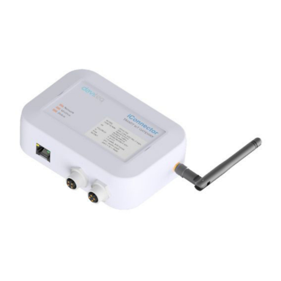
I. Specification of iConnector STHC 1.1 Introduction STHC is a Smart IoT Gateway, aka iConnector, a main component in any IoT application. iConnector has a role to connect the real World's things like sensors, meters, ,machines...to server system for data logging, data analytics, monitoring &... - Page 4 Back-up battery Lithium Super Capacitor On-board memory & sensors 2MB Flash, PCB temperature sensor Electrical connectors M12, 4-pin, coding A or 9mm Power Plug and USB port SIM slot 01 x micro-SIM (cellular versions only) Included accessories mounting bracket for wall mount (cellular version only) Operating Temperature/Humidity -20 ..
-
Page 5: Led Meaning
II. Principle of operation of iConnector STHC 2.1 General operation principles of iConnector 2.1.1 LED meaning 2.1.1.1 LED status Status Meaning Fixed ON iConnector has been supplied with external power Blinking (4 seconds blink 1 Without external power, iConnector is using battery. - Page 6 0x2300- The intrinsic data of iConnector 0x24FF 0x3000- 0x30FF 0x5000- FLASH 0x50FF 0x6000- 4096 Save data read from modbus slaves 0x6FFF Data address area: 0x2000-0x22FF (768 bytes), and 0x6000-0x6FFF (4096 bytes). Controller address area: 0x3000-0x30FF (256 bytes, without flash storage), and 0x5000-0x50FF (256 bytes, with flash storage).
- Page 7 PrmType Description # Byte Range BYTE 0 to 255 UINT16 0 to 65,535 UINT32 0 to 4,294,967,295 FLOAT -/+3.40282347 * (10^+38) INT16 -32,768 to 32,767 INT32 -2,147,483,648 to 2,147,483,647 2.1.7 Event The event table is 1024 bytes. The number of events depends on the short length of the event configured. Supported data types: PrmType Description...
-
Page 8: Apn Configuration
≤-113 to -95 Marginal 10-14 -93 to -85 15-19 -83 to -75 Good 20-31 -73 to ≥-51 Excellent not known or undetectable 2.2.2 GSM status Value Status Connect to the server: OK Connect to network operator: OK, the server is not connected yet Communicate with GSM modem with AT command: OK The GSM modem is starting 2.2.3 APN Configuration... - Page 9 2.3 iConnector Ethernet 2.3.1 What is TCP/IP ? 2.3.2 Configure with iConnector Config software Refer to section 5 for more details on how to use Configuration Cable 3.3.2.1 Ethernet tab Name Description...
- Page 10 Static IP configuration for iConnector. Example: 192.168.1.30 Gateway Configure gateway DNS Server Configure DNS Server 0 (Off) / 1 (On) DHCP If DHCP = 0, it's mean Not using DHCP → Static IP 3.3.2.2 Modbus-TCP-Server tab Name Description Modbus-TCP Port Configure the receiving port, for example 502 1 : To run transparent, interrupt modbus RTU poll.
- Page 11 2. The external internet network must also have a static IP, Example: IP 118.69.111.101 3. Network administrator must implement NAT port 502, TCP to IP of iConnector 4. At that time, TCP Client will connect to IP address 118.69.111.101 | Port 502 3.3.4.2 TCP Client read/write parameters on the iConnector memmap iConnector supports command 3 (0x03) for read, command 16 (0x10) for writing.
- Page 12 2.4.2 Configure using the Configuration Cable Refer to III. Offline configuration for iConnector for more details on how to use Configuration Cable Step 1: Open the configuration tool and switch to the Wifi tab; Step 2: Step 2: Configure the Wifi Name and Password that iConnector Wifi will connect to; Step 3: Check the Network LED.
-
Page 13: Configuration Cable
III. Offline configuration for iConnector iConnector need to be configured properly so that it is able to connect to Globiots Server successfully; 3.1 Preparation 3.1.1 Configuration Cable iConnector need to be configured initially before operation, by using a configuration cable as below: Item code Description RS485/USB multi-purpose Configuration cable with connector m12 male, female and... - Page 14 To configure the iConnector, there is a Software run on Windows OS (Window 10 is recommended); Please download the software at link below: https://filerun.daviteq.com/wl/? id=lNjzZbDo7Jwyr1x8DAD3x620tNK5u8lF Any desktop or laptop computer with USB-A port and Windows 10 OS can be used with this Software Unzip the file, it will extract 04 files as below picture: Double-click the application file, named: iconnector_config to run the application.
-
Page 15: Configuration Steps
3.2 Configuration Steps: Please follow these steps: Step 1: Plug the USB Step 2: Powering Plug the configuration cable to computer via USB Power supply 12 or 24VDC for Configuration Cable port; via DCSocket, by using the AC Adapter. Step 3: Connect to iConnector Plug the connector M12-Female to the RS485 port of iConnector (Right M12-male connector, as shown below picture) The LED "Status"... - Page 16 Press button "Connect" to allow the Software connect with iConnector If connect successful, you will see Status shows "connected" as below picture If NOT, Status shows "disconnected" 3.3 Configuration parameters for iConnector * There are many parameters of iConnector to be configured before using. * However, most of the parameters were configured by the manufacturer.
- Page 17 Typing the APN in the Setting column, then click the check box "Sync" at that row to allow the data to be written to iConnector. Once written successfully, you will see the same data on the "Value" Column; If the data on Value column is different from the data on Setting column, that meant the data has not been written successfully to iConnector.
- Page 18 =====END=====...
-
Page 19: Step 1: Remove The Housing
IV. Insert SIM Card for Cellular iConnector Steps to insert SIM card: Step 1: Remove the housing Using L hex key to unscrew M4 screws at the side of the housing and carefully pull out the top plastic housing in the vertical direction Step 2: Insert the SIM Card into the iConnector,... - Page 20 Step 3: Place back the housing and locking by L hex key ATTENTION: When reinstalling the cover, pay attention to put the PCB edge into the middle slot of the box inside as shown below)
-
Page 22: Example Application
V. Installation iConnector STHC 5.1 Example application iConnector is used widely in many applications for Smart Factory, Smart Facility/Building, Smart City, Smart Agriculture... Please refer more information at: https://www.daviteq.com/ung-dung2/ 5.2 Installation location Depend on what kind of iConnector, the location of installation will be considered carefully. - Page 23 5.2.2 if the iConnector has Cellular connectivity like 2G, 3G or 4G: We highly recommend to install the iConnector outdoor or outside of the cabinet so that it can have strong signal of cellular; Do not put iConnector inside a metallic box as the cellular can not go thru the metal sheets; Incase the iConnector must be place inside a box for better protection, please use the box with plastic materials like ABS, ASA, Polycarbonate, Fiber Glass...
- Page 24 5.3.2 iConnector with White housing: There are 02 holes for screwing at the left and right of housing. These holes are covered by the cover. Open the cover, you can access the hole for screwing. Using screw with size 4mm diameter maximum.
- Page 25 VI. How to add iConnector STHC to Globiots Server System?
- Page 26 VII. Modbus Configuration for iConnector STHC on Globiots...
- Page 27 VIII. Parameter Configuration for iConnector STHC on Globiots...
- Page 28 IX. Alarm & Event Configuration for iConnector STHC on Glbiots...
- Page 29 X. Configuring special functions of iConnector on Globiots...
- Page 30 XI. Troubleshooting iConnector and Globiots Phenomena Reason Solutions No power supply, the power cord is Check the power connection incorrectly connected Check the connection modbus A, Modbus connection pin A, B is loose or wrong Check the configuration of slave Configuration slave address, baudrate, parity Cannot read modbus...
Need help?
Do you have a question about the iConnector STHC and is the answer not in the manual?
Questions and answers