
Related Manuals for Sumitomo FA-20L


Summary of Contents for Sumitomo FA-20L
- Page 1 FA-20L Helium Compressor Operating Manual Sumitomo (SHI) Cryogenics of America, Inc. 1833 Vultee Street Allentown, PA 18103-4783 U.S.A. Revision C: March 2023 280682A...
-
Page 3: Table Of Contents
Helium Compressor, Model FA-20L ..............7 PRINCIPLES of OPERATION ..................9 DESCRIPTION ......................11 Components ..................... 11 SPECIFICATIONS ....................... 13 FA-20L Compressor (low voltage model) ............13 Electrical Characteristics ................. 13 Power Consumption ..................13 Compressor Control ..................14 Front Panel Connections ................... 14 Front Panel Mounted Items ................ - Page 4 Figure 16 Connect Self-Sealing Coupling ............37 Figure 17 Leak Check Aeroquip Couplings ............. 38 Figure 18 Fuse Holders on FA-20L Front Panel ..........43 Figure 19 Clean Heat Exchanger ..............43 Figure 20 FA-20L Compressor Wiring Diagram ..........49 Figure 21 FA-20L Compressor Wiring Schematic ...........
-
Page 5: Safety
SAFETY GENERAL SCAI equipment is designed to operate safely when the installation, operation and servicing are performed in accordance with the instructions in this technical manual. For Service Center locations, see the Service section of this manual. SPECIAL NOTICES Three types of special notices -- WARNINGS, CAUTIONS and NOTES are used in this technical manual. - Page 6 Safety WARNINGS AVOID ELECTRIC SHOCK. This equipment must only be connected to a supply mains switch with protective earth. All electrical supply equipment must meet applicable codes and be installed by qualified personnel. If this equipment is modified, appropriate inspection and testing must be conducted to ensure safe use of equipment.
- Page 7 Safety CAUTIONS PRESERVE YOUR WARRANTY. Modification to equipment without the consent of the manufacturer will void the warranty. Specifications require the use of 99.999% pure helium gas. Using a lesser quality of helium can damage the system and void the warranty. AVOID GAS LEAKS.
- Page 8 (This page is intentionally blank.)
-
Page 9: Service
SERVICE U.S.A. HEADQUARTERS Sumitomo (SHI) Cryogenics of America, Inc. 1833 Vultee Street Allentown, PA 18103-4783 Sales and Parts TEL: (800) 525-3072 (610) 791-6700 FAX: (610) 791-0440 Service TEL: (800) 525-3071 TEL: (610) 791-6750 SERVICE CENTERS Central Sumitomo (SHI) Cryogenics of America, Inc. - Page 10 (This page is intentionally blank.)
-
Page 11: Introduction
Self-sealing gas couplings allow for easy connection to and disconnection from the rest of the closed-cycle cryogenic refrigeration system. The information in this manual pertains only to the FA-20L (low voltage model) Compressor. Other components used to form an operating system are described in separate technical manuals. - Page 12 (This page is intentionally blank.)
-
Page 13: Principles Of Operation
PRINCIPLES of OPERATION Figure 1 Compressor Flow Diagram Helium discharge temperature switch Atmospheric relief valve Internal relief valve Solenoid valve Pressure gauge The compressor continuously draws low-pressure helium from the system return line. It compresses, cools and cleans the gas, then delivers it through the system gas supply line to the cold head. - Page 14 Principles of Operation When helium gas leaves the compressor capsule, the gas contains heat and compressor lubricant. Both must be removed. From the compressor capsule, the hot gas with its entrained oil flows out of the shell and through the bulk oil separator. The gas next flows through one circuit of a two-circuit, air-cooled, heat exchanger, where it is cooled.
-
Page 15: Description
Description Components 50/60 Hz Toggle Switch - This switch on the front electrical panel is used to select different phasing circuits for RDK-101D cold head operations at 50 or 60 Hz. Accessory Receptacle and optional Remote ON/OFF cable - The accessory receptacle on the front electrical panel is a 4-socket connector for supplying remote ON/OFF capability. - Page 16 Description Gas Equalization Solenoid Valve – This solenoid valve opens when the compressor shuts down, allowing helium gas pressure to equalize and prevent oil from moving into low pressure side of compressor. Gas Supply and Return Couplings - Located on the compressor front electrical panel, both are self-sealing, size #8, male bulkhead couplings and are the points of connection for system gas lines.
-
Page 17: Specifications
SPECIFICATIONS FA-20L Compressor There are two electrical voltage variations: Compressor P/N Mains Voltage 280504D18N 208-230 VAC +/- 10%, V~ 60 Hz and 200 VAC +/- 10%, V~ 50 Hz 280504D27N 220 - 240 VAC +/- 10%, V~ 50 Hz 265 VAC +/- 10%, V ~ 60 Hz Electrical Characteristics Service required: 2 poles, 3 wires (single phase plus protective ground.) -
Page 18: Compressor Control
Automatic shutoff for the following system faults. Operator correction is required before restart. High helium gas discharge temperature [TSG] when > 93° C (200° F) High compressor motor windings temperature. FA-20L P/N Switch Opens Switch Resets 280504D18N 145° C 69-87° C (293°... -
Page 19: Mounting Position
Specifications Mounting Position Compressor must be mounted base down and level within 5 degrees of horizontal. Heat Rejection to Room 60 Hz 2.75 kW 50 Hz 2.35 kW Helium Gas Pressures Equalization Pressure ① Application Flex Gas Line at 20° C (68° F) RDK-101D Cold Head, 50/60 Hz 210 psig ؽ... -
Page 20: Maintenance Intervals
Normal pressure and temperature data are listed above. User should record monthly the operating conditions in a logbook. Keep this record of data for reference and later comparisons. Supplier Name and Address Sumitomo (SHI) Cryogenics of America, Inc. 1833 Vultee Street Allentown, PA 18103-4783 U.S.A. -
Page 21: Regulatory Compliance
Manufacturer’s Name Sumitomo (SCAI) Cryogenics of America Manufacturer’s Address 1833 Vultee Street Allentown, PA 18103 U.S.A. Authorized Representative’s Name Sumitomo (SHI) Cryogenics of Europe GmbH Authorized Representative’s Address Daimlerweg 5a D-64293 Darmstadt Germany Authorized Representative’s Contact Tel: +49 (0) 6151-860-610... - Page 22 Specifications UKCA Declaration of Conformity Manufacturer’s Name Sumitomo (SCAI) Cryogenics of America Manufacturer’s Address 1833 Vultee Street Allentown, PA 18103 U.S.A. Authorized Representative’s Address 3 Hamilton Close Houndmills Industrial Estate Basingstoke Hampshire RG21 6YT United Kingdom Authorized Representative’s Contact Tel: +44 (0) 1256 853333...
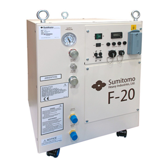
- Page 23 Specifications Figure 2 FA-20L Compressor, Front View Figure 3 FA-20L Compressor, Dimensions Dimensions are in inches and [mm].
- Page 24 Specifications (This page is intentionally blank.)
-
Page 25: Installation
Installation Introduction Install the FA-20L Compressor, Mains Power Cable and the Gas Lines according to the following procedures. The following installation procedures are based on standard arrangements of equipment, using SCAI standard components. To prevent contaminating the components or the system, it is important to follow the procedures in this manual step by step. -
Page 26: Unpackaging And Product Inspection Instructions
Installation 3. Upon receipt, inspect Tip-N-Tell Sensor on Package for Activation 3.1 The Tip-N-Tell sensor mounted on the shipping container package surface should be checked upon receipt and before unpackaging to verify the “Compressor Unit shipping container” was NOT tipped or mishandled during transport. 3.2 If activated, Tip-N-Tell sensor turns blue in the arrow as shown below. - Page 27 Installation 2.2 The equalization pressure is within specifications: If the compressor has been momentarily tipped (less than one hour) and the equalization pressure is within specifications, allow it to stand upright for two hours before performing this step AVOID ELECTRIC SHOCK. This equipment must only be connected to a supply mains with protective earth.
-
Page 28: Compressor Location
Installation Compressor Location Place the compressor in a location that is protected from the elements and where the ambient temperature will always be within the range of 4° C to 40° C (40° F to 104° F). The compressor must be installed base down, within 5 degrees of horizontal. The compressor must be installed in a location allowing proper airflow. -
Page 29: Electrical Supply Connection - Field Wiring Instructions
Tool required: #3 Phillips screwdriver 5 mm Hex driver The FA-20L compressor must be installed in a circuit capable of supplying the specified voltage and power. The wiring method used for connection to the front panel power connector must meet applicable codes. -
Page 30: Compressor Checkout
Installation Compressor Checkout The compressor should be operated before being connected to the other system components. 1. Ensure that the circuit breaker on the compressor is open (handle is down). 2. Supply power to the compressor. 3. Close the circuit breaker (handle up). 4. - Page 31 Installation Figure 6 Attach Identification Label 2. Arrange the system components so that the gas lines will be protected from stress and traffic. Observe the minimum bend radius of 180 mm (7") when routing gas lines. Provide supports where needed. 3.
-
Page 32: Install The Cold Head Cable(S)
Installation 6. Using two wrenches, connect the SUPPLY gas line to the SUPPLY coupling on the cold head. Tighten the coupling to 47 ± 7 Nm (35 ± 5 ft. lbs.). The system equalization pressure, shown by the compressor gauge after all components have been connected, will determine if charging or venting is required. -
Page 33: Prestart Check
Installation Prestart Check 1. Check that all electric connections are made: a. Power to the compressor b. Cold head cable 2. Check that the mains circuit breaker switch is open (handle is down) and the electrical power supply is switched ON. 3. - Page 34 (This page is intentionally blank.)
-
Page 35: Operation
OPERATION Starting Close the circuit breaker by pushing up the handle. Press the power switch. The indicator in the switch will light. The compressor will start. Any items drawing power from the compressor will start. Verify cooling fan is running and there is airflow out of the top of the compressor. - Page 36 (This page is intentionally blank.)
-
Page 37: Maintenance
MAINTENANCE Adsorber Replacement Part required: Adsorber, P/N F300138A Tools required: #2 Phillips screwdriver Open-end wrenches, 1", 1 1/8", 1 3/16" ® Snoop AVOID EQUIPMENT FAILURE OR CONTAMINATION. Use SHIG adsorber P/N F300138A only. Use of non-SHIG spare parts will void the warranty. The compressor’s adsorber should be replaced every 30,000 operating hours (40 months). - Page 38 Maintenance 4. Using two wrenches to disconnect the self-sealing coupling on the inlet side of the adsorber. See Figure 9. Figure 9 Disconnect Self-Sealing Coupling 5. Use a Phillips screwdriver to remove the two screws holding the adsorber to the base. See Figure 10.
- Page 39 Maintenance 6. Remove the locknut on the Aeroquip supply coupling on the front panel. See Figure 11. Figure 11 Remove Supply Coupling Locknut 7. Pull the adsorber back until the supply coupling clears the front panel. Remove the adsorber. Remove the lock washer from the Aeroquip supply coupling. Retain all hardware to reuse with the new adsorber.
-
Page 40: Adsorber Installation
Maintenance Adsorber Installation 1. Remove the dust caps from the gas couplings of the new adsorber. Do not vent the new adsorber. 2. Install the lock washer on to the supply coupling of the new adsorber. Insert the supply coupling through the front panel and position the adsorber. See Figure 13. Figure 13 Install Lock Washer on Adsorber 3. - Page 41 Maintenance 4. Install the red nylon washer and the locknut on the supply coupling. Torque the locknut to 54 Nm (40-ft. lbs.). See Figure 15. Figure 15 Install Supply Coupling Washer and Locknut 5. Connect the adsorber’s self-sealing coupling on its inlet side to the oil separator’s outlet coupling.
-
Page 42: Used Adsorber Venting And Disposal
Maintenance ® ® 7. Using Snoop , leak check all Aeroquip couplings just completed. Wipe off the Snoop prevent rusting. See the Leak Check procedure in Maintenance in this manual. See Figure Figure 17 Leak Check Aeroquip Couplings 8. Check the equalization pressure. See Specifications in the Operating Manual. 9. -
Page 43: Charging Procedure
Maintenance AVOID INJURY. Never use compressed helium gas from a cylinder without a proper regulator. Overpressure can cause serious injury if the system equipment ruptures. AVOID CONTAMINATION. Follow the charging and venting procedure to prevent reversed flow of system gas. Do not charge through the supply coupling. -
Page 44: Venting Procedure To Adjust Equalization Pressure
Maintenance 7. Adjust the regulator to the required equalization pressure. See the Specifications section. Slowly open the valve on the charge and vent tool. Charge the system with helium gas to the equalization pressure. 8. Close the valves on the charge and vent tool and on the gas cylinder. 9. - Page 45 Maintenance AVOID INJURY. Disconnect gas lines only when the compressor is stopped. Disconnecting the cold head while it is cold can create excessively high internal pressure as the gas warms. Material failure and uncontrolled pressure release can cause serious injury. Gas cleanup is required if the compressor’s interior has been opened to the atmosphere or the equalization pressure is 1.4 bar (20 psig) or lower.
-
Page 46: Fuse Replacement
Fuse Replacement Tool required: Flat screwdriver Fuses for the FA-20L are located in the front panel of the electrical chassis of the compressor Control circuit (FU-1, FU-2, FU-3 and FU-4 ) as shown in Figure 18: a. Four (3) 1AT , 250V For FU-1, FU-2, FU-3 and FU-4 1. -
Page 47: Heat Exchanger Cleaning
Fuse Holder Figure 18 Fuse Holders on FA-20L Front Panel Heat Exchanger Cleaning Heat exchanger cleaning to remove collected dust and debris is required regularly to maintain proper compressor operation. Cleaning is recommended twice a year, but it may be necessary more often, depending on the operating environment. - Page 48 Maintenance AVOID INJURY. Do not touch heat exchanger fins. Fins are sharp and may cause injury. PREVENT EQUIPMENT DAMAGE. Do not insert object or admit fluids through fan guard under any circumstances. Injury or malfunction may occur.
-
Page 49: Troubleshooting
TROUBLESHOOTING Automatic Shutdown The compressor will not start or will shut down automatically if any of the following are open: the compressor motor protector switch; the gas high-temperature switch; the motor over-current relay; the circuit breaker. If the compressor has been shut down by one of these interlocks, do not restart until the problem has been found and corrected. - Page 50 Troubleshooting Troubleshooting Guide The Troubleshooting Guide that follows lists problems that can occur in the system and suggests causes and corrective actions. Problem Possible Cause Corrective Action Compressor and items No electrical power. Check that the power source powered by it do not start is “ON”...
- Page 51 Troubleshooting Problem Possible Cause Corrective Action Compressor starts but shuts down sometime later. Circuit breaker or fuse is Reset the Circuit breaker or open. replace a fuse. Compare the electric service with system specifications. Consult a SCAI Service Center if the problem persists.
- Page 52 Troubleshooting Problem Possible Cause Corrective Action Compressor runs, but cold Wrong cold head cable. Ensure correct cold head head valve motor operation is cable is connected per “Install abnormal. the Cold Head Cable(s)” procedure and visual inspection. Cold head problem. Consult cold head manual.
- Page 53 Troubleshooting Figure 20 FA-20L Compressor Wiring Diagram...
- Page 54 Troubleshooting Figure 21 FA-20L Compressor Wiring Schematic...
-
Page 55: Parts
Refer to the next section for Parts Identification and Numbers. Installation Tool Kit The following installation tool kit is used for installing or servicing the FA-20L compressor and is available as an accessory from SCAI Installation tool kit P/N 267990A consists of:... -
Page 56: Cables
Parts Cables The following cables are available for use with the FA-20L Series Compressors as accessories from SCAI. Item Quantity Description Part Number Mains Power Supply Cable, FA-20L, 3 m (10 ft.) 280112C10* long. Remote On/Off Cable, 6 m (20 ft.) long.
Need help?
Do you have a question about the FA-20L and is the answer not in the manual?
Questions and answers