Sumitomo F-70H Service Manual

Sumitomo F-70H Service Manual

Helium compressors

Advertisement

F-70H and F-70L Helium
Compressors
Service Manual
Sumitomo (SHI) Cryogenics of America, Inc.
1833 Vultee Street
Allentown, PA 18103-4783
U.S.A.
Revision C: March 2012
267056A

Advertisement

Table of Contents
loading
Need help?

Need help?

Do you have a question about the F-70H and is the answer not in the manual?

Questions and answers

Subscribe to Our Youtube Channel

Summary of Contents for Sumitomo F-70H

  • Page 1 F-70H and F-70L Helium Compressors Service Manual Sumitomo (SHI) Cryogenics of America, Inc. 1833 Vultee Street Allentown, PA 18103-4783 U.S.A. Revision C: March 2012 267056A...
  • Page 3: Table Of Contents

    TABLE of CONTENTS Page SAFETY.......................... 1 SERVICE ........................5 INTRODUCTION ......................7 
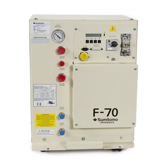
Helium Compressors, Models F-70H and F-70L ..........7 PRINCIPLES of OPERATION ..................9 DESCRIPTION ......................11 Components ....................11 MAINTENANCE ........................13 Connect and Remove the Water Lines ..............13 Adsorber Replacement ....................
  • Page 4 Figure 2 Connect and Remove the Water Lines ..........14 Figure 3 Electrical Chassis ................27 Figure 4 F-70H Compressor Wiring Diagram ..........36 Figure 5 F-70H Compressor Wiring Schematic ..........37 Figure 6 F-70L Compressor Wiring Diagram ........... 38 Figure 7 F-70L Compressor Wiring Schematic ..........
  • Page 5: Safety

    SAFETY GENERAL SHI equipment is designed to operate safely when the installation, operation and servicing are performed in accordance with the instructions in this technical manual. For Service Center locations, see the Service section of this manual. SPECIAL NOTICES Three types of special notices -- WARNINGS, CAUTIONS and NOTES are used in this technical manual.
  • Page 6 Safety WARNINGS AVOID ELECTRIC SHOCK. This equipment must only be connected to a supply mains switch with protective earth. All electrical supply equipment must meet applicable codes and be installed by qualified personnel. If this equipment is modified, appropriate inspection and testing must be conducted to ensure safe use of equipment.
  • Page 7 Safety CAUTIONS (continued) AVOID GAS LEAKS. Check the condition of the gasket face seal on the male half of each Aeroquip coupling. Be sure the gasket face seal is in place and the sealing surfaces on both the male and female halves are clean before connecting. Replace the gasket face seal if it is damaged or missing.
  • Page 8 (This page is intentionally blank.)
  • Page 9: Service

    SERVICE HEADQUARTERS Sumitomo (SHI) Cryogenics of America, Inc. 1833 Vultee Street Allentown, PA 18103-4783 Sales and Parts TEL: (800) 525-3072 (610) 791-6700 FAX: (610) 791-0440 Service TEL: (800) 525-3071 TEL: (610) 791-6750 SERVICE CENTERS Eastern Sumitomo (SHI) Cryogenics of America, Inc.
  • Page 10 (This page is intentionally blank.)
  • Page 11: Introduction

    Self-sealing gas couplings allow for easy connection to and disconnection from the rest of the closed-cycle cryogenic refrigeration system. The information in this manual pertains only to the F-70H (high voltage model) and the F-70L (low voltage model) Compressors. Other components used to form an operating system are described in separate technical manuals.
  • Page 12 (This page is intentionally blank.)
  • Page 13: Principles Of Operation

    PRINCIPLES of OPERATION Figure 1 Compressor Flow Diagram Gas temperature thermistor TSWi Water-in temperature thermistor TSWo Water-out temperature thermistor Atmospheric relief valve Internal relief valve Solenoid valve Pressure transducer Pressure gauge The compressor continuously draws low-pressure helium from the system’s helium low pressure (return) line.
  • Page 14 (This page is intentionally blank.)
  • Page 15: Description

    DESCRIPTION Components Adsorber - The adsorber removes any oil and moisture the gas is carrying which did not drop out in the separator. The adsorber has a finite life and must be replaced every 30,000 operating hours. Atmosphere Relief Valve [ARV] – The pressure relief valve prevents the compressor from operating at an unsafe pressure by venting to the atmosphere.
  • Page 16 High outlet water temperature indicates low water flow. Water In and Out Fittings – F-70H is fitted with two (2) ½" MNPT and F-70L is fitted with two (2) ½” Serto elbows mounted on the front panel.
  • Page 17: Maintenance

    MAINTENANCE AVOID EXPOSURE. People with pacemakers, defibrillators or ferrous implants should avoid exposure to strong magnetic fields. The long-term effects of high magnetic fields are not well understood. Keep personal exposure to a minimum. AVOID INJURY. When released in a high magnetic field, ferrous tools and parts can become hazardous projectiles.
  • Page 18: Adsorber Replacement

    Maintenance Hold jam nut with one wrench Turn water line coupling with the other wrench Figure 2 Connect and Remove the Water Lines Adsorber Replacement Part required: Adsorber, P/N F300138A Tools required: #2 Phillips screwdriver Open-end wrenches, 1", 1 1/8", 1 3/16" ®...
  • Page 19: Adsorber Installation

    Maintenance 5. Use a Phillips screwdriver to remove the two screws holding the adsorber to the base. 6. Remove the locknut on the Aeroquip supply coupling on the front panel. 7. Pull the adsorber back until the supply coupling clears the front panel. Remove the adsorber.
  • Page 20: Used Adsorber Venting And Disposal

    Maintenance 4. Press the ON control button. Display will show “SAVE? Y-ON N-OFF.” 5. Press the ON control button again to complete. (Press the OFF control button to back out of the function.) When ON is pressed, display will show: “Saving New ADS”. When function is complete, display will again show “NEW ADS? ON=Yes.”...
  • Page 21: Charging Procedure

    Maintenance AVOID CONTAMINATION. Follow the charging and venting procedure to prevent reversed flow of system gas. Do not charge through the supply coupling. Do not vent through the return coupling. Reversed flow can contaminate the system with compressor oil. NOTE Adapter fittings for charging and venting are available as optional service tools.
  • Page 22: Venting Procedure To Adjust The Equalization Pressure

    Maintenance 10. Leak check the Aeroquip couplings using the Leak Check procedure in this manual This completes the charging procedure. Venting Procedure to Adjust the Equalization Pressure NOTE This venting procedure is not to be used for gas cleanup of the compressor. To vent helium gas from the system: 1.
  • Page 23 Maintenance AVOID ASPHYXIATION. Be sure the work area is well ventilated. AVOID INJURY. Disconnect gas lines only when the compressor is stopped. Disconnecting the cold head while it is cold can create excessively high internal pressure as the gas warms. Material failure and uncontrolled pressure release can cause serious injury.
  • Page 24: Cold Head Gas Cleanup

    Maintenance 13. Allow the compressor to cool. Read the pressure gauge with the compressor at 20° C (68° F). Adjust the equalization pressure by charging or venting to conform to the Specifications. 14. Close the gas cylinder valve and adjust the pressure regulator to zero psig. 15.
  • Page 25: Leak Repair

    Maintenance The flat gasket in the face of the Aeroquip male coupling seals the joint. A leak at this gasket face seal can be detected only when a gas line is connected. A leak here can be caused by: the coupling not fully tightened; •...
  • Page 26: Replace A Nylon Slide Rail

    Maintenance Replace a Nylon Slide Rail Part Required: Slide rail, P/N 267033B Tool required: #2 Phillips screwdriver NOTE This procedure assumes that the compressor’s casters have been removed. 1. Elevate the compressor for access to its bottom. Do not tip the compressor more than 10 degrees.
  • Page 27: Replace A Lifting Eyebolt

    Maintenance Replace a Lifting Eyebolt Part required: Eyebolt, P/N 73216 Tool required: Screwdriver or wrench extension, if required 1. Use a tool through the eyebolt for removal if it is too tight to turn by hand. 2. Inert a replacement eyebolt. Tighten it hand tight or slightly more by use of a tool to turn it.
  • Page 28 (This page is intentionally blank.)
  • Page 29: Troubleshooting

    4. With an ohmmeter, check the resistance across pairs of compressor terminals. Line to line motor resistance for the F-70H compressor capsule should be about 2.27 ± 10% ohms, at room temperature. Line to line motor resistance for the F-70L compressor capsule should be about 0.56 ±...
  • Page 30: Replace Fuses

    AVOID ELECTRIC SHOCK. Disconnect the power to the compressor before troubleshooting the electrical components. Three (3) Class CC time delay fuses (1.0 ampere for F-70H, 2.0 amperes for F-70L), FU-1, FU- 2 and FU-3, are located in the electrical chassis box. See Figure 3.
  • Page 31: Replace The Electrical Chassis

    FU-2, FU-3 Fuses, FU-4, FU-5, FU-6 Figure 3 Electrical Chassis Replace the Electrical Chassis Parts required: P/N F267109A for F-70H P/N F267097A for F-70L Tools required: Flat blade screwdriver #2 Phillips screwdriver Phillips torque screwdriver, 2.0 Nm (18 in. lbs.)
  • Page 32: Replace The Supply Gas High Temperature Thermistor

    Troubleshooting 1. Read and record the elapsed time on the LCD display of the old unit. Contact a Service Center to report the elapsed time meter reading. AVOID ELECTRIC SHOCK. Disconnect the power to the compressor before troubleshooting the electrical components. 2.
  • Page 33: Replace The Water High Temperature Thermistors (Thermistor Cable Assembly)

    Troubleshooting 2. Using a Phillips screwdriver, remove the compressor’s cover. Retain the screws and lock washers for reinstallation. 3. The gas temperature thermistor is fastened to the compressor discharge gas tube coming out of the compressor head (located at the rear of the entire compressor package). With the needle nose pliers, disconnect the two wires from the switch.
  • Page 34: Automatic Restarting After A Helium High Temperature Shutdown Error

    Troubleshooting Automatic Restarting After a Helium High Temperature Shutdown Error If a helium discharge high temperature shutdown error causes a shutdown of the system, the compressor will attempt to restart itself 5 times at 20 minute intervals before a reset signal must be provided to the compressor.
  • Page 35: Clearing Error Conditions

    Troubleshooting LCD Display Type Error Indication First Line Helium Temp- Shutdown High helium discharge Temperature > 93° C (200° F) temperature Water Temp- Alarm High water supply Temperature > 35° C (95° F). temperature. Water Flow-ERR Alarm Low water flow Temperature >...
  • Page 36: Restarting After An Error Condition

    Troubleshooting Restarting After an Error Condition When the shutdown is caused by helium discharge high-temperature, the compressor will be able to restart only after it has cooled enough for the thermistor to read a temperature below the cut-off point. After waiting for the compressor to cool, clear the error message then push the ON button to restart.
  • Page 37: Troubleshooting Guide

    Troubleshooting C) Run Hours o Returns display run time (run hours since last service) o Returns master run time (run hours since manufacture) D) Return Pressure o Returns current return pressure in bar and psig E) Temperatures o Returns current operating temperatures F) Adsorber Life o Returns remaining adsorber life in hours G) Register New Adsorber...
  • Page 38 Troubleshooting Problem Possible Cause Corrective Action LCD reads Motor Temp- Compressor capsule internal thermal protector open Note: This fault is inferred Low supply voltage Check mains voltage; correct if from detection of high return outside the specifications. pressure. Under normal Excessive helium See Specifications in Operating conditions, high return...
  • Page 39: Compressor Reset Functions

    Troubleshooting Problem Possible Cause Corrective Action LCD reads Return Press- Low helium gas charge See Helium Gas Pressure Specifications in the Operating Return pressure transducer Manual Note: Low return pressure. fault Replace transducer Set point is 15 psig PCB 1 fault Replace PCB 1 LCD reads Water Temp- High supply water...
  • Page 40 Troubleshooting Figure 4 F-70H Compressor Wiring Diagram...
  • Page 41 Troubleshooting Figure 5 F-70H Compressor Wiring Schematic...
  • Page 42 Troubleshooting Figure 6 F-70L Compressor Wiring Diagram...
  • Page 43 Troubleshooting Figure 7 F-70L Compressor Wiring Schematic...
  • Page 44 NOTE Be sure to have 99.999% pure helium gas available for servicing the system. Variations for electrical service: F-70H for 480 (±10% V3~, 60 Hz and 380/415 (±10%) V3~, 50 Hz. F-70L for 200 (±10%) V3~, 50/60 Hz. F-70H Compressor Parts...
  • Page 45 Parts F-70H and F-70L Compressor Parts Item Quantity Part Name Part Number Adsorber assembly F300138A Gas temperature thermistor 267049A Cable assembly with water temperature switches 267039B 267129A Water Fitting Kit, including: (2) Elbow, 90° Swivel, brass, ½” hose barb to ½” BSP, Serto...
  • Page 46 (This page is intentionally blank.)

This manual is also suitable for:

F-70l

Table of Contents

Save PDF