Sign In
Upload
Download
Table of Contents
Contents
Add to my manuals
Delete from my manuals
Share
URL of this page:
HTML Link:
Bookmark this page
Add
Manual will be automatically added to "My Manuals"
Print this page
×
Bookmark added
×
Added to my manuals
Manuals
Brands
Sumitomo Manuals
Air Compressor
HC-4E1
Technical manual
Sumitomo HC-4E1 Technical Manual
Helium compressors
Hide thumbs
1
2
Table Of Contents
3
4
5
6
7
8
9
10
11
12
13
14
15
16
17
18
19
20
21
22
23
24
25
26
27
28
29
30
31
32
33
34
35
36
37
38
39
40
41
42
43
44
45
46
47
48
49
50
51
52
53
54
55
56
57
58
59
60
61
62
63
64
page
of
64
Go
/
64
Contents
Table of Contents
Troubleshooting
Bookmarks
Table of Contents
Table of Contents
Safety
Service
Introduction
Helium Compressor Models HC-4E1 and HC-4E2
Principles of Operation
Description
Components
Specifications
Electrical Characteristics
Cooling Requirements
Refrigerant Quality
Helium Gas Pressures
Compressor Lubricant
Compressor Weight
Compressor Dimensions
Space Requirements
Mounting Position
Environmental Requirements
Protective Earth Terminal
Maintenance Intervals
Installation Kit
Adapter Fittings (Optional Accessory)
Remote On/Off Cable (Optional Accessory)
Supplier Name and Address
Regulatory Compliance
Installation
Introduction
Receipt Inspection Instructions
Compressor Position
Mains Power Supply Connection
Table 1 Terminal Position for Mains Power Supply
Field Wire the Compressor
Compressor Checkout
Interconnections
Remote On/Off Cable (Optional Accessory)
Compressor Shipping Preparation
Operation
Prestart Check
Starting
Stopping
Restarting after a Power Failure
Maintenance
Adsorber Replacement
Adsorber Removal
Adsorber Installation
Used Adsorber Venting and Disposal
Charging and Venting
Charging Procedure
Venting Procedure to Adjust the Equalization Pressure
Venting Procedure to Vent to Atmospheric Pressure
Gas Cleanup
Leak Check
Leak Repair
Replace the Compressor Shell High Temperature Switch
Troubleshooting
Automatic Shutdown
Troubleshooting Guide
Compressor Capsule
Winding Continuity, Grounding and Resistance Checks
Current Measurement
Parts
Ordering
Compressor Parts Identification and Numbers
Adapter Fittings
Cables
Advertisement
Quick Links
1
Helium Compressor Models Hc-4E1 and Hc-4E2
2
Specifications
3
Electrical Characteristics
4
Cooling Requirements
Download this manual
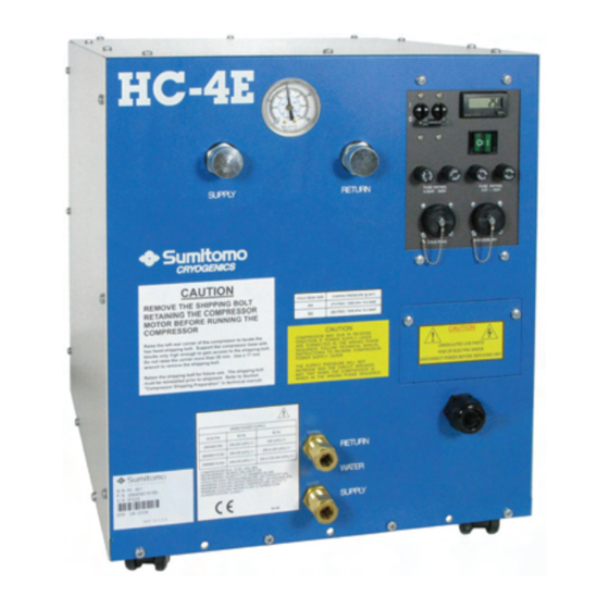
HC-4E1 and HC-4E2 Helium
Compressors
Technical Manual
Sumitomo (SHI) Cryogenics of America, Inc.
1833 Vultee Street
Allentown, PA 18103-4783
U.S.A.
Revision C: August 2012
267318A
Table of
Contents
Previous
Page
Next
Page
1
2
3
4
5
Advertisement
Table of Contents
Troubleshooting
TROUBLESHOOTING
49
Troubleshooting Guide
50
Need help?
Do you have a question about the HC-4E1 and is the answer not in the manual?
Ask a question
Questions and answers
Related Manuals for Sumitomo HC-4E1
Air Compressor Sumitomo HC-4A Technical Manual
Air-cooled helium compressors (72 pages)
Air Compressor Sumitomo HC-4E2 Technical Manual
Helium compressors (64 pages)
Air Compressor Sumitomo F-70H Service Manual
Helium compressors (46 pages)
Air Compressor Sumitomo F-20L Operating Manual
(56 pages)
Air Compressor Sumitomo FA-20L Operating Manual
Helium compressor (56 pages)
This manual is also suitable for:
Hc-4e2
Table of Contents
Save PDF
Print
Rename the bookmark
Delete bookmark?
Delete from my manuals?
Login
Sign In
OR
Sign in with Facebook
Sign in with Google
Upload manual
Upload from disk
Upload from URL


Need help?
Do you have a question about the HC-4E1 and is the answer not in the manual?
Questions and answers