Grape Solar GS-PWM-20A - 12/24V 20A PWM Charge Controller Manual
- Quick connect manual (2 pages) ,
- User manual (12 pages) ,
- Quick connect manual (2 pages)
Advertisement
- 1 Warnings and Tools Icon Chart
- 2 Product Features
- 3 Device Diagram
- 4 Mounting Instruction
- 5 Wire Connection Sequences
- 6 LCD Display Interface Overview
- 7 Key Functionality Chart
- 8 LCD Display Rules & Cycles
- 9 Error Code Chart
- 10 Controller Specification
- 11 Product Dimensions
- 12 Documents / Resources
Warnings and Tools Icon Chart
| Icons | Name | Description |
 | High Voltage | High voltage device. Installation should be performed by an electrician. |
 | High Temperature | This device will produce heat. Mount device away from other items. |
 | Environmental Hazard | Electronic Equipment. Do not put in landfill. |
 | Wire Cutter | A wire cutter is needed for cutting and stripping wires prior to connection. |
 | Multimeter | A multimeter is needed for testing equipment and verifying polarity of cables. |
 | Anti-static Glove | Anti-static gloves are recommended to prevent controller damage caused by static electricity. |
 | Electrical Tape | Electrical tape is recommended to safely insulate spliced or bare wires. |
 | Screwdriver | A common size screwdriver is needed when attaching wires to the controller. |
Product Features
Thank you for choosing Grape Solar. This PWM solar charge controller is a device for solar charge regulation and direct current output load control. This device is mainly used in small sized o -grid solar power systems.
The Grape Solar PWM-20A charge controllers have these features:
- Charging modes available for most common deep-cycle battery types in the market, including AGM (sealed lead acid batteries), GEL, Flooded, and Lithium mode with customizable parameters.
- Automatic recognition of 12V/24V battery system.
*Lithium-ion batteries excluded from this feature. - 5V 1A USB outlet provides charging for mobile devices.
- Provides multiple load control mode options for light based, time based and manually adjusted scenarios.
- Industrial grade design with reverse polarity protection for solar panels, battery and load.
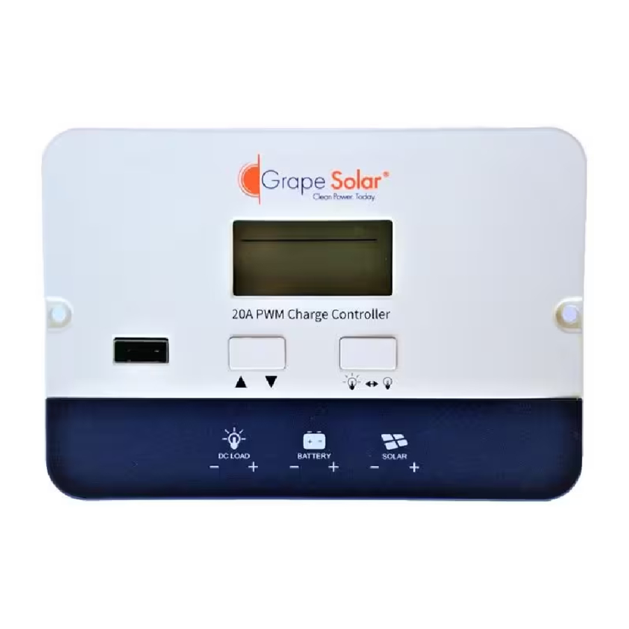
Device Diagram

| # | Description | # | Description |
| 1 | LCD Display Screen | 6 | Battery Terminals |
| 2 | 5V 1A USB Port | 7 | Load Terminals |
| 3 | Arrow Key | 8 | Installation Mounting Holes |
| 4 | Load Key | 9 | Flat Mount Bracket |
| 5 | Solar Terminals |
Mounting Instruction
This controller can be mounted flush or flat with included bracket at a cool, dry and weather safe location.

- Attach the mounting bracket to the back of the controller using screws.
- Mark the bracket's mounting holes on the mounting surface.
- Attach the mounting bracket to the mounting surface using screws.

- Mark the controller's dimension and mounting holes on the mounting surface.
- Make necessary alterations to ensure the controller fits into the mounting surface snugly. Pre-install wires if needed (turn to next page for instructions).
- Attach the controller to the mounting surface using screws.
Wire Connection Sequences

During installation of your PWM controller, please follow below order of connection:
- Connect the positive battery wire followed by the negative battery wire.
- Make sure your solar panels are fully covered to prevent electrical shock. Connect the positive solar array output wire followed by the negative solar array output wire.
- Connect the DC load wiring to the DC load output (if applicable).
LCD Display Interface Overview

| Display Section | Display Layout |
| Charge Status |  |
| Charge Mode & Parameter |  |
| Active Functions |  |
Status Information
| Status Icon | Indication | Status | Description |
 | Solar Charge Indication | Steady On | Daylight Detected |
| Off | No Daylight Detected | ||
| Flowing | Solar Charging Battery | ||
| Flash | Solar System Over Voltage | ||
 | Battery Indication | Steady On | Battery Connected and Functional |
| Off | No Battery Connection | ||
| Flash | Battery Over-Discharged | ||
 | DC Load Indication | Flowing | DC Load On |
| Off | DC Load O | ||
| Flash | Over-Load / Short-Circuit |
Key Functionality Chart
| Function Key | System Mode | Input | Input Function |
 | View Mode | Long Press | Enter SET mode |
| Short Press | View Next Page | ||
 | View Mode | Long Press | N/A |
| Short Press | Switch Load On/Off (Manual Control Program Only) | ||
| | Set Mode | Long Press | Save Data & Exit SET Mode |
| Short Press | View Next Page | ||
 | Set Mode | Long Press | N/A |
| Short Press | Adjust parameter |
LCD Display Rules & Cycles
Pre start-up display cycle when the MPPT controller turns on, this usually last several seconds while controller detects operating environment.

LCD Screen Display Cycle

- The battery voltage view will be displayed by default. Use the up and down arrow keys to cycle through different views. The battery voltage view will resume upon 12 seconds of inactivity.
Setting Battery Mode

| Abbreviations | Battery Types | Description |
| FLD | Flooded Battery | Auto-recognition with default parameters set for each type of batteries. |
| SEL | Sealed/AGM Battery | |
| GEL | Gel Battery | |
| LI | Lithium Battery | Customize charge & discharge voltages. |
Advance Battery Settings
In Lithium mode, short press the arrow key again to cycle through each parameter view.
Use the load key to adjust parameter value, then long press arrow key to save and exit.

Load Mode Settings
Enter Load SET Mode by pressing the arrow key in Load Mode view only. Short press the arrow key to cycle through load modes before long pressing the arrow key again to save and exit.

| Mode | Definition | Description |
| 0 | Daylight Auto-Control | The PV voltage turns on the load when it is light |
| 1~14 | Daylight On/Timer O | DC load turns on when daylight is detected. DC load turns o according to timer. Mode 1 = turn o after 1 hour, etc. |
| 15 | Manual Mode | DC load turns on/o by pressing the load key. |
| 16 | Testing Mode | DC load turns on and o in a quick succession. |
| 17 | Always on | DC Load Stays On |
Error Code Chart
| Code | Error | Description & Quick Troubleshoot |
| E00 | No error | No action needed. |
| E01 | Battery Overdischarged | Battery voltage is too low. DC load will be turned o until battery re-charges to recovery voltage. |
| E02 | Battery Over-voltage | Battery voltage has exceeded controller limit. Check battery bank voltage for compatibility with controller. |
| E04 | Load Short Circuit | DC load short circuit. |
| E05 | Load Overload | DC load power draw exceeds controller capability. Reduce load size or upgrade to a higher load capacity controller. |
| E06 | Overheating | Controller exceeds operating temperature limit. Ensure the controller is placed in a well -ventilated cool, dry place. |
| E08 | Solar Over -amperage | Solar array amperage exceeds controller rated input amperage. Decrease the amperage of solar panels connected to the controller or upgrade to a higher rated controller. |
| E10 | Solar Over-voltage | Solar array voltage exceeds controller rated input voltage. Decrease the voltage of solar panels connected to the controller. |
| E13 | Solar Reverse Polarity | Solar array input wires connected with reverse polarity. Disconnect and re-connect with correct wire polarity. |
| E14 | Battery Reverse Polarity | Battery connection wires connected with reverse polarity. Disconnect and re-connect with correct wire polarity. |
*Contact Grape Solar for live technical support on additional troubleshooting.
Controller Specification
The variable "n" is adopted as a multiplying factor when calculating parameter voltages, the rule for "n" is listed as: if battery system voltage is 12V, n=1; 24V, n=2.
For example, the equalize charge voltage for a 12V FLD (Flooded) battery bank is 14.8V*1=14.8V.
The equalizing charge voltage for a 24V FLD (Flooded) battery bank is 14.8V*2=29.6V.
| Parameter | Value | |||
| Model No. | GS-PWM-20A | |||
| Battery System Voltage | 12V/24V Auto (FLD/GEL/SLD) Manual (Li) | |||
| No-load Loss | 8ma (12V), 12ma (24V) | |||
| Max Solar Input Voltage | <55V | |||
| Rated Solar Charge Current | 20A | |||
| Max Solar Input Power | 340W/12V 680W/24V | |||
| Light Control Voltage | 5V*n | |||
| Light Control Delay Time | 10s | |||
| Max Load Output Current | 20A | |||
| Operating Temperature | -35ºC ~ +45ºC / -31ºF ~ +113ºF | |||
| IP Protection | IP32 | |||
| Net Weight | 0.25 kg / 0.55 lbs | |||
| Operating Altitude | ≤ 3000 meters / ≤ 9842 feet | |||
| Controller Dimension | 130*90*34.6 mm / 5.11*3.54*1.36 inch | |||
| Parameter | Battery Parameters | |||
| Battery Types | FLD | SEL | GEL | LI |
| Equalize Charge Voltage | 14.8V*n | 14.6V*n | -- | -- |
| Boost Charge Voltage | 14.6V*n | 14.4V*n | 14.2V*n | 14.4V*n (adjustable) |
| Float Charge Voltage | 13.8V*n | -- | ||
| Boost Charge Recovery Voltage | 13.2V*n | -- | ||
| Over-discharge Recovery Voltage | 12.6V*n | 12.6V*n(adjustable) | ||
| Over-discharge Voltage | 11.1V*n | 11.1V*n(adjustable) | ||
Product Dimensions


Product Dimension:
130*90*34.6 mm / 5.11*3.54*1.36 inch
Flat Mount Size: 124 mm / 4.88 inch
Flush Mount Size: 130 mm / 5.11 inch
Installation Hole Size: φ3.5 mm / φ0.13 inch
Documents / ResourcesDownload manual
Here you can download full pdf version of manual, it may contain additional safety instructions, warranty information, FCC rules, etc.
Download Grape Solar GS-PWM-20A - 12/24V 20A PWM Charge Controller Manual
Advertisement


Need help?
Do you have a question about the GS-PWM-20A and is the answer not in the manual?
Questions and answers