Advertisement
Quick Links
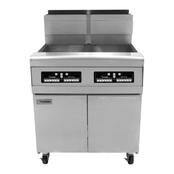
Performance Series
MJ40-MJ50
Gas Fryers
Installation, Operation and Maintenance Manual
This manual is updated as new information and models are released. Visit our website for the latest manual.
FOR YOUR SAFETY
Do Not Store or use gasoline
or other flammable vapors
and liquids in the vicinity of
this or any other appliance.
*8197397*
Part Number: FRY_IOM_8197397 09/2018
Original Instructions
Your Growth Is Our Goal
READ THE INSTRUCTIONS BEFORE USING THE FRYER.
Read these instructions for use carefully so as to
familiarize yourself with the appliance before
connecting it to its gas supply.
Keep these instructions for future reference.
CAUTION
NON-CE &
Advertisement

Related Manuals for Frymaster Performance MJ40


Summary of Contents for Frymaster Performance MJ40
- Page 1 Your Growth Is Our Goal Performance Series MJ40-MJ50 Gas Fryers Installation, Operation and Maintenance Manual This manual is updated as new information and models are released. Visit our website for the latest manual. CAUTION READ THE INSTRUCTIONS BEFORE USING THE FRYER. FOR YOUR SAFETY Read these instructions for use carefully so as to Do Not Store or use gasoline...
- Page 2 IF, DURING THE WARRANTY PERIOD, THE CUSTOMER USES A PART FOR THIS FRYMASTER FOODSERVICE EQUIPMENT OTHER THAN AN UNMODIFIED NEW OR RECYCLED PART PURCHASED DIRECTLY FROM FRYMASTER DEAN, OR ANY OF ITS AUTHORIZED SERVICERS, AND/OR THE PART BEING USED IS MODIFIED FROM ITS ORIGINAL CONFIGURATION, THIS WARRANTY WILL BE VOID.
- Page 3 NOTICE TO OWNERS OF UNITS EQUIPPED WITH COMPUTERS U.S. This device complies with Part 15 of the FCC rules. Operation is subject to the following two conditions: 1) This device may not cause harmful interference, and 2) This device must accept any interference received, including interference that may cause undesired operation.
- Page 4 WARNING If the electrical power supply cord is damaged, it must be replaced by a Frymaster Factory Authorized Servicer or a similarly qualified person in order to avoid a hazard. DANGER Adequate means must be provided to limit the movement of the appliance without depending upon the gas line connector and the quick-disconnect device or its associated piping to limit the appliance movement.
-
Page 5: Table Of Contents
Performance Series Gas Fryers Models MJ40 & MJ50 Installation and Operation Manual TABLE OF CONTENTS Page Chapter 1: Introduction Chapter 2: Installation Instructions Chapter 3: Operating Instructions Chapter 4: Filtration Instructions Chapter 5: Preventive Maintenance Chapter 6: Operator Troubleshooting... -
Page 6: Performance Series Gas Fryers Models Mj40 & Mj50
Service, and Parts Manual. Parts orders may be placed directly with your local FAS or distributor. A list of Frymaster Factory Authorized Servicers (FAS’s) is located on the Frymaster website at www.frymaster.com. If you do not have access to this list, contact the Frymaster Ser- vice Department at 1-800-551-8633 or 1-318-865-1711. - Page 7 Safety Information Before attempting to operate your unit, read the instructions in this manual thoroughly. Throughout this manual, you will find notations enclosed in double-bordered boxes similar to the ones that follow. CAUTION CAUTION boxes contain information about actions or conditions that may cause or result in a malfunction of your system.
- Page 8 Fryers having a MJ designation have no built-in filtration. Garland Model GF16FR and the Frymaster Model AGF14 are represented by Model MJ40. Fryers having a FMJ designation have a built-in filtration system under the two leftmost fryers. Those having a FMJ##0S designation have a built-in filtration system under the two leftmost stations and a holding station.
- Page 9 Installation, Operating, and Service Personnel Operating information for Frymaster equipment has been prepared for use by qualified and/or authorized personnel only, as defined in Section 1.7. All installation and service on Frymaster equipment must be performed by qualified, certified, licensed, and/or authorized installation or service personnel, as defined in Section 1.7.
- Page 10 Frymaster equipment. A list of Frymaster Factory Author- ized Servicers (FAS’s) is located on the Frymaster website at www.frymaster.com. Failure to use qualified service personnel will void the Frymaster warranty on your equipment.
-
Page 11: Chapter 2: Installation Instructions
General Installation Requirements Qualified, licensed, and/or authorized installation or service personnel, as defined in Section 1.7 of this manual, should perform all installation and service on Frymaster equipment. Conversion of this appliance from one type of gas to another should only be performed by qualified, licensed, and/or authorized installation or service personnel as defined in Section 1.7 of this manual. - Page 12 For U.S. installation, NFPA standard No. 96 states, "A minimum distance of 18 inches (450 mm) should be maintained between the flue outlet and the lower edge of the grease filter.” Frymaster recommends that the minimum distance be 24 inches (600 mm) from the flue outlet to the bottom edge of the filter when the appliance consumes more than 120,000 BTU per hour.
- Page 13 Installation shall be made with a gas connector that complies with national and local codes, and, where applicable, CE codes. Quick-Disconnect devices, if used, shall likewise comply with national, local, and, if applicable, CE codes. In the absence of local codes, installation must conform to the national Fuel Gas Code, ANSI Z223.1/NFPA 54 or the Natural Gas and Propane Installation code, CSA B149.1, as applicable including: The appliance and its individual shutoff valve must be disconnected form the gas supply...
- Page 14 Frymaster computers have been tested and found to comply with the limits for a Class A digital device, pursuant to Part 15 of the FCC rules. While these devices are verified as Class A devices, they have been shown to meet the Class B limits.
- Page 15 Dimensions The 50 in a single cabinet is 6.00 MJ50 (152) CORDSET available with an optional lower rear gas connection, which accommodates installations closer to the wall. The gas assembly, 108-5651, is INCHES (MM) available with an NPT-to-BSPT adapter, 813-0540. 46.86 (1190) 15.62...
- Page 16 Level fryers equipped with legs by screwing out the legs approximately 1 inch, and then adjust them so that the fryer is level and at the proper height in the exhaust hood. Frymaster recommends that the minimum distance from the flue outlet to the bottom edge of the filter be 24...
- Page 17 3. For fryers equipped with casters, there are no built-in leveling devices. The floor where the fryer is to be installed must be level. 4. Test the fryer electrical system: Verify correct voltage and connect per National codes and regulations. a.
- Page 18 7. Remove the cover of the EZSpark push-button battery powered ignitor and insert the AAA battery with the positive end towards the rear of the fryer (see illustration below). Replace the cover ensuring it is securely attached. Connection to Gas Line DANGER Before connecting new pipe to this appliance, the pipe must be blown out thoroughly to remove all foreign material.
- Page 19 Performance Series Atmospheric gas fryers have received the CE mark for the countries and gas Table 3: CE Approved Gas Categories categories indicated in Table 3 (right). Pressure Country Category (mbar) I2E+(S) G20/G25 20/25 I2 ELL G20/G25 DK-GR-IT I2 H G20/G25 20/25 II2Esi3P...
- Page 20 NOTE: Some fryers are configured for a rigid connection to the gas supply line. These units are connected to the gas supply line at the rear of the unit. When using thread compound, use very small amounts on male threads only. Use a pipe thread compound that is not affected by the chemical action of LP gases (Loctite PST567 sealant is one such compound).
- Page 21 Chapter 5. For units equipped with other types of controllers, refer to the appropriate section of the Frymaster Fryer Controllers User’s Manual, provided with your equipment for instructions on programming and operating your controller. Ensure Burner Targets Are Properly Spaced The top edge of the metal burner target should be ¾”...
- Page 22 DANGER Conversion of this appliance from one type of gas to another should only be performed by qualified, licensed, and authorized installation or service personnel, as defined in Section 1.7 of this manual. CE Gas Conversion Instructions 1. Between G20- and G25-type Natural Gas, adjust the gas pressure at the regulator. (Refer to the CE Standard Burner Manifold Gas Pressure Chart.) Do not change the orifice or pilot.
- Page 23 Non-CE Gas Conversion Instructions For fryers at elevations at or above 5,000 feet (1524 meters), call Frymaster Service (1-800- 551-8633) to determine the components appropriate for your configuration and altitude. Contact your local FAS to order the components and arrange for installation. For fryers below 5000 feet (1524 meters), see the kits listed below for conversion.
-
Page 24: Chapter 3: Operating Instructions
PERFORMANCE SERIES GAS FRYERS MODELS MJ40 & MJ50 CHAPTER 3: OPERATING INSTRUCTIONS Start-Up Procedure DANGER Never operate this appliance with an empty frypot. The frypot must be filled with water or cooking oil/shortening before lighting the burners. Failure to do so will damage the frypot and may cause a fire. - Page 25 ACCESSING THE PILOT In full-vat units, the pilot is mounted on the left side of the burner manifold and is accessed through an opening in the front frypot insulation. In dual-vat units, there is a pilot on both the left and the right halves of the burner manifold. LIGHTING THE PILOT ON FRYERS WITH STANDARD HONEYWELL GAS VALVES 1.
- Page 26 2. Press and hold the pilot (white) button, then repeatedly press the ignitor button until the pilot lights. 3. Failure to hold the button in long enough will cause the pilot to go out when the button is released. If the pilot goes out when the button is released, wait at least 5 minutes then repeat this step.
- Page 27 To ensure that the frypot is free of any contamination resulting from its manufacture, shipping, and handling during installation, the frypot must be boiled out before first use. Frymaster recommends boiling out the frypot each time the oil or shortening is changed.
- Page 28 Controller Operation and Programming Fryers in the Performance Series can be equipped with Computer Magic III.5 (CM III.5) controller, Digital Controllers, or Thermostat Controllers. Instructions for using each type are included in the separate Frymaster Fryer Controllers User’s Manual provided with your equipment.
-
Page 29: Chapter 4: Filtration Instructions
If you intend to reuse the oil or shortening, Frymaster recommends that a Frymaster filter cone holder and filter cone be used when a filter machine is not available. If you are using a... - Page 30 Frymaster filter cone holder, be sure that the cone holder rests securely on the metal container. 3. Open the drain valve slowly to avoid splattering. If the drain valve becomes clogged with food particles, use the Fryer’s Friend (poker-like tool) to clear the blockage.
- Page 31 4.2.1 Preparation for Use with Filter Paper or Filter Pad 1. Pull the filter pan out from the cabinet and remove the crumb screen, hold- down ring, and filter screen. The filter pan is equipped with rollers in rails, much like a kitchen drawer. The pan may be removed for cleaning or to gain access to interior components by lifting the front of the pan to disengage...
- Page 32 Place the filter screen in the bottom of the filter pan. 4. Lay a sheet of filter paper over the screen, overlapping on all sides, or, if using a filter pad, lay the pad over the screen. Lay a sheet of filter paper or a filter pad over the screen.
- Page 33 4.2.2 Preparation for Use with the Magnesol Filter Assembly 1. Pull the filter pan out from the cabinet and remove the crumb screen and Magnesol filter assembly. The filter pan is equipped with rollers in rails, much like a kitchen drawer. The pan may be removed for cleaning or to gain access to interior components by lifting the front of the pan to disengage...
- Page 34 NEVER attempt to drain cooking oil or shortening from the fryer with the burners lit! Doing so will cause irreparable damage to the frypot and may cause a flash fire. Doing so will also void the Frymaster warranty. 1. Turn the fryer power OFF. Drain ONE of the frypots into the filter pan.
- Page 35 DO NOT hammer on the drain valve with the cleanout rod or other objects. Damage to the ball inside will result in leaks and will void the Frymaster warranty. 2. After the cooking oil has drained from...
- Page 36 WARNING The filter pump is equipped with a manual reset switch in case the filter motor overheats or an electrical fault occurs. If this switch trips, turn off power to the filter system and allow the pump motor to cool 20 minutes before attempting to reset the switch (see photo below).
- Page 37 Disassembly and Reassembly of the Magnesol Filter Dissassembly 1. Grasp the frame with your thumbs on the handles at the corner of the assembly and pull outward in opposite directions to separate the frame at the corner. Continue to open the frame (it will pivot at the opposite corner) until the outer screens and grid can be removed from the frame.
- Page 38 Frymaster recommends the use of the Frymaster Shortening Disposal Unit (SDU). NOTE: The filter pan lid must be removed from the fryer to allow the SDU to fit under the drain. To remove the lid, lift up on the front edge and pull it straight out of the cabinet.
- Page 39 4.5.1 Disposing of Oil with Optional Rear Discharge Turn the handle to the left to return oil from the filter pan to the frypot. Turn it to the right to discharge the oil to the disposal system. 1. Ensure the filter pan is clean and prepared for filtration. Prepare the filter pan if necessary. DO NOT discharge oil through a dirty or incomplete filter pan.
-
Page 40: Chapter 5: Preventive Maintenance
PERFORMANCE SERIES GAS FRYERS MODELS MJ40 & MJ50 CHAPTER 5: PREVENTATIVE MAINTENANCE Fryer Preventive Maintenance Checks and Services DAILY CHECKS AND SERVICES Inspect Fryer and Accessories for Damage Look for loose or frayed wires and cords, leaks, foreign material in frypot or inside cabinet, and any other indications that the fryer and accessories are not ready and safe for operation. - Page 41 If your fryer is not equipped with the built-in filtration system, the cooking oil or shortening must be drained into another suitable container. For safe, convenient draining and disposal of used cooking oil or shortening, Frymaster recommends the use of our shortening disposal unit (SDU). The SDU is available through your local distributor.
- Page 42 4. Insert a good-grade thermometer or pyrometer probe into the oil/shortening, with the end touching the fryer temperature probe. 5. When the burner starts for the fourth time, the thermometer/pyrometer reading should be within ± 5ºF (2ºC) of the temperature knob setting. If not, calibrate as follows: a.
- Page 43 3. Press the switch twice to display the set point. 4. Note the temperature on the thermometer or pyrometer. All three readings should be within ±5°F (2°C) of each other. If not, contact a Factory Authorized Servicer for assistance. Clean Gas Valve Vent Tube 1.
- Page 44 ANNUAL/PERIODIC SYSTEM INSPECTION This appliance should be inspected and adjusted periodically by qualified service personnel as part of a regular kitchen maintenance program. Frymaster recommends that this appliance be inspected at least annually by a Factory Authorized Servicer as follows: Fryer ...
- Page 45 Verify that all O-rings and seals (including those on the on quick-disconnect fittings) are present and in good condition. Replace O-rings and seals if worn or damaged. Check filtration system integrity as follows: With the filter pan empty, place each oil return handle, one at a time, in the ON position. Verify that the pump activates and that bubbles appear in the cooking oil/shortening of the associated frypot.
-
Page 46: Chapter 6: Operator Troubleshooting
If you are in doubt as to the proper action to take, do not hesitate to call the Frymaster Technical Service Department or your local Frymaster Factory Authorized Servicer for assistance. - Page 47 6.2 Troubleshooting Fryers with Solid State (Analog), Digital or CM III.5 Controllers PROBLEM PROBABLE CAUSES CORRECTIVE ACTION A. Light pilot per instructions in A. Pilot not lit. Chapter 3 of this manual. B. Verify that drain valve is fully B. Drain valve open. closed.
- Page 48 PROBLEM PROBABLE CAUSES CORRECTIVE ACTION A. Disconnect unit from electrical A. Temporary controller power, wait at least one minute, malfunction caused by voltage reconnect unit to the power surge. supply and turn controller on. CM III.5 will not go B. If available, substitute controller into programming known to be good for suspect mode.
- Page 49 Troubleshooting Fryers with Thermostat Controls PROBLEM Probable Causes Corrective Action A. Light pilot per instructions in A. Pilot is not lit. Chapter 3 of this manual. B. Drain valve not fully closed. B. Verify drain valve is fully closed. C. Verify that unit is correctly C.
- Page 50 Troubleshooting the Built-In Filtration System PROBLEM PROBABLE CAUSES CORRECTIVE ACTION A. Thermal overload switch has A. If the pump runs normally after tripped on an overheated motor. resetting the thermal overload switch, the pump was overheated. Test: If the pump stopped suddenly during the filtering Always filter with the cooking process, especially if after several...
- Page 51 PROBLEM PROBABLE CAUSES CORRECTIVE ACTION A. To properly filter, the oil or shortening should be at or near 350°F (177°C). At temperatures lower than this, the oil or shortening becomes too thick to pass through the filter medium A. Cooking oil/shortening is too easily, resulting in much slower cold for filtering.
- Page 52 FRYMASTER 8700 LINE AVENUE, SHREVEPORT, LA 71106‐6800 800‐551‐8633 318‐865‐1711 WWW.FRYMASTER.COM EMAIL: FRYSERVICE@WELBILT.COM *8197423* WWW.WELBILT.COM Welbilt provides the world’s top chefs, and premier chain operators or growing independents with industry leading equipment and solutions. Our cutting‐edge designs and lean manufacturing tactics are powered by deep knowledge, operator insights, and culinary expertise. All of our products are backed by KitchenCare® – our aftermarket, repair, and parts service. CLEVELAND DELFIELD® FRYMASTER® KOLPAK® MANITOWOC® MERRYCHEF® CONVOTHERM® FITKITCHEN™ GARLAND LINCOLN MERCO® MULTIPLEX® ©2018 Welbilt Inc. except where explicitly stated otherwise. All rights reserved. Continuing product improvement may necessitate change of specifications without notice.
Need help?
Do you have a question about the Performance MJ40 and is the answer not in the manual?
Questions and answers