Table of Contents
Advertisement
Quick Links
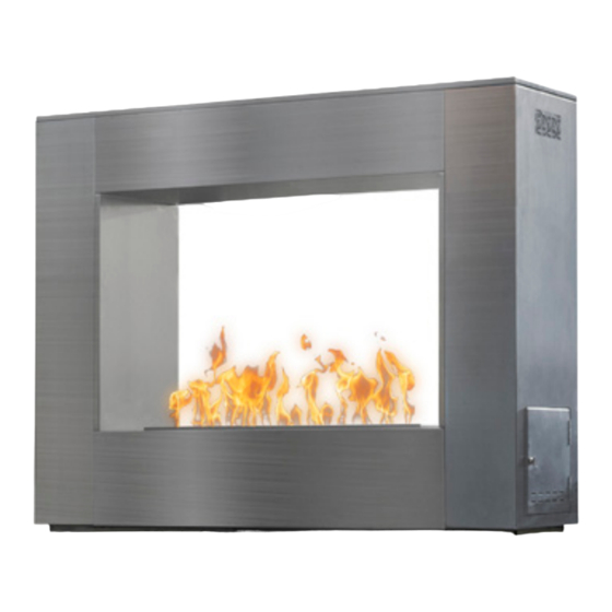
THE WILLIAMS FIREPLACE
THE WILLIAMS
READY TO FINISH
TFL-WILL72RTF
TFL-WILL84RTF
TFL-WILL72RTFSC
TFL-WILL96RTF
TFL-WILL84RTFSC
TFL-WILL96RTFSC
Thank you for purchasing
the Williams Fireplace.
OWNER'S MANUAL
OWNER'S MANUAL
THE WILLIAMS
THE WILLIAMS
READY TO FINISH
STAINLESS STEEL
WITH SCUPPER
Save these instructions for future use. If
you are assembling this unit for someone
else, give this manual to him or her to
read and save for the future.
If you have any questions,
please contact customer service
PHONE: (909) 460-5579
EMAIL: support@theoutdoorplus.com
ADDRESS: 701 S Dupont Ave. Ontario, CA 91761 U.S.A.
WEBSITE: www.theoutdoorplus.com
THE WILLIAMS
CORTEN STEEL
TFL-WILL72SS
TFL-WILL72CS
TFL-WILL84SS
TFL-WILL84CS
TFL-WILL96SS
TFL-WILL96CS
THE WILLIAMS
POWDER COAT
TFL-WILL72PC
TFL-WILL84PC
TFL-WILL96PC
Advertisement
Table of Contents

Related Manuals for Outdoor Plus WILLIAMS TFL-WILL72RTF

Summary of Contents for Outdoor Plus WILLIAMS TFL-WILL72RTF
- Page 1 PHONE: (909) 460-5579 EMAIL: support@theoutdoorplus.com ADDRESS: 701 S Dupont Ave. Ontario, CA 91761 U.S.A. WEBSITE: www.theoutdoorplus.com THE WILLIAMS FIREPLACE OWNER’S MANUAL THE WILLIAMS THE WILLIAMS THE WILLIAMS THE WILLIAMS THE WILLIAMS READY TO FINISH READY TO FINISH STAINLESS STEEL CORTEN STEEL POWDER COAT WITH SCUPPER TFL-WILL72RTF...
- Page 2 THE WILLIAMS FIREPLACE INSTALLATION & OPERATION DANGER FIRE OR EXPLOSION HAZARD If you smell gas: - Shut off gas to the appliance. - Extinguish any open flame. - If odor continues, leave the area immediately. - After leaving the area, call your gas supplier or fire depatment. Failure to follow these instructions could result in fire or explosion, which could cause property damage, personal injury, or death.
- Page 3 SAFETY INFORMATION The installation of this unit must adhere to local codes or either the National Fuel Gas Code, ANSI Z223. 1/NFPA54, OR CAN/CGA-B149.1, National Gas and Propane Installation Code. • THIS UNIT IS INTENDED FOR OUTDOOR USE ONLY! This product shall be used outdoors, in a ventilated space and shall not be used in any enclosed area.
- Page 4 SAFETY INFORMATION • Combustible material should not be within 72 inches of the top of the unit, or within 48 inches around the entire unit. • Keep the appliance area clear and free from combustible material, gasoline and other flammable vapors and liquids.
- Page 5 DANGER FLAMMABLE GAS UNDER PRESSURE. LEAKING LP-GAS MAY CAUSE A FIRE OR EXPLOSION IF IGNITED CAUSING SERIOUS BODILY INJURYOR DEATH. CONTACT LP GAS SUPPLIER FOR REPAIRS, OR DISPOSAL OF THIS CYLINDER OR UNUSED LP-GAS. WARNING FOR OUTDOOR USE ONLY.* DO NOTUSE OR STORE CYLINDER IN A BUILDING, GARAGE OR ENCLOSED AREA.
- Page 6 WARNINGS THIS SECTION OUTLINES WARNING ASSOCIATED WITH INSTALLATION, USE, AND OPERATION. WARNING: FOR OUTDOOR USE ONLY Installation and service must be performed by a qualified installer, service agency, or the gas supplier. » Do not store or use gasoline or other flammable vapors and liquids, In the vicinity of this or any other appliance.
- Page 7 Canada by WETT (Wood Energy Technical Training). Installer must follow all instructions carefully to ensure proper performance and safety. » The Outdoor Plus Company, Inc. is not responsible for your actions. » Product is not intended to be a starter for wood or any other combustibles.
-
Page 8: Table Of Contents
TABLE OF CONTENTS DIRECTORY OF PAGES & SECTIONS SECTION 1 | COMPONENTS OVERVIEW..................9 SECTION 4 | OPERATION SEQUENCE..................11 SECTION 5 | SELECTING THE LOCATION..................12 SECTION 6 | ENCLOSURE CONSTRUCTION................13 SECTION 7 | PRE-PLANNING CHECKLIST..................14 SECTION 8 | INSTALLATION INSTRUCTIONS................15 SECTION 10 | CONNECTING YOUR GAS LINE................22 SECTION 11 | HOW TO TURN ON YOUR MATCH LIT SYSTEM...........24 SECTION 12 | HOW TO TURN ON YOUR MATCH LIT WITH FLAME SENSE......25 SECTION 13 | HOW TO TURN ON YOUR FLAME SENSE WITH SPARK IGNITION....26... -
Page 9: Section 1 | Components Overview
COMPONENTS OVERVIEW THIS SECTION OUTLINES THE FEATURES OF THE PLUG & PLAY TO LOW VOLTAGE PANS & BURNERS Installation must conform with local codes or, in the absence of local codes, with the National Fuel Gas Code, ANSI Z223.1 / NFPA 54, or International Fuel Gas Code. The appliance when installed, must be electrically grounded in accordance with local codes, or in the ab- sence of local codes, with the National Electrical Code, ANSI/NFPA 70;... - Page 10 175° Fahrenheit. To keep the unit cool, proper ventilation and a heat shield must be provided. The Outdoor Plus Recommends a Stainless Steel Whistle-Free Flex Hose to eliminate the noise. PILOT ASSEMBLY CONNECTIONS We pre-assemble the pilot on top of the burner pan and in that configuration, the pilot line, thermocouple and igniter lead should be lowered through a hole in the pan prior to connecting to the control box.
-
Page 11: Section 4 | Operation Sequence
OPERATION SEQUENCE THIS SECTION DEMONSTRATES THE OPERATION SEQUENCE OF OUR PLUG & PLAY TO LOW VOLTAGE PANS & BURNERS. OPERATIONS When powdered, indicating a call for heat, the unit will wait for Pre- the ignition sequence. If a flame is not detected during the Trail-For-Ig- Purge time. -
Page 12: Section 5 | Selecting The Location
SELECTING THE LOCATION THIS SECTION DEMONSTRATEWS LOCATION REQUIREMENTS & WARNINGS WARNING: All fireplaces, match lit kits, spark ignition, safety pilot and Electronic Ignition Components are designed and intended for outdoor use only. » All fireplaces must have a gas shutoff on the outside of the exterior of the fireplace to allow for emergency shut off and maintenance. -
Page 13: Section 6 | Enclosure Construction
▪ The Outdoor Plus recommends that the pan lip is recessed on trough (linear). The Outdoor Plus cannot guarantee the lip on all of our products will be perfectly flat and will not warp due to heat. -
Page 14: Section 7 | Pre-Planning Checklist
PRE-PLANNING CHECKLIST THIS SECTION DEMONSTRATES THE PROPER INSTALLATION AND TESTING OF THE PLUG & PLAY TO LOW VOLTAGE SYSTEMS. TO ENSURE PROPER INSTALLATION PLEASE USE THIS PRE-PLANNING CHECKLIST: Recommended Tools: General Plumbing Tools (Pipe Wrench, Crescent Wrench, Pipe Cutters, etc.) Manometer (To test static &... -
Page 15: Section 8 | Installation Instructions
INSTALLATION INSTRUCTIONS THIS SECTION DEMONSTRATES THE PROPER INSTALLATION AND TESTING OF THE PLUG & PLAY TO LOW VOLTAGE SYSTEMS. STEP 1 | SELECTING A LOCATION Section 5 » Please see on Selecting a location for instructions. STEP 2 | VENTILATION & ENCLOSURE CONSTRUCTION »... - Page 16 INSTALLATION INSTRUCTIONS CONT’D THIS SECTION DEMONSTRATES THE PROPER INSTALLATION AND TESTING OF THE PLUG & PLAY TO LOW VOLTAGE SYSTEMS. STEP 7 | OPERATION INSTRUCTIONS see Section 11 ▪ Please on Operation Instructions, this section outlines how to operate your Plug & Play to Low Voltage Pans &...
- Page 17 INSTALLATION INSTRUCTIONS [LOW VOLTAGE] CONT’D THIS SECTION DEMONSTRATES THE PROPER INSTALLATION AND TESTING OF THE PLUG & PLAY TO LOW VOLTAGE SYSTEMS. Figure 2.1 | Using a Pool Controller with 110V Accessories & 12V-14V Control Panel POOL CONTROLLER/ SMART HOME SYSTEM 12V-14V CONTROL PANEL Burner...
- Page 18 INSTALLATION INSTRUCTIONS [PLUG & PLAY] CONT’D THIS SECTION DEMONSTRATES THE PROPER INSTALLATION AND TESTING OF THE PLUG & PLAY TO LOW VOLTAGE SYSTEMS. Figure 3.1 | Using an Emergency Stop & Dial Timer Burner Pan Pilot Burner Assembly Burner 110V OUTLET EMERGENCY STOP (WITH OUTDOOR COVER) BUTTON ON 110VAC...
- Page 19 INSTALLATION INSTRUCTIONS [PLUG & PLAY] CONT’D THIS SECTION DEMONSTRATES THE PROPER INSTALLATION AND TESTING OF THE PLUG & PLAY TO LOW VOLTAGE SYSTEMS. Figure 3.3 | Using an Emergency Stop & Dial Timer EMERGENCY STOP DIAL TIMER BUTTON ON 110VAC 110VAC ALWAYS PLACE FIRST Burner...
- Page 20 INSTALLATION INSTRUCTIONS - THE WILLAIMS WITH SCUPPER THIS SECTION DEMONSTRATES THE PROPER INSTALLATION AND TESTING OF THE WILLIAMS WITH SCUPPER FIGURE 3.2 | Using a Standard Light Switch Scupper POOL CONTROLLER/ SMART HOME SYSTEM 12V-14V CONTROL PANEL Burner Burner Pan OPTIONAL Pilot Burner Assembly 110V ACCESSORIES...
- Page 21 OPERATION & USAGE THIS SECTION EXPLAINS HOW TO OPERATE THE FIRE FEATURE Congratulations on getting your new fire feature installed! Let’s get started with how to operate and use your Williams Fire Place. Your fire feature should have one of the following methods to turn on and off the fire feature: Match Lit Ignition System »...
-
Page 22: Section 10 | Connecting Your Gas Line
CONNECTING YOUR GAS LINE THIS SECTION EXPLAINS HOW TO OPERATE THE FIRE FEATURE STEP 1 PLACE THE FIREPLACE IN A DESIRED LOCATION THE WILLIAMS FIREPLACE ARE DESIGNED FOR OUTDOOR USE ONLY! » Never place this appliance in a building, garage, or any other enclosed room or under a sealed overhead structure, or in any type of enclosed area such as a garage, shed, or breezeway. - Page 23 CONNECTING YOUR GAS LINE THIS SECTION EXPLAINS HOW TO OPERATE THE FIRE FEATURE STEP 2 CONNECT THE GAS LINE LOCATION OF THE GAS » This fireplace works for both Liquid Propane and Natural Gas Installation. You fireplace comes pre-plumbed all you need to do is connect the gas line to the appropiate gas inlet. STEP 2A STEP 2B CONNECTING LIQUID PROPANE...
-
Page 24: Section 11 | How To Turn On Your Match Lit System
HOW TO TURN ON YOUR MATCH LIT SYSTEM THIS SECTIONS EXPLAINS HOW TO TURN ON YOUR MATCH LIT SYSTEM STEP 1 STEP 2 Place Your Key Valve Have a Light Ready » Place the Key Valve on the Gas Valve. Place the Key Valve on »... -
Page 25: Section 12 | How To Turn On Your Match Lit With Flame Sense
HOW TO TURN ON YOUR MATCH LIT WITH FLAME SENSE THIS SECTIONS EXPLAINS HOW TO TURN ON YOUR MATCH LIT WITH FLAME SENSE STEP 1 STEP 2 STEP 3 Push the Knob In Have your Lighter Ready. Turn the knob on. »... -
Page 26: Section 13 | How To Turn On Your Flame Sense With Spark Ignition
HOW TO TURN ON YOUR FLAME SENSE WITH SPARK IGNITION THIS SECTIONS EXPLAINS HOW TO TURN ON YOUR FLAME SENSE WITH SPARK IGNITION STEP 1A STEP 1B STEP 1C PUT ON THE BATTERY PUT ON THE BATTERY PUT ON THE BATTERY UNDO THE BATTERY KNOB FLIP THE BATTERY TO ITS CORRECT POSITION UNDO THE BATTERY KNOB... - Page 27 HOW TO TURN ON YOUR FLAME SENSE WITH SPARK IGNITION THIS SECTIONS EXPLAINS HOW TO TURN ON YOUR FLAME SENSE WITH SPARK IGNITION STEP 3A STEP 3B STEP 3C TURNING OFF TURNING OFF TURNING OFF PLACE THE KNOB ON (PILOT LIGHT) TURNING OFF COMPLETELY OFF »...
-
Page 28: Section 14 | How To Turn On Your Low Voltage Electronic Ignition System
HOW TO TURN ON YOUR LOW VOLTAGE ELECTRONIC IGNITION THIS SECTIONS EXPLAINS HOW TO TURN ON YOUR LOW VOLTAGE ELECTRONIC IGNITION STEP 1A STEP 1B STEP 1C CONNECTING LOW VOLTAGE CONNECTING LOW VOLTAGE CONNECTING LOW VOLTAGE » Your Low Voltage should come connected. »... - Page 29 HOW TO TURN ON YOUR LOW VOLTAGE ELECTRONIC IGNITION THIS SECTIONS EXPLAINS HOW TO TURN ON YOUR LOW VOLTAGE ELECTONIC IGNITION LOW VOLTAGE ELECTONIC IGNITION THEOUTDOORPLUS.COM | +1 (909) 460-5579 | SUPPORT@THEOUTDOORPLUS.COM...
-
Page 30: Section 15 | How To Turn On Your Plug & Play Ready System
HOW TO TURN ON YOUR PLUG & PLAY IGNITION SYSTEM THIS SECTIONS EXPLAINS HOW TO TURN ON YOUR PLUG & PLAY READY IGNITION SYSTEM STEP 1A STEP 1B STEP 1C TURNING ON TURNING ON TURNING ON CONNECT THE PLUG - 1A CONNECT THE PLUG - 1B YOUR SMART DEVICE »... -
Page 31: Section 16 | Troubleshooting
TROUBLESHOOTING THIS SECTION DEMONSTRATES POTENTIAL ISSUES & COUNTERMEASURES TO REPAIR YOUR UNIT SEQUENCE OF FAULT CHECK RESULT ACTION(S) OPERATION Check for 14V at Make sure transformer is Transformer powered. If so, replace transformer. No or Low Voltage Power ON No Function / No LED Indication Check wiring for continuity, replace if broken. - Page 32 TROUBLESHOOTING CONT’D THIS SECTION DEMONSTRATES POTENTIAL ISSUES & COUNTERMEASURES TO REPAIR YOUR UNIT THE ELECTRONIC IGNITION VALVE IS INSTALLED BUT WHEN TURNED ON NOTHING HAPPENS: The most common cause is an electrical wiring or power issue. Inspect all electrical connections carefully to confirm all wires from the transformer to the fire feature are connected properly.
- Page 33 TROUBLESHOOTING CONT’D THIS SECTION DEMONSTRATES POTENTIAL ISSUES & COUNTERMEASURES TO REPAIR YOUR UNIT » CAUTION: Turn off the gas supply before proceeding. » Utilizing clamp on ammeter, clamp the ammeter around one of the wires providing power to the Electronic Ignition Valve. »...
-
Page 34: Section 17 | Maintenance
(see your local The Outdoor Plus Disconnected cylinders must have threaded dealer for details). valve plugs tightly installed and must not... - Page 35 » Do NOT perform the maintenance until surfaces of the fire feature are cool to the touch, The Outdoor Plus recommends leaving the fireplace off for at least 1 hour prior to servicing. » Remove any debris on or around the fire feature such as spider webs, dirt, etc.
-
Page 36: Section 18 | Replaccement Parts
REPLACEMENT PARTS THIS SECTION SHOWS REPLACEMENT PARTS YOU MAY ORDER TO REPAIR THE UNIT. PILOT IGNITER GLOW PLUG THERMOCOUPLE PILOT IGNITER REPLACEMENT COVER TOP-500PI REPLACEMENT TOP-PITC TOP-PIC TOP-PIGP TURN KEY FOR GAS VALVES STAINLESS STEEL Call for Part No. Many Variations WHISTLE FREE HOSE Call for Part No. -
Page 37: Section 19 | Clearance From Combustibles
CLEARANCE FROM COMBUSTIBLES THIS SECTION OUTLINES THE CLEARANCE FROM COMBUSTIBLES REQUIREMENTS FOR SAFE OPERATION Clearance for units with up to 65K BTUs - For Outdoor Use Only Flooring All fireplaces and fire features must be installed on non-combustible flooring. If the fire feature is installed on a combustible floor, such as wood decking, a non combustible floor paneling MUST be properly installed underneath. - Page 38 CLEARANCE FROM COMBUSTIBLES THIS SECTION OUTLINES THE CLEARANCE FROM COMBUSTIBLES REQUIREMENTS FOR SAFE OPERATION Clearance for units with up to 65K BTUs - For Outdoor Use Only Flooring All fireplaces and fire features must be installed on non-combustible flooring. If the fire feature is installed on a combustible floor, such as wood decking, a non combustible floor paneling MUST be properly installed underneath.
-
Page 39: Section 16 | Warranty Information
WARRANTY INFORMATION THIS SECTION OUTLINES THE WARRANTY OFFERED BY THE OUTDOOR PLUS The Outdoor Plus Company (TOP) warranties its products » TOP is not responsible for local codes and will not accept against manufacturing defects that prevent safe and prop-... - Page 40 701 S Dupont Ave Ontario, CA 91761 All products proudly made in the U.S.A...
Need help?
Do you have a question about the WILLIAMS TFL-WILL72RTF and is the answer not in the manual?
Questions and answers