Advertisement
Quick Links
THE WILLIAMS FIREPLACE
THE WILLIAMS
READY TO FINISH
TFL-WILL72RTF
TFL-WILL84RTF
TFL-WILL72RTFSC
TFL-WILL96RTF
TFL-WILL84RTFSC
TFL-WILL96RTFSC
Thank you for purchasing
he Williams Fireplace.
OWNER'S MANUAL
OWNER'S MANUAL
THE WILLIAMS
THE WILLIAMS
READY TO FINISH
STAINLESS STEEL
WITH SCUPPER
Save these instructions for future use. If
you are assembling this unit for someone
else,
If you have any questions,
please contact customer service:
Support@theoutdoorplus.com
(909) 460-5579
PHONE: (909) 460-5579
EMAIL: support@theoutdoorplus.com
ADDRESS: 701 S Dupont Ave Ontario, CA 91761 U.S.A.
WEBSITE: www.theoutdoorplus.com
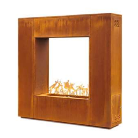
THE WILLIAMS
CORTEN STEEL
TFL-WILL72SS
TFL-WILL72CS
TFL-WILL84SS
TFL-WILL84CS
TFL-WILL96SS
TFL-WILL96CS
THE WILLIAMS
POWDER COAT
TFL-WILL72PC
TFL-WILL84PC
TFL-WILL96PC
.
Advertisement

Related Manuals for Outdoor Plus WILLIAMS

Summary of Contents for Outdoor Plus WILLIAMS
- Page 1 PHONE: (909) 460-5579 EMAIL: support@theoutdoorplus.com ADDRESS: 701 S Dupont Ave Ontario, CA 91761 U.S.A. WEBSITE: www.theoutdoorplus.com THE WILLIAMS FIREPLACE OWNER’S MANUAL THE WILLIAMS THE WILLIAMS THE WILLIAMS THE WILLIAMS THE WILLIAMS READY TO FINISH READY TO FINISH STAINLESS STEEL CORTEN STEEL...
- Page 2 THE WILLIAMS FIREPLACE INSTALLATION & OPERATION DANGER FIRE OR EXPLOSION HAZARD If you smell gas: - Shut off gas to the appliance. - If odor continues, leave the area immediately. which could cause property damage, personal injury, or death. WARNING the vicinity of this or any other applianc WARNING: For Outdoor Use Only.
- Page 3 SAFETY INFORMATION The installation of this unit must adhere to local codes or either the National Fuel Gas Code, ANSI Z223. 1/NFPA54, OR CAN/CGA-B149.1, National Gas and Propane Installation Code. • THIS UNIT IS INTENDED FOR OUTDOOR USE ONLY! This product shall be used outdoors, in a ventilated space and shall not be used in any enclosed area.
- Page 4 SAFETY INFORMATION • Combustible material should not be within 72 inches of the top of the unit, or within 48 inches around the entire unit. vapors and liquids. • Do not add water into the unit. technician to inspect the appliance and replace any part of the control system and any gas control that has been under water.
- Page 5 DANGER FLAMMABLE GAS UNDER PRESSURE. LEAKING LP-GAS MAY CAUSE A FIRE OR EXPLOSION IF IGNITED CAUSING SERIOUS BODILY INJURYOR DEATH. CONTACT LP GAS SUPPLIER FOR REPAIRS, OR DISPOSAL OF THIS CYLINDER OR UNUSED LP-GAS. WARNING FOR OUTDOOR USE ONLY.* DO NOTUSE OR STORE CYLINDER IN A BUILDING, GARAGE OR ENCLOSED AREA.
- Page 8 TABLE OF CONTENTS DIRECTORY OF PAGES & SECTIONS SECTION 1 COMPONENTS OVERVIEW ..................9 SECTION 2 OPERATION SEQUENCE ..................11 SECTION 3 SELECTING THE LOCATION ..................12 SECTION 41 ENCLOSURE CONSTRUCTION ................13 SECTION 5 PRE-PLANNING CHECKLIST .................. 14 SECTION 6 INSTALLATION INSTRUCTIONS ................
- Page 11 POWER INDICATION CONTINUOUSLY START UP BLINKING (STEADY LIGHT) (THERMOCOUPLE TOO HOT OR MOTH- ER BOARD IS BAD) SOURCE SOLUTION SOLUTION BAD BOARD SEND FOR REPAIR SOURCE SOLUTION SOLUTION GLOW PLUG BAD GLOW PLUG REPLACE GLOW PLUG INDICATION SOLUTION NO/SOLUTION BAD GAS PRESSURE CONTINUOUSLY BLINKING VALVE OPEN...
- Page 12 SELECTING THE LOCATION THIS SECTION DEMONSTRATES LOCATION REQUIREMENTS & WARNINGS WARNING: All fireplaces, match lit kits, spark ignition, safety pilot and Electronic Ignition Components are designed and intended for outdoor use only. All fireplaces must have a gas shutoff on the outside of the exterior of the fireplace to allow for »...
- Page 14 PRE-PLANNING CHECKLIST THIS SECTION DEMONSTRATES THE PR OPER INSTALLATION AND TESTING OF THE PLUG & PLAY AND L OW VOLTAGE SYSTEMS. TO ENSURE PROPER INSTALLATION PLEASE USE THIS PRE-PLANNING CHECKLIST: □ Recommended Tools: General Plumbing Tools (Pipe Wrench, Crescent Wrench, Pipe Cutters, etc.) □...
- Page 16 INSTALLATION INSTRUCTIONS CONT'D THIS SECTION DEMONSTRA TES THE PROP ER INSTALLA TION AND TESTING OF THE PLUG & PLA Y AND LOW VOLTAGE SYSTEMS. STEP 71 OPERATION INSTRUCTIONS Please see Page 24 on Operation Instructions, this section outlines how to operate your Plug & Play to ■...
- Page 17 Figure 2.1 | Using an Automated Pool Controller with 110V Accessories & 30V DC Control Panel...
- Page 20 Figure 3.5 | Using an Automated Pool Controller with 110V Accessories & 30V DC Control Panel Figure 3.6 | Using an Automated Pool Controller with a 30V DC Control Panel...
- Page 22 SIDES AND BACK 48 inches (122 cm) 96 inches (244 cm) measured from side measured from hearth...
- Page 31 SEQUENCE OF FAULT CHECK RESULT ACTION(S) OPERATION Check for 14V at Make sure transformer is Transformer powered. If so, replace transformer. No or Low Voltage Power ON Check wiring for continuity, replace if broken. Check for 14V at Control Box No or Low Voltage minimum (smaller number is bigger wire) Replace with larger wire or shorten length.
- Page 35 THERMOCOUPLE GLOW PLUG PILOT LIGHT ORIFICE GAS LINE VISUALLY INSPECT THE PILOT...
Need help?
Do you have a question about the WILLIAMS and is the answer not in the manual?
Questions and answers