Cognex In-Sight 3800 Series Reference Manual
Hide thumbs
Also See for In-Sight 3800 Series:
- Reference manual (54 pages) ,
- Quick reference manual (56 pages)
Table of Contents
Advertisement
Advertisement
Table of Contents

Related Manuals for Cognex In-Sight 3800 Series


Summary of Contents for Cognex In-Sight 3800 Series
- Page 1 ® In-Sight 3800 Series Reference Manual 2023 March 17 Revision: 23.1.0.117...
-
Page 2: Legal Notices
Copyright © 2023. Cognex Corporation. All Rights Reserved. Portions of the hardware and software provided by Cognex may be covered by one or more U.S. and foreign patents, as well as pending U.S. and foreign patents listed on the Cognex web site at: cognex.com/patents. -
Page 3: Precautions
Precautions Precautions To reduce the risk of injury or equipment damage, observe the following precautions when you install the Cognex product: The safety of any system incorporating this product is the responsibility of the assembler of the system. Do not install Cognex products where they are exposed to environmental hazards such as excessive heat, dust, moisture, humidity, impact, vibration, corrosive substances, flammable substances, or static electricity. -
Page 4: Symbols
Symbols Symbols The following symbols indicate safety precautions and supplemental information: WARNING: This symbol indicates a hazard that could cause death, serious personal injury or electrical shock. CAUTION: This symbol indicates a hazard that could result in property damage. Note: This symbol indicates additional information about a subject. Tip: This symbol indicates suggestions and shortcuts that might not otherwise be apparent. -
Page 5: Table Of Contents
Connecting the Power and I/O Breakout Cable Using Your In-Sight Vision System Installing In-Sight Vision Suite Trigger Types External Triggers Supported Protocols Specifications In-Sight 3800 Series Vision System In-Sight 3800 Series Vision System Image Sensor LED Wavelengths Acquisition Trigger Input High-Speed Outputs... - Page 6 Table of Contents Ethernet Cable External Light Connector Breakout Cable Cleaning and Maintenance Clean the Housing Clean the Vision System Image Sensor Window Clean the Vision System Lens Cover Regulations and Conformity 中 国 大陆 RoHS (Information for China RoHS Compliance) For European Community Users...
-
Page 7: Getting Started
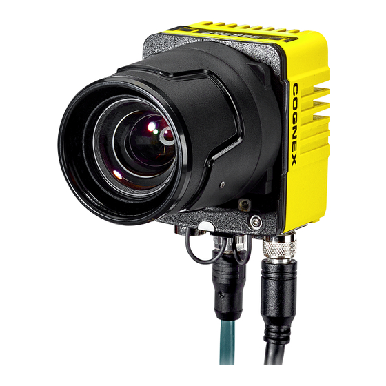
This section provides general information about the In-Sight 3800 series vision system and the accessories and systems. About the In-Sight 3800 Series The In-Sight 3800 series is an advanced vision system that provides high speed, high resolution, and high flexibility in a powerful yet easy-to-use solution for inspection automation. -
Page 8: Accessories
Getting Started Accessories You can purchase the following components separately. For a list of options and accessories, contact your local Cognex sales representative. Lenses Accessory Product Number Illustration 16 mm High Speed Liquid Lens - Visible and Near-IR Light CLN-C16F8FS-HSLL... -
Page 9: Lens Covers
Getting Started Lens Covers Accessory Product Number Illustration 45mm Plastic Lens Cover COV-380-CMNT-45 60mm Plastic Lens Cover COV-380-CMNT-60 75mm Plastic Lens Cover COV-380-CMNT-75 30mm Lens Cover Extender COV-7000-CMNT-LGX Multi Torch front cover - Diffused 380-TORCH-COVDIF Multi Torch front cover - Cross-Polarized 380-TORCH-COVPOL Multi Torch front cover - Clear 380-TORCH-COVCLR... -
Page 10: Cables
Getting Started Cables Note: Cables are sold separately. Accessory Product Number Illustration External Light Cable, Yellow IVSL-5PM12-J300 IVSL-5PM12-J500 Note: This cable supports intensity control. IVSL-5PM12-J1000 IVSL-5PM12-J2000 External Light Cable, Black IVSL-M12-NSB-300 IVSL-M12-NSB-1000 Note: This cable supports intensity control and is IVSL-M12-NSB-2000 used with standard SVL lights. -
Page 11: Setting Up Your In-Sight Vision System
Read this section to learn how the vision system connects to its standard components and accessories. Note: Cables are sold separately. If a standard component is missing or damaged, immediately contact your Cognex Authorized Service Provider (ASP) or Cognex Technical Support. CAUTION: All cable connectors are keyed to fit the connectors on the vision system. - Page 12 Setting Up Your In-Sight Vision System Trigger button Power LED indicator Train status LED indicator Ethernet 0 status LED Ethernet 1 status LED Error LED indicator Coglink/USB-C status LED Tune button Power I/O Breakout cable connector Ethernet connector 0 Micro-HDMI connector Coglink/USB-C connector Ethernet connector 1 Light connector...
-
Page 13: Dimensions
Setting Up Your In-Sight Vision System Dimensions The following sections list dimensions of the vision system. Note: Dimensions are in millimeters and are for reference purposes only. All specifications are for reference purposes only and can change without notice. In-Sight 3800 with 45 mm Lens Cover In-Sight 3800 with 60 mm Lens Cover... -
Page 14: In-Sight 3800 With 75 Mm Lens Cover
Setting Up Your In-Sight Vision System In-Sight 3800 with 75 mm Lens Cover In-Sight 3800 Multi-Torch with Standard Front Cover... -
Page 15: In-Sight 3800 Multi-Torch With Dome Attachment
Setting Up Your In-Sight Vision System In-Sight 3800 Multi-Torch with Dome Attachment In-Sight 3800 - Smart Camera Only... -
Page 16: Field Of View And Distance
Setting Up Your In-Sight Vision System Field of View and Distance This section provides the Field of View (FoV) values for 1.6 MP, 3 MP, and 5 MP lenses. In-Sight 3800 Field of View with 1.6 MP Lens 16 mm Focal Length: Working Distance Horizontal Values Vertical Values... - Page 17 Setting Up Your In-Sight Vision System 24 mm Focal Length: Working Distance Horizontal Values Vertical Values Diagonal Values 200 mm [7.87 in] 55 mm [2.17 in] 41 mm [1.63 in] 69 mm [2.72 in] 500 mm [19.69 in] 138 mm [5.43 in] 104 mm [4.10 in] 173 mm [6.81 in] 1000 mm [39.37 in]...
-
Page 18: In-Sight 3800 Field Of View With 3 Mp Lens
Setting Up Your In-Sight Vision System In-Sight 3800 Field of View with 3 MP Lens 16 mm Focal Length: Working Distance Horizontal Values Vertical Values Diagonal Values 150 mm [5.90 in] 67 mm [2.64 in] 50 mm [1.97 in] 83 mm [3.27 in] 200 mm [7.87 in] 89 mm [3.50 in] 67 mm [2.64 in]... - Page 19 Setting Up Your In-Sight Vision System 24 mm Focal Length: Working Distance Horizontal Values Vertical Values Diagonal Values 200 mm [7.87 in] 59 mm [2.32 in] 44 mm [1.73 in] 74 mm [2.91 in] 500 mm [19.69 in] 148 mm [5.83 in] 111 mm [4.37 in] 185 mm [7.28 in] 1000 mm [39.37 in]...
-
Page 20: In-Sight 3800 Field Of View With 5 Mp Lens
Setting Up Your In-Sight Vision System In-Sight 3800 Field of View with 5 MP Lens 16 mm Focal Length: Working Distance Horizontal Values Vertical Values Diagonal Values 150 mm [5.90 in] 79 mm [3.11 in] 66 mm [2.60 in] 103 mm [4.06 in] 200 mm [7.87 in] 106 mm [4.17 in] 88 mm [3.46 in]... - Page 21 Setting Up Your In-Sight Vision System 24 mm Focal Length: Working Distance Horizontal Values Vertical Values Diagonal Values 200 mm [7.87 in] 70 mm [2.76 in] 59 mm [2.32 in] 92 mm [3.62 in] 500 mm [19.69 in] 176 mm [6.93 in] 147 mm [5.79 in] 229 mm [9.02 in] 1000 mm [39.37 in]...
-
Page 22: Mounting The Vision System
Setting Up Your In-Sight Vision System Mounting the Vision System The vision system provides mounting holes for attachment to a mounting surface. CAUTION: The vision system has to be grounded, either by mounting the vision system to a fixture that is electrically grounded or by attaching a wire from the mounting fixture of the vision system to frame ground or Earth ground. -
Page 23: Converter Mounting Bracket (Isb-7000-7K)
Setting Up Your In-Sight Vision System Converter Mounting Bracket (ISB-7000-7K) 1. Align the converter mounting bracket with the mounting holes on the vision system. 2. Insert the M3 screws into the mounting holes and use a 2.5 mm hex wrench to tighten. The maximum torque is 0.90 Nm (8 in-lb). -
Page 24: Connection Options
Setting Up Your In-Sight Vision System Connection Options This section summarizes connection options. Connecting the Ethernet Cable CAUTION: The Ethernet cable shield has to be grounded at the far end. Whatever this cable is plugged into (typically a switch or router) should have a grounded Ethernet connector. A digital voltmeter has to be used to validate the grounding. -
Page 25: Using Your In-Sight Vision System
Follow the steps below to install and connect your vision system to the In-Sight Vision Suite. 1. Download the latest version of In-Sight from support.cognex.com/ and follow the on-screen steps. 2. Connect the 3800 series vision system to your PC. -
Page 26: Specifications
The following sections list general specifications for the vision system. In-Sight 3800 Series Vision System Specification In-Sight 3800 Lens Type C-Mount, Cognex High Speed Liquid Lens Autofocus, or Cognex manual focus lens (used with Multi-Torch Illumination accessory). Trigger 1 opto-isolated, acquisition trigger input. Discrete Inputs 1 opto-isolated, acquisition trigger input. -
Page 27: In-Sight 3800 Series Vision System Image Sensor
100 m/s / 15 mm) with cables or cable plugs and a 150 gram or lighter lens attached. Regulations/Conformity CE, FCC, KCC, TÜV SÜD NRTL, EU RoHS, China RoHS In-Sight 3800 Series Vision System Image Sensor Specification IS3801M IS3801C IS3803M... -
Page 28: Acquisition Trigger Input
Specifications Acquisition Trigger Input The vision system features one acquisition trigger input, which is optically isolated. You can configure the acquisition trigger input to trigger from an NPN (current sinking) or PNP (current sourcing) device. To trigger from an NPN type photoelectric sensor or PLC output, connect COMMON IN to +24 VDC and connect IN 0 to the output of the photoelectric sensor. -
Page 29: High-Speed Outputs
Specifications High-Speed Outputs Specification Description Voltages : 26 VDC through external load : ≤ ± 3 V @ 50 mA Current : 50 mA maximum sink or source current Each line is protected against over-current, short circuits and transients from switching inductive loads. High current inductive loads require an external protection diode. -
Page 30: Ethernet Cable
Specifications Ethernet Cable The Ethernet cable provides Ethernet connectivity to the vision system. The Ethernet cable is used to connect the vision system to other network devices. P1 Pin Number Wire Color Signal Name P2 Pin Number White/Orange TxRx A + Orange TxRx A - White/Green... -
Page 31: External Light Connector
Specifications External Light Connector The LIGHT connector of the vision system is used to connect the External Light cable to an external lighting device, providing power and strobe control. You can connect the External Light cable to either a continuous or strobed lighting device. Before using an external lighting device, you must configure the light settings within In-Sight Vision Suite. - Page 32 Specifications Pin# Signal Names Wire Color IN 2 / HSOUT 2 Yellow RS-232 TRANSMIT White/Yellow RS-232 RECEIVE Brown IN 3 / HSOUT 3 White/Brown IN 1 Violet COMMON IN White/Violet +24VDC Black COMMON OUT Green TRIGGER Orange HSOUT 0 Blue HSOUT 1 Grey Note:...
-
Page 33: Cleaning And Maintenance
Cleaning and Maintenance Cleaning and Maintenance Clean the Housing To clean the outside of the vision system housing, use a small amount of mild detergent cleaner or isopropyl alcohol on a cleaning cloth. Do not pour the cleaner on the vision system housing. CAUTION: Do not attempt to clean any In-Sight product with harsh or corrosive solvents, including lye, methyl ethyl ketone (MEK) or gasoline. -
Page 34: Regulations And Conformity
Regulations and Conformity Regulations and Conformity Note: For the most current CE and UKCA declarations and regulatory conformity information, see the Cognex support site: cognex.com/support. In-Sight 3800 vision systems have Regulatory Model number and meet or exceed the requirements of all applicable standards organizations for safe operation. -
Page 35: 中 国 大陆 Rohs (Information For China Rohs Compliance)
表 示用于本 部件的至 少一种 均 质 材料中所 含的危害 物 质超 过GB / T26572 - 2011 的限 制 要求 。 For European Community Users Cognex complies with Directive 2012/19/EU OF THE EUROPEAN PARLIAMENT AND OF THE COUNCIL of 4 July 2012 on waste electrical and electronic equipment (WEEE). - Page 36 Copyright © 2023 Cognex Corporation. All Rights Reserved.
Need help?
Do you have a question about the In-Sight 3800 Series and is the answer not in the manual?
Questions and answers